Table of Contents
Advertisement
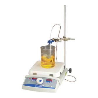
Isotemp Digital Hotplates,
LT1898X1 • 12/28/09
Stirrers and
Stirring Hotplates
OPERATION MANUAL
AND PARTS LIST
Catalog #
1130049HP
1130049S
1130049SHP
Stirring Hotplate
1130149HP
1130149S
1130149SHP
Stirring Hotplate
1130249HP
1130249S
1130249SHP
Stirring Hotplate
1140049HP
1140049SHP
Stirring Hotplate
Type
Top Plate Size and Material
Hotplate
7x7 Ceramic
Stirrer
7x7 Ceramic
7x7 Ceramic
Hotplate
7x7 Ceramic
Stirrer
7x7 Ceramic
7x7 Ceramic
Hotplate
7x7 Ceramic
Stirrer
7x7 Ceramic
7x7 Ceramic
Hotplate
7x7 Aluminum
7x7 Aluminum
Voltage
120
120
120
100
100
100
230
230
230
120
120
Advertisement
Table of Contents

Related Manuals for Fisher Scientific 1130049HP


Summary of Contents for Fisher Scientific 1130049HP
- Page 1 Isotemp Digital Hotplates, Stirrers and Stirring Hotplates OPERATION MANUAL AND PARTS LIST Catalog # Type Top Plate Size and Material Voltage 1130049HP Hotplate 7x7 Ceramic 1130049S Stirrer 7x7 Ceramic 1130049SHP Stirring Hotplate 7x7 Ceramic 1130149HP Hotplate 7x7 Ceramic 1130149S Stirrer...
-
Page 2: Table Of Contents
Table of Contents Safety Information ..............................3 Alert Boxes ..............................3 Warnings ..............................3 General Specifications ............................5 Overall Dimensions ............................5 Top Plate Dimensions ..........................5 Weight ................................5 Heating Specifications ..........................6 Stirring Speed Specifications........................6 Environmental Conditions ..........................7 Declaration of Conformity ..........................7 Unpacking and Installation ..........................8 General Usage..............................8 Unpacking ..............................8 Installation ..............................8... -
Page 3: Safety Information
Safety Information Your Fisher Isotemp Hotplate, Stirrer or Stirring Hot Plate Alert Signals has been designed with function, reliability, and safety in mind. It is your responsibility to install it in conformance with local electrical codes. For safe operation, please pay Warning attention to the alert signals throughout the manual. - Page 4 AFETY NFORMATION hotplates are not explosion proof. Fire or explo- sion may result. Unit contains components which may ignite such materials. Keep top surface clean. Use a non-abrasive cleaner. Alkali spills, hydrofluoric acid spills or phosphoric acid spills may damage top and lead to thermal failure.
-
Page 5: General Specifications
General Specifications Overall Dimensions - W x H x D All Models: 8.2 x 8.2 x 8.2” (20.8 x 20.8 x 20.8 cm) Top Plate Dimensions - W x H x D All Models: 7.25 x 7.25 x 7.25” (18.4 x 18.4 x 18.4 cm) Weight All Models: 11 lbs. -
Page 6: Heating Specifications
ENERAL PECIFICATIONS Heating Specifications Top Plate Surface - Solid Ceramic Temperature range All 4" x 4" and 7" x 7" models: 41°F to 1004°F (5°C* - 540°C) All 10" x 10" models: 41°F to 752°F (5°C - 400°C) Heat-up time to maximum temperature (unloaded top plate). 8 minutes Temperature stability at the center of the top plate surface (@ 100°C). -
Page 7: Environmental Conditions
(Stirrers and Stirring Hotplates) per the provisions of the Electromagnetic Compatibility Directive 2004/108/EC, and per the provisions of the Low Voltage Directive 2006/95/EC. The authorized representative located within the European Community is: Thermo Fisher Scientific Electrothermal House Unit 12A Purdeys Industrial Estate... -
Page 8: Unpacking And Installation
If the unit appears to pheres. have sustained shipping damage contact Fisher Scientific Customer Service at 866-984-3766. The following items are included in the shipment: Isotemp Hotplate, Stirrer or Stirring Hotplate... -
Page 9: Operation
Operation Powering the Unit Warning Set the unit on a flat stable surface at least 12" away from Use caution when heating volatile combustible materials, and plug the cordset into a properly materials; top surface and element grounded electrical outlet of correct voltage and current han- can reach the “Flash Point dling capacity. -
Page 10: Controlling Solution Temperature With An External Probe
PERATION The “CAUTION - HOT TOP” indicator illuminates when the plate reaches 50°C. When the heating is turned off, the indi- cator will continue to flash until the plate temperature drops below 50°C. Controlling Solution Temperature Using External Probe Plug the included probe or an ungrounded Type K thermocou- ple probe into the probe receptacle located on the right side of the unit. -
Page 11: Service And Calibration
Service and Calibration Service Menu The Service Menu has many features that will allow a user to customize their unit. A table of the features available in the Service Menu is given below. The features are given in order of their appearance in the Service Menu when rotating the center knob in a clockwise rotation. -
Page 12: Oil Bath Method Of Calibration
ERVICE AND ALIBRATION Oil Bath Method of Calibration This method of calibration requires a calibrated water or oil bath with digital readout. With the probe connected to the unit, insert the probe connected to the unit to be calibrated into a bath that has stabilized at the desired calibra- tion temperature. -
Page 13: System Method Of Calibration
ERVICE AND ALIBRATION System Method of Calibration - Recommended This method of calibration requires an NIST calibrated thermometer with a resolution of 0.1°C or better. Select an independent temperature probe to be placed in the load, along with the unit temperature probe before continuing with calibration. -
Page 14: Timer Shutdown - End
ERVICE AND ALIBRATION If the unit undergoing calibration does not have stirring capability then skip to the next step. The “Stir” key under the STIR display will be lit, and the displays will show the stirring control set point. The speed may be adjusted by using the center knob. -
Page 15: Probe Temperature Limit - Pl
ERVICE AND ALIBRATION To modify/view the Timer Shutdown follow the instructions given below: Plug the unit into the appropriate power, but do not turn it ON (displays should be blank, unless Hot Top Warning System is indicating a hot sur- face), enter the Service Menu by pressing and holding the POWER key. -
Page 16: Probe Response - Pr
ERVICE AND ALIBRATION a single beep will be heard and you may remove your finger from the POWER key. The display will change to OSP. Rotate the center knob until the display reads PL. Press the “Heat” key under the HEAT dis- play to accept, and the display will change to 250 (250°C limit), or UL (unlimited). -
Page 17: Error Disable - Err
ERVICE AND ALIBRATION The unit will return to the previous menu. Select another feature to change, or press the POWER key again to return to the off mode. Error Disable - Err The purpose of this feature is to enable or disable a par- ticular error from being detected and displayed. -
Page 18: Factory Defaults - Def
ERVICE AND ALIBRATION Factory Defaults - deF This feature is available for all units and is designed to restore the control to the default factory settings. To reset to the Factory Defaults follow the instructions given below: Plug the unit into the appropriate power, but do not turn it on (displays should be blank, unless Hot Top Warning System is indicating a hot sur- face), enter the Service Menu by pressing and... -
Page 19: Troubleshooting
Troubleshooting Error Codes Errors E01 through E07 are heating errors. Error Handler will lock out heating functions if heating error is detected. Stirring functionality is unaffected. If the condition that caused the error is no longer present, pressing the POWER button or unplugging the unit will clear Errors E01-E07. y t i . - Page 20 ROUBLESHOOTING Errors E11 and E12 are stirring errors. Error Handler will lock out stirring functions if stirring error is detected. To avoid boil over, the unit will cease heating (the user can restart heating if desired). Pressing the POWER button or unplugging the unit will clear Error E12. Unplugging the unit will clear Error E11. y t i .
-
Page 21: Replacement Parts List
This assembly includes the ceramic top, element, thermocouple, insulation, baffle plate, and 2 ceramic top holders. Fisher Scientific recommends not replacing individual compo- nents of the top plate. (SHP = Stirring Hotplate, HP = Hotplate, S = Stirrer) 7x7 Ceramic Top Part No. -
Page 22: Accessories
Accessories Part No. Description 05-764Q 90° Clamp Holder 1000-2 12” Aluminum Rod 05-769Q Large Clamp 05-769-5Q Small Clamp (up to 1/2”) 05-809Q Thermometer Clamp 10-666-10GQ Support Rod - 12” 14-666-10BQ Support Rod - 18” 14-666-10CQ Support Rod - 24”... -
Page 24: Warranty
Warranty Laboratory instruments and equipment manufactured by Fisher Scientific Company L.L.C. – Laboratory Equipment Division (hereinafter called “the Company”) are warranted only as stated below. Subject to the exceptions and upon the conditions specified below, the Company agrees, at its election, to...
Need help?
Do you have a question about the 1130049HP and is the answer not in the manual?
Questions and answers