Table of Contents
Advertisement
Quick Links
Advertisement
Table of Contents

Subscribe to Our Youtube Channel
Related Manuals for MAXDATA PLATINUM 9000-4R


Summary of Contents for MAXDATA PLATINUM 9000-4R
- Page 1 MAXDATA PLATINUM 9000-4R Server System OM12884 Product Guide...
-
Page 3: Table Of Contents
External SCSI Connector (Optional) ....................36 Add-In Board Slots .......................... 37 Video ..............................37 SCSI Controller ............................. 37 ICH4 IDE Controller..........................37 Server Management ..........................38 Baseboard Management Controller (BMC)..................38 QLogic GEM359 SCSI Hot-swap Controller ..................39 MAXDATA PLATINUM 90004R Server System... - Page 4 3 Configuration Software and Utilities Power-on Sequence and Power-on Self-Test (POST) ................41 The Extensible Firmware Interface (EFI) Boot Manager ...............41 The Extensible Firmware Interface (EFI) Shell ..................44 Using BIOS Setup ..........................46 Starting Setup ..........................46 Record Your Setup Settings ......................46 Navigating Setup Utility Screens......................47 Primary Screens ..........................47 Advanced..............................
- Page 5 PEF Configuration Initial View ......................90 Enable PEF ............................91 Enable SEL Event Messages for PEF Actions .................91 PEF Startup Delay ..........................91 Alert Startup Delay...........................91 PEF Action Global Settings ......................91 Power Cycle .............................91 Reset ..............................91 Power Down ............................91 MAXDATA PLATINUM 90004R Server System...
- Page 6 Diagnostic Interrupt..........................91 Alert..............................91 Event Filter Settings View ....................... 92 Edit Event Filter View ........................93 Enable Event Filter .......................... 93 Enable Alerts ..........................93 Policy Number Associated With This Event Filter................93 Chassis Action Associated With This Event Filter................93 Configure Policies Button........................
- Page 7 Interface to Server Management ....................118 Sample Setup for Console Redirection ..................119 Server Configuration ........................119 Console Configuration........................119 Terminal Mode Overview........................120 Setup and Configuration.........................120 Connection Mechanism .........................120 Hardware Setup ..........................120 Configuration Using System Maintenance Utility (SMU) ...............120 MAXDATA PLATINUM 90004R Server System...
- Page 8 Serial Channel Configuration ......................120 Direct Connection Mode ........................120 Modem Connection Mode......................121 Sample Setup for Terminal Mode ....................121 Server Configuration: ........................121 Console Configuration:........................122 Logging Into the Terminal Mode Session ..................122 User Configuration .........................122 Username and Password Restrictions ...................122 Terminal Mode Configuration......................122 Line Editing.............................123 Echo ...............................123 Handshaking...........................123...
- Page 9 Figures MAXDATA PLATINUM 9000-4R Server Front View ..............15 Chassis Front View.........................17 Front Panel Controls and Indicators ....................18 Peripheral Bay ..........................19 Hard Disk Drive Carrier........................20 DVD/CD-ROM and LS-240 Drive Carriers ..................21 Location of Processor/Memory Subsystem Serviceability Indicators .......... 22 Chassis Back Features ........................23 Back Panel View Showing Indicator and Switch Locations............24...
- Page 10 56. Save Operation Successful View ....................107 57. SMU Invalid Data Entry Error Example ..................107 58. Remote SMU Help Window (Browser-based) ................108 59. SMU Local Help Window......................110 60. Opening the Back Top Cover .......................136 61. System Fan Location and Removal ....................137 62.
-
Page 11: Part I: User's Guide
Overcurrent protection: The server is designed for an AC line voltage source with up to 20 amperes of overcurrent protection. If the power system for the equipment rack is installed on a branch circuit with more than 20 amperes of protection, you must provide supplemental protection for the server. MAXDATA PLATINUM 90004R Server System... - Page 12 WARNING – POWER CORD RATING Do not attempt to modify or use an AC power cord that is not the exact type required. You must use a power cord that meets the following criteria: • Rating: For U.S./Canada cords must be UL Listed/CSA Certified, 16/3, 75C type, VW-1, SJT/SVT, with NEMA 5-15P or NEMA 6-15P attachment plug and IEC 320 C13 input power connector rated 15 amps.
-
Page 13: Regulatory Specifications And Disclaimers
Europe (CE Declaration of Conformity) This product has been tested in accordance too, and complies with the Low Voltage Directive (73/23/ EEC) and EMC Directive (89/336/EEC). The product has been marked with the CE Mark to illustrate its compliance. MAXDATA PLATINUM 90004R Server System... -
Page 15: System Description Introduction
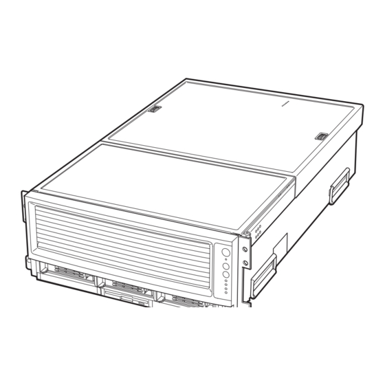
1 System Description Introduction The MAXDATA PLATINUM 9000-4R as shown in Figure 1 is a compact, high-density rack-mount server system with support for one to four Intel Itanium 2 processors and 32-GB DDR SDRAM ® ® memory. The system is based on the Intel S870BN4 board set and the Intel E8870 chipset. -
Page 16: Chassis Description
Chassis Description The chassis provides a modularized processor/memory subsystem, I/O subsystem, and peripheral bay. Other features are outlined in Table 2. Table 2. Chassis Feature Summary Feature Comment Server • Stand-alone system including external I/O PCI slots and disk expansion as needs Configuration grow •... -
Page 17: External Chassis Features
The front panel is located to the right of the processor/memory subsystem and provides user interface for system management via switches and status indicatosr LEDs. The front panel also contains the speaker. Figure 3 shows the control buttons and status indicators on the front panel. Table 3 describes their features. MAXDATA PLATINUM 90004R Server System... -
Page 18: Front Panel Controls And Indicators
OM12886 Figure 3. Front Panel Controls and Indicators Table 3. Front Panel Control and Indicator Description Item Feature Description Switches System ID Switch Toggle switch for blue System ID LEDs (the front panel system ID LED is located inside the system ID switch). See E below for description of LED operation. -
Page 19: Peripheral Bay
The removable media drive bay (lower section) supporting: – One 1⁄2-inch IDE DVD/CD-ROM (B in Figure 4) – One 1⁄2-inch IDE LS-240 drive (C in Figure 4) or removable EMI Filler Panel (D in Figure 4). OM12905 Figure 4. Peripheral Bay MAXDATA PLATINUM 90004R Server System... -
Page 20: Hot-Swap Hard Disk Drive Bay
Hot-swap Hard Disk Drive Bay The hot-swap hard disk drive carrier (see Figure 5) is designed to accept 15,000-RPM (and slower) Ultra320 SCSI technology SCA-type hard disk drives. The peripheral bay is designed to support Low Voltage Differential (LVD) SCSI disk drives only. Single- Ended (SE) SCSI devices are not supported in the peripheral bay. -
Page 21: Removable Media Drive Bays
Examples of such messages include: activate a drive fault indicator; power down a drive that has failed; and report SCSI backplane temperature. • SAF-TE intelligent agent, which acts as proxy for “dumb” I2C devices (that have no bus mastering capability) during intrachassis communications. MAXDATA PLATINUM 90004R Server System... -
Page 22: Processor/Memory Subsystem Serviceability Status Indicators
Two additional LEDs (Green and Amber) and a switch appear on the left side of the processor board. These components are not implemented in the MAXDATA PLATINUM 9000-4R Server system and are not visible or accessible through the front bezel. -
Page 23: Chassis Back
Notes: 1. PCI slots support 3.3 V signal adapter cards only. 2. External SCSI bus supports both LVDS and SE signals via the external SCSI connector. 3. Emergency Management Port (EMP) access is provided via shared serial port. MAXDATA PLATINUM 90004R Server System... -
Page 24: Back Panel
Back Panel Figure 9 shows the location of the indicators and controls found on the back panel. OM12889 Figure 9. Back Panel View Showing Indicator and Switch Locations System ID Indicator LED A. System ID LED (blue) Identifies the system. The system ID LED is activated either by the System ID switch on the front panel or through server management. -
Page 25: Power Supply Led Indicators
Power supply DC outputs ON and Current limit Blinking Predictive failure Blinking/Latched NOTE Proper system cooling requires that the power supply bay be filled either by two power supply modules, or a power supply module and a filler panel. MAXDATA PLATINUM 90004R Server System... -
Page 26: Chassis Top
Chassis Top I/O Subsystem Serviceability Indicators Figure 11 shows the I/O subsystem serviceability indicators. The indicators are located on the I/O board and are visible through the system top cover via light pipes. The I/O serviceability indicators provide system power, system reset, and interlock status for various subsystem and module connectors. These LEDs are powered by standby voltage to provide status as long as AC power is supplied to the system. -
Page 27: Internal Chassis Features
In an N+1 configuration the 48 VDC outputs have active (forced) current sharing and 12 VDCSB outputs have passive current sharing. The two externally enabled outputs have the following ratings: • +48 VDC at: 24.0 A @HI line /13.5 A @LO line • +12 VDCSB at: 4 A @any line MAXDATA PLATINUM 90004R Server System... -
Page 28: Redundant Ac Power Source Operation
Redundant AC Power Source Operation Each power supply module requires one power cord to supply AC power to the system. When two power supply modules and two power cords are installed, the system supports (1+1) power cord redundancy at 220 VAC. This feature allows the system to be powered by two separate AC sources. In this configuration, the system continues to operate without interruption if one of the AC sources fails. - Page 29 A system fan failure is indicated by two LEDs, the LED on the corresponding fan (A in Figure 12), and the Cooling Fault LED on the front panel (B in Figure 12). OM12937 Figure 12. Fan Status Indicators MAXDATA PLATINUM 90004R Server System...
-
Page 31: Board Set Description
2 Board Set Description Figure 13 displays a block diagram of the system and the board set within the system. Figure 13. Server System Block Diagram MAXDATA PLATINUM 90004R Server System... -
Page 32: System Board Set
System Board Set This section highlights the main features of the board set. The board set contains the following: • Processor board • Two memory boards • I/O board • I/O riser card • Midplane board In addition, the server contains the following system boards: •... -
Page 33: Processor Board
NOTE The processor board also contains a switch and two LEDs on the front left corner of the primary side of the board that are not used in the MAXDATA PLATINUM 9000-4R Server system. MAXDATA PLATINUM 90004R Server System... -
Page 34: Processor Overview
Processor Overview Each Intel Itanium 2 processor plugs into a 700-pin Zero Insertion Force (ZIF) socket. Each processor ® ® is powered by a 48 V power pod located adjacent to the processor on the processor board. Attached to the top of each processor is a heat sink that dissipates thermal energy. Memory Boards The processor board is designed to support two memory boards (both of which must be installed for the system to operate). -
Page 35: I/O Board
Integrated Rage XL video controller and memory – Video port – Power control - Advanced Configuration and Power Interface (ACPI) • Speaker control • Integrated standby voltage DC-to-DC converters generating 3.3 V standby and 5 V standby MAXDATA PLATINUM 90004R Server System... -
Page 36: Midplane Board
Midplane Board The passive midplane board contains the following features: • VHDM connectors for the processor/memory subsystem and the I/O subsystem • An HDM connector that routes the SCSI bus, two IDE busses, and miscellaneous signals between the I/O board and the SCSI backplane •... -
Page 37: Add-In Board Slots
The device controls the following: • PIO and IDE DMA/bus master operations • Mode 4 timing • Transfer rates up to 22 MB/sec (33 MB/sec using ultra DMA transfers) • Buffering for PCI/IDE burst transfers • Master/slave IDE mode MAXDATA PLATINUM 90004R Server System... -
Page 38: Server Management
Server Management The server management features are implemented using two micro controllers: the Baseboard Management Controller (BMC) on the I/O board and the QLogic GEM359 SCSI hot-swap controller on the SCSI backplane board. The ICMB controller is integrated in the BMC and provides an interface to the external ICMB via the ICMB board. -
Page 39: Qlogic Gem359 Scsi Hot-Swap Controller
Retrieves hard disk drive fault status, SCSI backplane temperature, and fan failure information via IPMB • Queries the status of the power distribution board by retrieving information from the BMC via IPMB • Controls hard disk drive power-on and power-down, facilitating hot-swapping MAXDATA PLATINUM 90004R Server System... -
Page 41: Configuration Software And Utilities
Boot Maintenance Menu. For information on the EFI Shell, refer to “The Extensible Firmware Interface (EFI) Shell” . Follow these steps to power up the MAXDATA PLATINUM 9000-4R Server: 1. Press the power button on the front control panel. Pressing this button causes the server fans to start up and POST to begin running. -
Page 42: Boot Maintenance Menu Options
Table 7. Boot Maintenance Menu Options Option Description Boot from a File Automatically adds EFI applications as boot options or allows you to boot from a specific file. When you choose this option, the system searches for an EFI directory in all EFI System Partitions in the system. - Page 43 • At the menu, select Set Auto Boot Timeout with the arrow key. • Hit <Enter>. • The system resets. Exit Returns control to the EFI Boot Manager main menu. Selecting this option displays the active boot devices, including a possible integrated shell. MAXDATA PLATINUM 90004R Server System...
-
Page 44: The Extensible Firmware Interface (Efi) Shell
The Extensible Firmware Interface (EFI) Shell The EFI Shell is an EFI application that allows other EFI applications to be launched, EFI device drivers to be loaded, and operating systems to be booted. The combination of the EFI firmware and the EFI Shell provides an environment that can be modified to easily adapt to many different hardware configurations. - Page 45 Move one or more files/directories to destination pause Prompts to quit or continue (scripts only) pci [bus_dev] [func] Displays PCI device information rconnect DeviceHandle# Reconnects one or more drivers from a device [DriverHandle# [ChildHandle#]] | [-r] continued MAXDATA PLATINUM 90004R Server System...
-
Page 46: Using Bios Setup
Table 8. EFI Shell Commands (continued) Command Description reset [reset_string] Performs a cold reset rm file/dir [file/dir] Removes files or directories setsize file Sets size of a new file stall microseconds Delays for the specified number of microseconds time [hh:mm:ss] Gets or sets the time type [-a] [-u] [-b] file Displays the contents of a file... -
Page 47: Navigating Setup Utility Screens
Service Partition options. Also displays BMC and HSC firmware revisions. For details on this screen, see “System Management” . Exit Exits the utility with or without saving utilities and allows management of custom settings. For details on this screen, see “Exit” . MAXDATA PLATINUM 90004R Server System... -
Page 48: Processor Settings Submenu Items
Main Table 10 describes the menu items available on the Main screen. Default values appear in brackets. Table 10. BIOS Setup Main Screen Menu Items Menu Item Default Value Description Language [English (US)] Selects which language BIOS displays. Spanish Italian French German System Time... -
Page 49: Advanced
Clear All [No] Setting to Yes will clear the System Event Log.. Logs POST Error [Enabled] Select “Disabled” if you want the system to boot Pause Disabled with no user intervention on critical POST errors. MAXDATA PLATINUM 90004R Server System... -
Page 50: Security
Security Table 13 describes the menu items available on the Security screen. NOTE With the removal of legacy keyboard and mouse support, the legacy security core has been removed. Therefore, the security menu is briefer than on other server products. Also, the two-level password has been replaced with a single-level password. -
Page 51: System Management
The currently loaded version of Baseboard Management Controller firmware. You cannot change this value. It appears for informational purposes only. HSC Revision [HSC_Rev] Information field only, hidden if not detected. Displays the Hot Swap Controller revision. MAXDATA PLATINUM 90004R Server System... - Page 52 Table 15. Setup Console Redirection Sub Menu Items Sub Menu Item Default Value Description Serial Console Enabled/Disabled When enabled, Console Redirection uses only Redirection COM2. Choosing “Disabled” completely disables Console Redirection. Baud Rate 9600 When Console Redirection is enabled, use the baud [19.2K] rate specified.
-
Page 53: Exit
Lets you discard the changed values you have accumulated during this setup session. Clicking on the menu item causes the system to prompt you for a Yes or No response. Discards the setup values for the current setup utility session. Aborts the action. MAXDATA PLATINUM 90004R Server System... -
Page 54: Lsi Scsi Utility
LSI SCSI Utility The LSI SCSI utility allows you to configure the SCSI capabilities of the server. This configuration utility can be accessed using an EFI-based utility provided by Intel . This utility is available on the ® Resource CD . The EFI utility can be evoked from the EFI shell prompt with the command EFICnfg.efi. -
Page 55: Lsi Scsi Utility Main Menu
Figure 14. LSI SCSI Utility Main Menu To select the adapter you wish to configure, use the arrow keys to highlight the adapter then press <Enter>. The screen clears and a message reading “Scanning for devices…” appears. MAXDATA PLATINUM 90004R Server System... -
Page 56: Adapter Properties
Figure 15 shows the adapter properties and its different configuration settings. LSI Logic MPT SCSI Setup Utility Version v1.00.04.00 Adapter Properties Adapter 53C1030 06 <Device Properties> <Mirroring Properties> <Synchronize Whole Mirror> Driver Support [Enabled BIOS & OS] Host SCSI ID Spinup Delay (Secs) Secondary Cluster Server [No]... -
Page 57: Device Properties
Restore Defaults function does not take you another menu and does not give you the option to cancel. If you make changes and then accidentally select the Restore Defaults function, all changes will be discarded. MAXDATA PLATINUM 90004R Server System... -
Page 58: Device Properties Format Option
LSI Logic MPT SCSI Setup Utility Version v1.00.04.00 Format LSI Logic MPT SCSI Setup Utility Version v1.00.04.00 SCSI Device Identifier Format Maxtor SCSI Device Identifier Status Maxtor WARNING! Format will change the sector size to 512bytes. Format will Permanently erase all data on this device. Format may take hours to complete and cannot be stopped. - Page 59 The above menu shows the exit menu that appears if no changes have been made to the Setup Utility. After exiting, you are returned to the EFI Shell prompt. After exiting, you are returned to the EFI Shell prompt. MAXDATA PLATINUM 90004R Server System...
-
Page 60: Clearing Cmos
Clearing CMOS WARNING Make sure that the rack is anchored securely so it will not tilt forward when the server chassis is extended. A crush hazard exists should the rack tilt forward which could cause serious injury. You must clear CMOS after you complete the IFlash64 BIOS update. Clearing CMOS involves changing a jumper setting on the I/O riser card, restarting the server with the new jumper setting, restoring the jumper setting to its original position, and restarting the server a final time. -
Page 61: Bios Recovery Mode
Remove the LS-240 recovery diskette, switch system power off, and disconnect AC power. Replace the I/O toggle switch #1 to the OFF position, reconnect AC power and switch the system on per updated BIOS release notes (i.e., clear CMOS first-time booting). MAXDATA PLATINUM 90004R Server System... -
Page 62: Using The Sel Viewer Utility
System Event Log of 65,536 bytes (64 KB), and can hold up to 3,276 records. NOTE You can also run this utility directly from the Resource CD. For information, see “The MAXDATA PLATINUM 9000-4R Server Resource CD” . Using the SELViewer Utility, you can do the following: •... -
Page 63: Splash Screen
The SEL Viewer can display event logs in raw hexadecimal format as read from the server. Figure 24 shows SEL records displayed in hexadecimal format. Table 17 explains the abbreviations used in the hexadecimal mode display. MAXDATA PLATINUM 90004R Server System... - Page 64 Table 17. Abbreviations Used in Hex Mode Display Record ID Record Type Time Stamp Generator ID Event Message Format Revision Sensor Type Sensor Number EDIR Event Dir and Event Type Event Data 1 Event Data 2 Event Data 3 Manufacturers ID (used when displaying OEM SEL records type C0h-DFh) OEM defined (used when displaying OEM SEL records type C0h-DFh and E0h-FFh) The SEL Viewer main window contains a display window that displays all the SEL records.
-
Page 65: Status Box
Figure 21. SEL Viewer Utility Main Window Figure 22. Status Box Figure 23. Message for Empty Event Log MAXDATA PLATINUM 90004R Server System... -
Page 66: Pull-Down Menu - File
Figure 24. SEL Records Displayed in Hex Format Pull-Down Menu – File The File pull-down menu includes options for opening and saving system event records from, and to data files, respectively. These options are further described in the sections below. File Menu Item –... -
Page 67: File Menu Item - Save As
The SEL pull-down menu includes options for reloading SEL entries from the server, clearing the SEL entries, viewing SEL properties, and sorting the entries by different column fields. These options are further described in the sections below. MAXDATA PLATINUM 90004R Server System... -
Page 68: Sel Menu Item - Reload
SEL Menu Item – Reload This option allows you to reload the SEL entries from the server. This operation is similar to the one performed when the SEL Viewer is first invoked. The records are displayed either in the hex format or in the interpreted format, depending on the set display mode. -
Page 69: Sel Menu Item - Sort By
To move between windows, use <F10> or <Tab> keys. To dismiss the help window, press <Esc> key. Help Menu Item – About This option displays utility version and copyright information about this utility. It also displays the IPMI driver version that is currently loaded. Figure 28. Help Window MAXDATA PLATINUM 90004R Server System... -
Page 70: Command Line Interface
Command Line Interface This utility parses the command line arguments and sets internal flags to control operation. Any invalid parameters will result in a “usage” message being displayed and the program exiting with an error code (see Appendix D). The command line options are listed in Table 18 and are accessed with the forward slash “/” character. The basic command line format is: Selview [Options] Table 18. -
Page 71: Remote Smu Keyboard Support
For edit box controls, the <LEFT arrow> and <RIGHT arrow> keys can be used to move the cursor within the edit box. To move to a different control, the <Tab>, <Enter>, <UP arrow>, or <DOWN arrow> key must be used. MAXDATA PLATINUM 90004R Server System... -
Page 72: About Box Information
About Box Information The local and remote SMU containers both contain an “About” item in the task pane when the task list is displayed. When About is clicked, a dialog box is displayed showing information about the SMU application version. The information displayed consists of a set of four numbers, defined as follows: a major feature release number;... -
Page 73: Smu Application Startup And Shutdown
The SMU is contained in the set of tools listed under the heading Reboot to Service Partition. Figure 31 below shows the ISM Console with the supported tools shown for a server. Figure 31. ISM Console MAXDATA PLATINUM 90004R Server System... -
Page 74: Connections Between Smu Applications And Core Components
Connections Between SMU Applications and Core Components Remote The path used to connect to a target server is defined by the ISM software based on information it has about each server. Currently, the only supported connection path is LAN. After a connection is established between the remote SMU application and SMU core components running on a server over some physical medium, the application and the core components set up a socket connection to communicate over that medium. -
Page 75: Service Partition Utilities
ISM software, not the SMU, so the appropriate ISM document should be referenced with regard to the types of errors that can occur and the actions taken if such errors take place. Figure 33. Service Partition Utilities MAXDATA PLATINUM 90004R Server System... - Page 76 The remote SMU application then uses Service Partition Utilities services to execute the server-side SMU core components. The remote SMU application attempts to establish a socket connection to the server on an agreed upon socket. The application waits for a predefined amount of time (up to several seconds) before indicating to you that it failed to establish a connection.
-
Page 77: Startup Of The Local Smu Application
2. Use the arrow keys to navigate to the “Utilities” menu item. Press the <Enter> key. 3. Use the down arrow key to highlight the System Maintenance Utility menu item. Press the <Enter> key. This causes the local SMU application (smu.efi) to be started. MAXDATA PLATINUM 90004R Server System... -
Page 78: Running From The System Partition
Running from the System Partition If the SMU has been installed on a system partition, it can be run from there. To do this, follow the steps below: 1. If an EFI shell prompt is available on the local console and the files on the system partition can be accessed, skip to step 3. -
Page 79: Lan Channel Configuration Subtask
The LAN channel configuration subtask allows a user to modify settings related to the LAN channel. LAN Channel Configuration Initial View The initial view for configuring the LAN channel is shown in Figure 37 . The configuration settings are described below. Figure 37. LAN Channel Configuration MAXDATA PLATINUM 90004R Server System... -
Page 80: Access Mode
Access Mode This option is used to configure the access mode for the LAN channel. The available options are described below. Always Available The channel is dedicated to communication with the BMC and is available during all system states (powered-down, powered-up, pre-boot, sleep, run-time, etc.). Disabled The channel is disabled from being used to communicate with the BMC. -
Page 81: Subnet Mask
MAC address, you will be informed of this and asked to provide the MAC address in the edit box provided in this view. The view is redisplayed with this checkbox unchecked. Any user data previously entered remains in the view. MAXDATA PLATINUM 90004R Server System... -
Page 82: Default Lan Configuration Settings Set By The Smu
This checkbox is checked by default unless the MAC address edit box appears to have a valid MAC address. A MAC address of 00-00-00-00-00-00 is considered invalid, so the checkbox would get checked when the SMU displays the view in that case. If the checkbox is unchecked, the default gateway MAC address edit box becomes active (it is grayed out when this checkbox is checked). -
Page 83: Enable Lan Alerting
The number of times the alert will be retried. • The interval in seconds between retries. The number of LAN alert destinations is platform specific. For the MAXDATA PLATINUM 9000-4R Server, the number of LAN alert destinations is 4. MAXDATA PLATINUM 90004R Server System... -
Page 84: New, Edit, And Delete Buttons
New, Edit, and Delete Buttons If the New button is clicked, a view is displayed to allow configuring of a new LAN destination address; refer to the following section. If the Edit button is clicked, a view is displayed to allow editing of the configuration for the currently selected destination IP address (the address whose radio button is selected in the list). -
Page 85: Destination Mac Address
IP address. If this checkbox is not checked, the backup gateway IP address is used as the gateway IP address. If no backup gateway was specified when the LAN channel configuration was done, this checkbox will not be displayed. MAXDATA PLATINUM 90004R Server System... -
Page 86: Serial Over Lan Configuration View
Serial Over LAN Configuration View The serial over LAN view shown in Figure 40 allows configuring the operation of the serial over LAN capability of the BMC. Figure 40. Serial Over LAN Configuration View Enable Serial Over LAN This checkbox is used to enable or disable the serial over LAN capability. SOL Privilege Level This setting is used to select the minimum operating privilege level that is required to be able to activate SOL. -
Page 87: User Configuration Subtask
This number is platform-specific and is obtained by the SMU from the firmware. For the MAXDATA PLATINUM 9000-4R Server platform, the number of users allowed is 4. This view shows whether a particular user is enabled or disabled for channel access;... -
Page 88: Edit User View
Edit User View Figure 42 shows the view that is displayed when the Edit button is clicked on the User Configuration main view. Note that any changes made to user settings do not take affect until the next time that user establishes a session. -
Page 89: Enter/Verify New Password
“No Access” option, which disables a user from establishing a session on the channel. This option is available as a user privilege but not as a channel privilege. MAXDATA PLATINUM 90004R Server System... -
Page 90: Platform Event Filtering (Pef) Subtask
Platform Event Filtering (PEF) Subtask The Platform Event Filtering (PEF) subtask provides a mechanism for configuring the BMC to take selected actions on event messages that it receives or has internally generated. These actions include operations such as system power-off and system reset as well as triggering the generation of an alert. -
Page 91: Enable Pef
If checked, this checkbox globally enables the system power down action when an event filter is triggered. Diagnostic Interrupt If checked, this checkbox globally enables a diagnostic (non-maskable) interrupt when an event filter is triggered. Alert If checked, this checkbox globally enables alerts when an event filter is triggered. MAXDATA PLATINUM 90004R Server System... -
Page 92: Event Filter Settings View
Event Filter Settings View The PEF event filters settings view, shown in Figure 44, displays to users the supported pre-configured event filters on the platform to which the SMU is communicating, along with settings associated with the event filters. These associated settings are: •... -
Page 93: Edit Event Filter View
From that view, a user can edit a policy table entry or configure an unused entry. This button is supplied as a way to define the settings associated with a policy number that can be selected from the drop-down list described in the previous section. MAXDATA PLATINUM 90004R Server System... -
Page 94: Ok Button
OK Button Clicking the OK button saves all settings currently shown in this view in the internal copy of the data. The Save button on the last PEF view must be clicked to store these settings into non-volatile storage. You are returned to the Event Filter Settings view after clicking OK. Cancel Button Clicking the Cancel button returns you to the Event Filter Settings view without saving any changes made to the selected event filter in the internal copy of the data. -
Page 95: Edit
Selecting an alert policy table entry and then clicking the Edit button displays a view that allows a user to change the settings for that table entry. The settings that can be changed are described in more detail in 123. MAXDATA PLATINUM 90004R Server System... -
Page 96: Edit Alert Policy Entry View
Edit Alert Policy Entry View The view shown in Figure 47 is displayed after clicking the Edit button in the Alert Policy Table view. The data shown is for whatever entry in the policy table was selected when the Edit button was clicked. -
Page 97: Policy Type
You are returned to the Alert Policy Table view after clicking OK. Cancel Button Clicking the Cancel button returns you to the Alert Policy Table view without saving any changes made to the selected alert policy table entry in the internal copy of the data. MAXDATA PLATINUM 90004R Server System... -
Page 98: Serial/Modem Channel Configuration Subtask
Serial/Modem Channel Configuration Subtask This section describes the views presented to configure serial/modem channel settings. Serial/Modem Channel Configuration Initial View The serial/modem channel configuration subtask allows you to modify settings that relate to the serial/modem channel, set up dial strings to which alerts are sent, and specify the settings related to sending alerts to those destinations. -
Page 99: Pre-Boot Only
Save button on the last serial/modem configuration view. Authentication type enables are enabled. These bits define what types of authentication are enabled to authenticate messages sent to the BMC by users of different privilege levels. The SMU enables MAXDATA PLATINUM 90004R Server System... -
Page 100: Modem Mode Configuration View
authentication of type straight password, MD2, MD5, and none. (Refer to the IPMI specification for more information on these authentication types.) Basic mode is enabled, allowing basic serial communications to take place over the serial/modem channel. Session inactivity timeout is set to one minute. Session termination bits are enabled to enable ending of a serial/modem session if an inactivity timeout occurs or if DCD is lost. -
Page 101: Dial Command
Since the number of dial strings available is platform-dependent, the number available on the target platform is shown above the list of dial strings. For the MAXDATA PLATINUM 9000-4R Server, the number of destination dial strings is 6. The length of a destination dial string is platform-dependent;... -
Page 102: New/Edit Dial String View
The number of destinations is platform-dependent; for the MAXDATA PLATINUM 9000-4R Server, the number of page destinations is 8. Note that all page destinations are shown in this view. -
Page 103: Enable Paging
0-255. Call Retry Interval This setting gives the number of seconds between call retries when a busy signal is detected. The value entered must be in the range 0-255. MAXDATA PLATINUM 90004R Server System... -
Page 104: Edit Page Destination View
Edit Page Destination View The menu shown in Figure 53 allows a user to configure or modify the settings for a page destination. Note that not all settings displayed in the page destination view can be changed; the ones that cannot be changed are not shown in the settings view. -
Page 105: Call Retries
<Backspace><Space><Backspace> sequence when <Backspace> or <Delete> is received. Turn BMC Echo of Received Characters On This setting allows a user to enable the BMC echoing characters it receives when in terminal mode. Checking the checkbox enables this feature. MAXDATA PLATINUM 90004R Server System... -
Page 106: Enable Handshake When Bmc Ready To Receive Another Message
Enable Handshake When BMC Ready To Receive Another Message This setting enables or disables whether the BMC handshakes when ready to receive another message from you. Checking the checkbox enables this feature. Newline Output Sequence This setting allows you to select which characters the BMC uses as a <newline> sequence when the BMC writes a line to the console when in terminal mode. -
Page 107: Save Operation Success/Failure View
These views also have an “OK” button on them. When you click “OK” , the last view displayed is redisplayed. You may also be informed as to whether the error was serious enough that you should shut down the SMU software or reboot the server. MAXDATA PLATINUM 90004R Server System... -
Page 108: Data Corruption Errors That The Smu Application Can Handle
Data Corruption Errors That the SMU Application Can Handle Data corruption errors that the SMU may be able to handle include corruption of template files used by the SMU (files that represent UI views to be sent from the core components to the application). In this type of case, the SMU can detect that there is a problem when it is not able to correctly parse such a file, which means the application is not able to correctly display a view. -
Page 109: Remote Smu Help Use Cases
If a help browser window was previously launched from the Contents task of the SMU application, then when a Help button on an SMU view is clicked, the information pane of that window is replaced with the context-sensitive help for the view containing the Help button. MAXDATA PLATINUM 90004R Server System... -
Page 110: Help For The Local Smu Application
Help for the Local SMU Application Help for the local SMU application appears in a modeless window on the client console since there is no browser available as when running remotely. This means that when you want to return to the local SMU application, it is necessary to click on some part of the application window. -
Page 111: Shutting Down The Server
To shut down the server you must exit the operating system (if applicable) and then use the power button to power down the server. Follow these steps to power down the MAXDATA PLATINUM 9000-4R Server. 1. If the server is running an operating system, use its commands or GUI to logoff (if necessary) and exit the operating system. -
Page 112: Understanding The General User Interface
Understanding the General User Interface The platform diagnostics application uses multiple screens from which you can choose execution options, enable or disable tests for execution, and define test parameters. The initial screen consists of four pull down menus: • File •... -
Page 113: Setting Test Options
All test results are appended to the previous log file. To clear the log file select the Clear log button on the View Results window. Note: because the log file is now always appended, it is recommended that the file be cleared a regular basis to keep the file size from getting too large. MAXDATA PLATINUM 90004R Server System... -
Page 114: Efi Service Partition
EFI Service Partition The EFI Service Partition provides the ability to remotely access an server running EFI, via modem or LAN, for the purpose of executing configuration/setup utilities, remote diagnostics, and any other software designed to be compatible with this environment. Service Partition Requirements 1. -
Page 115: Booting The Server From The Service Partition
Modem reaction to DTR set to return to command state (e.g., AT&D1). Failure to provide item #2 results in the modem either dropping the link when the server reboots (as in AT&D0) or becoming unresponsive to server baud rate changes (as in AT&D2). MAXDATA PLATINUM 90004R Server System... -
Page 116: Keystroke Mappings
The Setup/EMP option for handshaking must be set to CTS/RTS + CD for optimum performance. The CD refers to carrier detect. If EMP is sharing the COM port with serial redirection, the handshaking must be set to CTS/RTS+ CD. In selecting this form of handshaking, the server is prevented from sending video updates to a modem that is not connected to a remote modem. - Page 117 Insert ^[[L Delete (7Fh) Home ^[[H ^[[K Pg Up ^[[M Pg Down ^[[2J Up Arrow ^[[A Down Arrow ^[[B Right Arrow ^[[C Left Arrow ^[[D (09h) NS = Not supported, (xxh) = ASCII character xx MAXDATA PLATINUM 90004R Server System...
-
Page 118: Limitations
Table 22. ASCII Key Mappings Normal Shift Ctrl Backspace (08h) (08h) (7Fh) ^[}(08h) (accent) ` (tilde) ~ ^[}` ^[}1 ^[}2 ^[}3 ^[}4 ^[}5 ^[}6 & ^[}7 ^[}8 ^[}9 ^[}0 (dash) - (under) _ (1Fh) ^[}- ^[}= a to z a to z A to Z (01h) to (1Ah) ^[}a to ^[}z... -
Page 119: Sample Setup For Console Redirection
8. Leave the default settings for the other boxes. Click “OK” to accept the settings and enter the Hyperterminal screen. 9. At this point, power on the server. The console starts displaying the redirection once the video synchronizes on the server. MAXDATA PLATINUM 90004R Server System... -
Page 120: Terminal Mode Overview
Terminal Mode Overview Terminal mode is a feature that allows you to directly interface to the server’s Baseboard Management Controller (BMC) via a serial port connection and execute text-based commands. Two types of text commands are supported: • A limited selection of text commands •... -
Page 121: Modem Connection Mode
26. Click “OK” at the User Save Result menu to return to the Home menu. 27 . At the Home menu, click on the “Exit” option in the Navigation pane to exit SMU, click “OK” to confirm the exit. 28. Reboot the server. MAXDATA PLATINUM 90004R Server System... -
Page 122: Console Configuration
Console Configuration: 1. Boot the console into the OS. 2. Launch Hyperterminal by clicking on the “Start” button in the task bar. 3. Select “Programs>Accessories>Communications” and click on Hyperterminal. 4. At the Connection Description window, enter “guest” for the name and click “OK” to proceed. 5. -
Page 123: Line Editing
Since the terminal mode password is sent via clear text, it is highly desirable that the terminal mode session takes place in a secure location over a secure link, preferably via a direct connection. Connection via a modem is supported but not recommended. MAXDATA PLATINUM 90004R Server System... -
Page 124: Terminal Mode Commands
Terminal Mode Commands Input Restrictions Terminal mode messages are bound by the restrictions listed in the following subsections. Syntax Terminal mode messages follow the general syntax below: [<message data>]<newline sequence> Each terminal mode message must be preceded with the left bracket “start” character and must be ended with a right bracket “stop”... -
Page 125: Text Command Format
LUN. Table 25 lists the supported BMC combinations for IPMI message bridging. Any other combinations are unsupported. Note that IPMI messages to and from the system interface are transferred using the BMC SMS (System Management Software) LUN, 10b, and with the bridge field set to 00b. MAXDATA PLATINUM 90004R Server System... -
Page 126: Terminal Mode Text Commands
Table 25. Supported BMC Combinations for IPMI Message Bridging Bridge Request/ Message Message Field Response Direction (to Interpretation BMC) Request 00b, Remote Console request to BMC functionality 01b, Message is a request from the remote console to the BMC Response 00b, Response to Remote Console from BMC 01b,... - Page 127 XX and YY represent hex-ASCII encoding for data bytes 1 and 2 as specified in the Terminal Mode Configuration Table below. The BMC returns the same output as for SYS SET TCFG, above. SYS RESET Directs the BMC to perform an immediate system hard reset. continued MAXDATA PLATINUM 90004R Server System...
- Page 128 Table 26. Terminal Mode Text Commands (continued) Command Switches Description Directs the BMC to perform an immediate system power off. POWER Causes the BMC to initiate an immediate system power on. POWER ON Causes the BMC to return a high level version of the system health HEALTH status in ‘terse’...
-
Page 129: Boot Option Parameters
[1] - 1b = Do not clear valid bit on pushbutton reset / soft-reset (e.g. “Ctrl-Alt-Del”) [0] - 1b = Do not clear valid bit on power up via power pushbutton or wake event continued MAXDATA PLATINUM 90004R Server System... - Page 130 Table 27. Boot Option Parameters (continued) Parameter Parameter Data (non-volatile unless otherwise noted) Boot info These flags are used to allow individual parties to track whether they’ve acknowledge already seen and handled the boot information. Applications that deal with (semi- boot information should check the boot info and clear their corresponding volatile) bit after consuming the boot options data.
- Page 131 010b = Requests BIOS to force mux to system at conclusion of POST/start of OS-boot. If honored, this overrides the recommended setting of the mux at the end of POST. (See IPMI specification for more info) Data 5 - Reserved continued MAXDATA PLATINUM 90004R Server System...
- Page 132 Table 27. Boot Option Parameters (continued) Parameter Parameter Data (non-volatile unless otherwise noted) Boot initiator Address & Identity information for the party that initiated the boot. info The party that initiates the boot writes this parameter and the boot (semi- info acknowledge parameter prior to issuing the command that causes volatile) the system power up, power cycle, or reset.
-
Page 133: Terminal Mode Configuration
[3:0] - Input newline sequence (Console to BMC). Selects what characters the console uses as the <newline> sequence when writing to the BMC in Terminal Mode 0h = reserved 1h = <CR> (Factory default) 2h = <NULL> All other = reserved MAXDATA PLATINUM 90004R Server System... -
Page 135: Hot-Swapping System Components
1. If the chassis is rack-mounted, slide the chassis out far enough to expose the back top cover (see warning above). 2. Unlatch the back top cover by pressing the latches (A in Figure 60) and sliding the cover (B in Figure 60). MAXDATA PLATINUM 90004R Server System... - Page 136 OM12890 Figure 60. Opening the Back Top Cover 3. Locate the fan you are replacing. If it is a failed fan, the amber LED on the failed fan will be lit. 4. Place your fingers into the fan holes and squeeze your fingers together to release the fan latch and pull the fan out.
-
Page 137: Hot-Swapping Hard Disk Drives
Green, flashing Indicates the hard drive is active Yellow/Green flashing Indicates a hard drive fault status and hard drive is active Yellow/Blank flashing Indicates a hard drive fault status Not illuminated Hard drive is powered MAXDATA PLATINUM 90004R Server System... -
Page 138: Removing A Hard Disk Drive
Removing a Hard Disk Drive 1. Examine the amber LEDs above the Hard Drive Bays to determine which drive has failed. See Table 29 for information on how to interpret the LEDs. 2. Pull the drive carrier latch open and use the handle to pull the drive assembly toward you as shown by the arrows in Figure 62. -
Page 139: Determining Power Supply Status
No AC power to any power supplies No AC power to a specific power supply or power supply failure AC present / Standby output on Blinking DC outputs on and okay Current limit Blinking Predictive failure Blinking MAXDATA PLATINUM 90004R Server System... -
Page 140: Removing A Power Supply
Removing a Power Supply CAUTION Any unused power supply slots must be covered with a filler panel. Uncovered slots can disrupt the airflow used for cooling the system. 1. Locate the power supply you want to remove. 2. Push the thumb latch (A in Figure 64 to unlock the power supply handle and pull the handle (in direction B in Figure 64) to undock the supply. -
Page 141: Installing A Power Supply
7 . As shown by arrow B in Figure 65, rotate the handle to lock the power supply into place. 8. Check the new power supply’s LEDs to verify proper power supply function. OM12962 Figure 65. Installing a Power Supply MAXDATA PLATINUM 90004R Server System... -
Page 142: Hot Plugging Pci Add-In Cards
Hot Plugging PCI Add-in Cards Before replacing a hot-plug PCI I/O card without shutting down the server, use the operating system or a resident GUI to shut down or power off the PCI I/O slot you are working on. Verify that the green power LED for the slot is off before replacing the card. - Page 143 If you are installing a new board, begin with step 5 in Installing Hot-plug PCI Add-in Cards below. 14. Close the chassis top cover. 15. If the system is installed in a rack, push the system back into the cabinet rack. MAXDATA PLATINUM 90004R Server System...
-
Page 144: Installing Hot-Plug Pci Add-In Cards
Installing Hot-plug PCI Add-in Cards 1. Observe the safety precautions, warnings, and cautions described in “Warnings and Cautions” . 2. If your server is operating, use your operating system or GUI application to make sure the PCI slot that you are installing the board into is powered down. 3. - Page 145 BIOS installed on the system to verify whether using the attention button to initiate the slot power up is supported. 15. If the system is installed in an equipment rack, push the system back into place. MAXDATA PLATINUM 90004R Server System...
-
Page 147: Warnings
5 Warnings WARNING: English (USA) AVERTISSEMENTS : Français WARNUNG: Deutsch AVVERTENZA: Italiano ADVERTENCIA: Español MAXDATA PLATINUM 90004R Server System... -
Page 148: Warning: English (Usa)
WARNING: English (USA) The power supply in this product contains no user-serviceable parts. There may be more than one supply in this product. Refer servicing only to qualified personnel. Do not attempt to modify or use the supplied AC power cord if it is not the exact type required. - Page 149 Servers can be too heavy for a single person to lift or move safely. Depending on the server, use two people or a mechanical assist to lift or move the server. MAXDATA PLATINUM 90004R Server System...
-
Page 150: Avertissements : Français
AVERTISSEMENTS : Français Le bloc d‘alimentation de ce produit ne contient aucune pièce pouvant être réparée par l‘utilisateur. Ce produit peut contenir plusieurs blocs d‘alimentation. Veuillez contacter un technicien qualifié en cas de problème. Ne pas essayer d‘utiliser ni de modifier le câble d‘alimentation CA fourni, s‘il ne correspond pas exactement au type requis. - Page 151 Il se peut que les serveurs soient trop lourds pour qu‘une seule personne puisse les soulever et les déplacer en toute sécurité. En fonction du serveur, utilisez deux personnes ou utilisez un équipement mécanique auxiliaire pour soulever ou déplacer le serveur. MAXDATA PLATINUM 90004R Server System...
-
Page 152: Warnung: Deutsch
WARNUNG: Deutsch Das Netzteil dieses Computers enthält keine wartungsbedürftigen Teile. Dieses Produkt kann über mehrere Netzteile verfügen. Überlassen Sie Wartungsarbeiten nur qualifizierten Fachleuten. Versuchen Sie nicht, das mitgelieferte Netzkabel zu verändern oder einzusetzen, wenn es nicht exakt dem benötigten Kabeltyp entspricht. Das Produkt kann über mehrere Netzkabel verfügen. - Page 153 Gerät nur über dieses Kabel vom Netz getrennt wird. Um einen Server sicher anzuheben und zu bewegen ist eine Person nicht ausreichend. Bewegen Sie den Server, je nach Größe, entweder zu zweit oder mittels einer mechanischen Hilfe. MAXDATA PLATINUM 90004R Server System...
-
Page 154: Avvertenza: Italiano
AVVERTENZA: Italiano L ‘alimentatore contenuto nel computer non contiene parti riparabili dall‘utente. Questo prodotto può essere fornito con più alimentatori. Per l‘assistenza fare riferimento solo a personale qualificato. Non tentare di modificare o utilizzare cavi di alimentazione in c.a. che non siano del tipo prescritto. - Page 155 I server possono risultare troppo pesanti per essere sollevati o spostati da una sola persona. Alcuni server devono dunque essere sollevati o spostati da due persone o da un assistente tecnico. MAXDATA PLATINUM 90004R Server System...
-
Page 156: Advertencia: Español
ADVERTENCIA: Español La fuente de alimentación de este producto no contiene piezas que puedan ser reparadas por el usuario. Puede que haya más de una fuente de alimentación en este producto. Para las reparaciones, consulte sólo con el personal cualificado. No intente modifica ni utilizar el cable de alimentación de CA suministrado si no es del tipo exacto requerido. - Page 157 Los servidores pueden ser demasiado pesados para que una sola persona los levante o los mueva de forma segura. Dependiendo del servido, utilice dos personas o una ayuda mecánica para levantar o mover el servidor. MAXDATA PLATINUM 90004R Server System...
-
Page 159: Troubleshooting
LS-240 or • IDE cable or power cable not • Check seating of drive into adapter board. CD ROM not connected to drives. • Check that BIOS setup has these devices enable. recognized by BIOS/EFI MAXDATA PLATINUM 90004R Server System...
Need help?
Do you have a question about the PLATINUM 9000-4R and is the answer not in the manual?
Questions and answers