Table of Contents
Advertisement
Quick Links
Document revision: UM00014EN-AF
Date: 2023-08
24/7 ASSET MONITORING SOLUTION
HTR02 USER MANUAL
SENSeOR (head office)
Bâtiment Natura 2
1198, avenue du Docteur
Maurice Donat
06250 Mougins
France
Contact address:
support.senseor@wika.com
Regional distributors
Visit
www.senseor.com
for
the latest distribution
locations.
Advertisement
Table of Contents

Related Manuals for WIKA SENSeOR HTR02


Summary of Contents for WIKA SENSeOR HTR02
- Page 1 Document revision: UM00014EN-AF Date: 2023-08 24/7 ASSET MONITORING SOLUTION HTR02 USER MANUAL SENSeOR (head office) Bâtiment Natura 2 1198, avenue du Docteur Maurice Donat 06250 Mougins France Contact address: support.senseor@wika.com Regional distributors Visit www.senseor.com the latest distribution locations.
-
Page 2: Warranty
24/7 ASSET MONITORING SOLUTION UM00014EN-AF WARRANTY These products are warranted to be free from functional defects in material and in workmanship at the time of the manufacturing and to conform at that time to the specifications set forth in the relevant instruction manuals or in the data sheets, for such products for a period of one year. -
Page 3: Table Of Contents
24/7 ASSET MONITORING SOLUTION UM00014EN-AF TABLE OF CONTENTS WARRANTY .............................. 2 TABLE OF CONTENTS ..........................3 SAFETY INSTRUCTIONS ..........................5 CONVENTIONS ......................... 5 SAFETY INFORMATIONS ......................6 OVERVIEW ............................... 7 RELATED DOCUMENTS ......................7 AVAILABLE PRODUCTS ......................7 INSTRUCTIONS FOR USE ......................8 READER OVERVIEW ......................... - Page 4 24/7 ASSET MONITORING SOLUTION UM00014EN-AF 1.9.5 NUMBER OF READERS ....................21 1.9.6 MODBUS-RTU DEFAULT CONFIGURATION ..............21 1.9.7 CABLING FOR ETHERNET COMMUNICATION ..............22 1.10 ENVIRONMENTAL SENSOR CONNECTION ................23 SYSTEM INSTALLATION & CONFIGURATION ..................24 1.11 SAW TEMPERATURE SENSORS INSTALLATION ..............24 1.12 SYSTEM CONFIGURATION .....................
-
Page 5: Safety Instructions
24/7 ASSET MONITORING SOLUTION UM00014EN-AF SAFETY INSTRUCTIONS IT IS IMPORTANT TO READ THIS MANUAL BEFORE INSTALLING OR COMMISSIONING SENSEOR ASSETS MONITORING SYSTEM. CONVENTIONS DANGER DANGER INDICATES AN IMMINENTLY HAZARDOUS SITUATION, WHICH, IF NOT AVOIDED, WILL RESULT IN DEATH OR SERIOUS INJURY. FAILURE TO FOLLOW THE INSTRUCTIONS GIVEN WILL RESULT IN DEATH OR SERIOUS INJURY. -
Page 6: Safety Informations
24/7 ASSET MONITORING SOLUTION UM00014EN-AF SAFETY INFORMATIONS ► Protect product from moisture and humidity. ► Protect product from too high or too low temperature. ► Protect product from fire. ► Do not paint the product. ► Do not modify or disassemble the product. Service must be carried out by SENSeOR. ►... -
Page 7: Overview
24/7 ASSET MONITORING SOLUTION UM00014EN-AF OVERVIEW CAUTION THIS READER IS DEDICATED TO SWITCHGEAR MONITORING WITH WIRELESS PASSIVE SAW TEMPERATURE SENSORS, ENVIRONMENTAL SENSOR AND UHF PARTIAL DISCHARGE DETECTION. IT IS DESIGNED FOR USE INSIDE METALLIC CAVITIES ONLY LIKE THE SWITCHGEAR CABINET AND TUNED TO BE COMPLIANT WITH IEC 62271 ENABLING A LICENSE-FREE USE IN SWITCHGEAR WORLDWIDE. -
Page 8: Instructions For Use
24/7 ASSET MONITORING SOLUTION UM00014EN-AF INSTRUCTIONS FOR USE The HTR02 reader is dedicated to monitor electrical equipment like switchgears. The temperature of live conductors is measured by SAW sensors and prevent overheating and overload. Partial discharges are measured by antenna pairs and prevent equipment failure. Ambient temperature and humidity measurements are also available through an optional environmental sensor connected with wires to... -
Page 9: Reader Overview
24/7 ASSET MONITORING SOLUTION UM00014EN-AF READER OVERVIEW Included in scope of delivery: 1x HTR02 reader. 1x µSD card. 1x 4-pin power connector. 1x 4-pin environmental sensor connector (for HTR02-6AWS readers). 1.3.1 SERIALIZATION LABEL Figure 1: HTR02-6AWS-PDD reader serialization label 1.3.2 FRONT LABEL Figure 2: HTR02-2AWS front product label Figure 3: HTR02-6AWS front product label SENSeOR... -
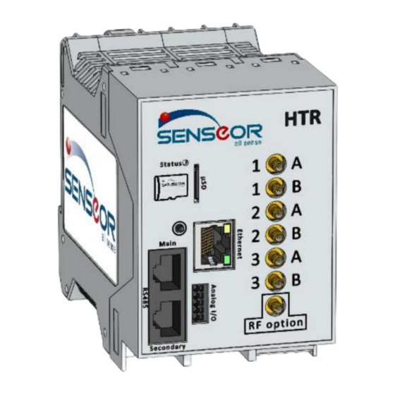
Page 10: Connectors And Functions
24/7 ASSET MONITORING SOLUTION UM00014EN-AF CONNECTORS AND FUNCTIONS Status led µSD card reader Alarm acknowledgement push button Ethernet RJ45 connector RS485 Modbus RJ45 connectors Analog inputs/outputs connector Power input connector Ambient temperature and humidity probe connector RF SMB connectors of antenna pairs (only one antenna pair available for HTR02-2AWS) 1.4.1 INPUT POWER (MAIN CONNECTOR) Type Description... -
Page 11: Rs485 Ports
24/7 ASSET MONITORING SOLUTION UM00014EN-AF 1.4.2 RS485 PORTS RJ45 ports for Modbus-RTU communication. Type Description 1 (left) Not used Not used Not used Data + Data - Not used Not used 8 (right) Ground Figure 4: RS485 socket pinout 1.4.3 ENVIRONMENTAL SENSOR Type Description 1 (left) -
Page 12: Analog Inputs/Outputs (Front Self-Tightening Connector)
24/7 ASSET MONITORING SOLUTION UM00014EN-AF 1.4.4 ANALOG INPUTS/OUTPUTS (FRONT SELF-TIGHTENING CONNECTOR) Type Description 1 (top) TRIG OUT Alarm relay activation output I IN 4–20 mA input SYNC IN Digital input I OUT 4–20 mA output 5 (bottom) V OUT 0–10V output Figure 6: Analog I/Os socket pinout 1.4.5 RF ANTENNAS Connector... -
Page 13: Status Led
24/7 ASSET MONITORING SOLUTION UM00014EN-AF STATUS LED Status LED is used to indicate the functional state of reader. Description LED status No power Installation mode Configuration mode Measure mode (SAW & partial discharge) SAW measurements demonstration mode PDD measurements demonstration mode Warning threshold reached Alert threshold reached System error... -
Page 14: Installation
24/7 ASSET MONITORING SOLUTION UM00014EN-AF INSTALLATION IMPORTANT THE INSTALLATION INSTRUCTIONS ARE ONLY FOR THE HTR02 READER. IT IS ASSUMED THAT SAW TEMPERATURE SENSORS AND PARTIAL DISCHARGE PROBE ANTENNAS HAVE BEEN CONFIGURED AND INSTALLED. WARNING PROFESSIONAL INSTALLATION REQUIRED. INSTALLATION AND CONFIGURATION SHOULD BE PERFORMED ONLY BY USERS WHO ARE TECHNICALLY COMPETENT AND AUTHORIZED TO DO SO. -
Page 15: Unpacking
24/7 ASSET MONITORING SOLUTION UM00014EN-AF UNPACKING 1.6.1 PHYSICAL DIMENSIONS Product Dimensions HTR02-2AWS 45 x 99 x 117 mm HTR02-6AWS(-PDD) 68 x 99 x 117 mm Figure 9: Readers dimensions views SENSeOR HTR02 User Manual 15/30 www.senseor.com... -
Page 16: Din Rail Mounting
24/7 ASSET MONITORING SOLUTION UM00014EN-AF DIN RAIL MOUNTING CAUTION ENSURE THAT THE LOW-LEVEL COMPARTMENT WHERE THE READER IS MOUNTED IS SUFFICIENTLY VENTILATED TO PREVENT OVERHEATING. THE DEVICE MUST BE ELECTRICALLY GROUNDED FOR EMC COMPLIANCE. The reader is designed for installation on a grounded 35 mm DIN rail. DIN rail fixation is integrated on its rear enclosure. -
Page 17: Reader Emplacement
24/7 ASSET MONITORING SOLUTION UM00014EN-AF 1.7.1 READER EMPLACEMENT The reader is intended to be installed in the low voltage compartment of the switchgear. The other electrical assets are recommended to be weather protected in an enclosed location. Figure 11: Reader emplacement in switchgear The reader is required to be installed within a maximum distance of 10 meters from the antennas, corresponding to the maximum length of the antenna coaxial cable for SAW temperature sensors and partial discharge measurement. -
Page 18: Wiring
24/7 ASSET MONITORING SOLUTION UM00014EN-AF WIRING POWER The reader power connector is a 2-pin male connector. This screw connector supports from 16 to 26 AWG wires. For stranded conductor use connector ferrules on the termination. Figure 13: Connector ferrule 1.8.1 INPUT POWER The reader operates at 24VDC nominal with a total power consumption of 6 Watts maximum. -
Page 19: Internal Battery
24/7 ASSET MONITORING SOLUTION UM00014EN-AF 1.8.2 INTERNAL BATTERY SENSeOR reader has an internal 3VDC non rechargeable battery to keep the UTC date and the time in case of power down. Battery needs to be replaced if voltage value is under 2.7V. It can be replaced only by authorized person using the following or an equivalent reference: Figure 15: 3V Lithium CR1632 battery 1.8.2.1... -
Page 20: Communication Connections
24/7 ASSET MONITORING SOLUTION UM00014EN-AF COMMUNICATION CONNECTIONS The components are used to connect Modbus devices, energy communication systems and industrial equipment with each other and to SCADA or cloud systems. The reader could be connected to a network using RS485 Modbus-RTU or Ethernet Modbus-TCP. 1.9.1 CABLING FOR RS485 COMMUNICATION SENSeOR recommends the use of shielded cable for the RS485 wiring, providing at least one twisted pair, one single line, and a drain wire. -
Page 21: Bus Data Rate
24/7 ASSET MONITORING SOLUTION UM00014EN-AF 1.9.3 BUS DATA RATE The RS485 bus data rate is dependent on the bus cable length and the number of readers on the bus. In industrial environments, slower data communication rates are generally more reliable. 1.9.4 BUS LENGTH Bus cable length has an impact on the overall data rates that can be achieved. -
Page 22: Cabling For Ethernet Communication
24/7 ASSET MONITORING SOLUTION UM00014EN-AF 1.9.7 CABLING FOR ETHERNET COMMUNICATION SENSeOR recommends the use of shielded Cat 5e SFTP cable for the Ethernet wiring. Readers Ethernet network is provided by a fixed configuration more detailed below. The IP address is defined by the last four digits of the product serial number printed on the side of the reader. -
Page 23: Environmental Sensor Connection
24/7 ASSET MONITORING SOLUTION UM00014EN-AF 1.10 ENVIRONMENTAL SENSOR CONNECTION The SENSeOR environmental sensor provides humidity, ambient temperature and dew point measurements recommended to complement the partial discharges data. Connection of this environmental sensor must be done respecting cable and connector positions. Use 4-conductor 24 AWG shielded cable with 6-meter maximum length. -
Page 24: System Installation & Configuration
24/7 ASSET MONITORING SOLUTION UM00014EN-AF SYSTEM INSTALLATION & CONFIGURATION 1.11 SAW TEMPERATURE SENSORS INSTALLATION This manual does not cover all specific SAW temperature sensors installation. 1.12 SYSTEM CONFIGURATION The reader requires a system configuration for the associated installed SAW temperature sensors, the ambient humidity and temperature sensors and the partial discharge probe antennas. -
Page 25: System Integration
24/7 ASSET MONITORING SOLUTION UM00014EN-AF SYSTEM INTEGRATION The HTR02 reader supports RS485 Modbus slave communication. It can be connected to an existing SCADA or PLC. 1.13 MODBUS REGISTERS Register Data Min. Max. Error Description Meaning address type value value value INPUT REGISTERS (READ ONLY) SAW SENSOR TEMPERATURE DATA SAW ID 1 (A1) - Page 26 24/7 ASSET MONITORING SOLUTION UM00014EN-AF Ambient temperature 30037 Signed -500 1 800 -32 768 1/10° Ambient humidity 30038 Unsigned 1 000 65 535 1/10 %rH Ambient dew point 30039 Signed -500 1 800 -32 768 1/10° PARTIAL DISCHARGE DATA Alarm status bit mask 31000 *see Table 2 LFB ratio...
- Page 27 1 situation is still in PDD probe 40108 progress, antenna 2 alarms bit will not PDD probe 40109 be removed. antenna 3 NOTE FOR LEGACY MODBUS TABLES, PLEASE CONTACT THE SENSEOR SUPPORT SUPPORT.SENSEOR@WIKA.COM. SENSeOR HTR02 User Manual 27/30 www.senseor.com...
- Page 28 24/7 ASSET MONITORING SOLUTION UM00014EN-AF Table 1: Alarm register code Bit number Description Sensor 1 overheating warning Sensor 1 overheating alert Sensor 1 deviation warning Sensor 1 deviation alert Sensor 1 RF link alert Sensor 2 overheating warning Sensor 2 overheating alert Sensor 2 deviation warning Sensor 2 deviation alert Sensor 2 RF link alert...
- Page 29 24/7 ASSET MONITORING SOLUTION UM00014EN-AF Table 3: Reader product register code Model Description HTR02-2AWS Temperature monitoring only HTR02-6AWS Temperature monitoring only HTR02-6AWS-PDD Temperature & partial discharge monitoring Table 4: Modbus baud rate register code Register value Baud rate (bps) 9 600 14 400 19 200 (default value) 28 800...
-
Page 30: Certifications
24/7 ASSET MONITORING SOLUTION UM00014EN-AF CERTIFICATIONS 1.14 CERTIFICATIONS RoHS 2011/65/EU and 2015/863/EU IEC 62271-1: Switchgear, CISPR11 IEC 61000-4-2, IEC 61000-4-4, IEC 61000-4-17 IEC 61000-4-18, IEC 61000-4-29 IEC 60068-2-1, IEC 60068-2-2, IEC 60068-2-6, IEC 60068-2-30 IEC 60068-2-6, IEC 60068-2-78 IEC 60255-21-1, IEC 60255-21-3 IEC 61010-1 CEPRI-EETC06-2019-0023 / CCAM19LP1860T6 1.15 MARKING...
Need help?
Do you have a question about the SENSeOR HTR02 and is the answer not in the manual?
Questions and answers