
Related Manuals for WIKA FLC-UFL Series


Summary of Contents for WIKA FLC-UFL Series
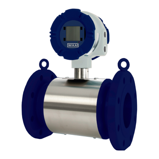
- Page 1 Operating Instructions Ultrasonic Flowmeter FLC-UFL Series Ultrasonic Flowmeter FLC-UFL...
- Page 2 Ultrasonic Flowmeter FLC-UFL Series Page 3 - 20 Additional languages available on www.wika.com Prior to starting any work, read the operating instructions! Keep for later use! WIKA Operating Instructions - Ultrasonic Flowmeter FLC-UFL...
-
Page 3: Table Of Contents
......11 5.3 Wiring of the FLC-UFL Series ......12 5.3.1 Determining installed option boards . - Page 4 9.2 Shipping & Storage ......17 Appendix A: Diagnostic Codes WIKA Operating Instructions - Ultrasonic Flowmeter FLC-UFL...
-
Page 5: Introduction
1. Introduction This manual provides information about the installation, Euromisure shall have no obligation if: operation and maintenance of the FLC-UFL series ultrasonic Repair or replacement of equipment or parts has ■ gas flowmeter. It contains information for correct operation been required through normal wear and tear, or due to and maintenance of this product. -
Page 6: Important Information
Do not remove any transducers 3.6 Cleaning or parts from the flowbody whilst the flowmeter Only clean the FLC-UFL series ultrasonic flowmeter with a is under pressure. Flammable gas can escape damp cloth. Do not use solvents for cleaning. -
Page 7: Flc-Ufl Series Product Description
Changes in the sound velocity caused by pressure or temperature fluctuations do not affect the calculated gas velocity with this measurement method. The FLC-UFL series ultrasonic gas flowmeter calculates the volume flow rate based on the gas velocity and the Flowbody internal diameter. -
Page 8: Nameplate
Pressure and temperature range ■ 4.3.1 Ground screw Mechanical design parameters (design code, design ■ pressure and temperature) A ground screw is provided to connect the FLC-UFL series Sizing and weight flowmeter to ground / earth. ■ Serial numbers ■... -
Page 9: Slot 1 - Rs485 Option Board Terminals (01-0020 / Tip007)
4.3.6 SLOT 2 - P/T Option Board (01-0022 / TIP008) / TIP007) In addition, the FLC-UFL series flowmeter can be fitted with Optionally the FLC-UFL series flowmeter can be fitted with an an optional Pressure / Temperature board, extending the I/O option board, extending the functionality of the system. -
Page 10: Slot 2 - 4
4.5 Display and keypad When equipped with this option board, a passive (externally The front of the FLC-UFL series electronics is equipped with powered) mA output is available. The output is software a graphical 128x128 dot matrix LCD graphic display. -
Page 11: Installation
Any thermowell should be positioned 3 – 5 diameters away from meter flanges. ■ ATTENTION! The installation orientation of the FLC-UFL series flowmeter is expected to be horizontal. Always consult with Euromisure for vertical installation requirements. WIKA Operating Instructions - Ultrasonic Flowmeter FLC-UFL... -
Page 12: Wiring Of The Flc-Ufl Series
Differential RS485 two D1_B RS485 B In order to determine which option boards are installed wire communications in your FLC-UFL series flowmeter, locate the FLC-UFL port, galvanically D1_A RS485 A Electronics model number on the nameplate of the SPU. isolated... -
Page 13: Slot 2, 4
6.2 Connecting to the USB Service port To connect to the FLC-UFL series via the USB Service port it may be necessary to put the FLC-UFL series flowmeter in USB Service mode. When the communication mode is set to the RS485 port, the USB Service mode enables to temporarily interface via the USB port. -
Page 14: Operation Of The Local User Interface
7. Operation of the local user interface 7.1 LED indicators 7.3 Normal operating mode screens The FLC-UFL series flowmeter has two LED indicators, During normal operation the FLC-UFL series flowmeter located underneath the LC Display. provide the essential information on areas on the LCD. -
Page 15: Main Menu
<ENT> a pattern will be in section 8: Maintenance. scanned across the display to test all pixels. Pressing <ESC> will return to the normal operating After the test the display will revert to the Operation Mode. display. WIKA Operating Instructions - Ultrasonic Flowmeter FLC-UFL... -
Page 16: Usb Service Mode
The dedicated software can be used to communicate via the USB port when in USB service mode. 8. Maintenance The FLC-UFL series ultrasonic flowmeter contains no moving of ultrasonic signals may occur. The performance indicator parts. The sensors and electronics are virtually maintenance is available for each path. -
Page 17: Signal To Noise Ratio (Snr Ab And Snr Ba)
0 °C and + 60 °C. If the FLC-UFL series flowmeter needs to be stored for a The inside of the Flowbody should be protected certain period of time before installation, the following storage... -
Page 18: Appendix A: Diagnostic Codes
Temperature sensor error or value out of range 0x00000020 PressureOutofRangeError Pressure sensor error or value out of range 0x00000040 PTReadTimeOutError No response from PT option board 0x00000080 PTZInputsOutofRangeError PTZ inputs out of range WIKA Operating Instructions - Ultrasonic Flowmeter FLC-UFL... - Page 19 0x00040000 262144 WetGasVOS Wetgas filter triggered substitution based on VOS 0x00080000 524288 WetGasVOG Wetgas filter triggered substitution based on VOG 0x00100000 1048576 Substitution Path being substituted based on historical data 0x00200000 2097152 SPARE WIKA Operating Instructions - Ultrasonic Flowmeter FLC-UFL...
- Page 20 Ultrasonic Flowmeter FLC-UFL Series For WIKA branches worldwide, visit our website www.wika.com. Euromisure s.a.s di WIKA Italia S.r.l via Borghisani 4 26035 Pieve San Giacomo (CR) - Italy Telefon (+39) 0375 6404 Telefax (+39) 0372 640490 E-Mail salesflow.it@wika.com www.wika.com WIKA Operating Instructions - Ultrasonic Flowmeter FLC-UFL...
Need help?
Do you have a question about the FLC-UFL Series and is the answer not in the manual?
Questions and answers