WIKA SENSeOR AMS01 User Manual
24/7 asset monitoring solution energy
Hide thumbs
Also See for SENSeOR AMS01:
- User manual (29 pages) ,
- User manual (28 pages) ,
- Operating instructions manual (112 pages)
Table of Contents
Advertisement
Quick Links
Document revision: UM00403EN-AA
Date: 2023-01
24/7 ASSET MONITORING SOLUTION ENERGY
AMS01 USER MANUAL
SENSeOR (head office)
Bâtiment Natura 2
1198, avenue du Docteur
Maurice Donat
06250 Mougins
France
Contact address:
support.senseor@wika.com
Regional distributors
Visit
www.senseor.com
for
the latest distribution
locations.
Advertisement
Table of Contents

Related Manuals for WIKA SENSeOR AMS01


Summary of Contents for WIKA SENSeOR AMS01
- Page 1 Document revision: UM00403EN-AA Date: 2023-01 24/7 ASSET MONITORING SOLUTION ENERGY AMS01 USER MANUAL SENSeOR (head office) Bâtiment Natura 2 1198, avenue du Docteur Maurice Donat 06250 Mougins France Contact address: support.senseor@wika.com Regional distributors Visit www.senseor.com the latest distribution locations.
-
Page 2: Warranty
MONITORING SOLUTION ENERGY WARRANTY These products are warranted to be free from functional defects in material and in workmanship at the time of the manufacturing and to conform at that time to the specifications set forth in the relevant instruction manuals or in the data sheets, for such products for a period of one year. Reference SENSeOR terms and conditions provided at time of purchase for complete warranty details. -
Page 3: Table Of Contents
MONITORING SOLUTION ENERGY TABLE OF CONTENTS WARRANTY .............................. 2 TABLE OF CONTENTS ..........................3 SAFETY INSTRUCTIONS ..........................5 CONVENTIONS ......................... 5 SAFETY INFORMATIONS ......................6 OVERVIEW ............................... 7 AVAILABLE PRODUCTS ......................7 INSTRUCTIONS FOR USE ......................7 READER OVERVIEW ......................... 8 1.2.1 SIGNAGE LABEL ........................ - Page 4 MONITORING SOLUTION ENERGY 1.8.4 BUS LENGTH ........................18 1.8.5 NUMBER OF READERS ....................18 1.8.6 MODBUS-RTU DEFAULT CONFIGURATION ..............18 1.8.7 CABLING FOR ETHERNET COMMUNICATION ..............19 ENVIRONMENTAL SENSOR CONNECTION ................19 1.10 CONNECTING TO EARTH ......................20 1.11 CONNECTING RF ANTENNAS ....................20 SYSTEM INSTALLATION AND CONFIGURATION ..................
-
Page 5: Safety Instructions
MONITORING SOLUTION ENERGY SAFETY INSTRUCTIONS IT IS IMPORTANT TO READ THIS MANUAL BEFORE INSTALLING OR COMMISSIONING SENSEOR CRITICAL MONITORING SYSTEM ASSETS. CONVENTIONS DANGER DANGER INDICATES AN IMMINENTLY HAZARDOUS SITUATION, WHICH, IF NOT AVOIDED, WILL RESULT IN DEATH OR SERIOUS INJURY. FAILURE TO FOLLOW THE INSTRUCTIONS GIVEN WILL RESULT IN DEATH OR SERIOUS INJURY. -
Page 6: Safety Informations
MONITORING SOLUTION ENERGY SAFETY INFORMATIONS Protect product from moisture and humidity. ► Protect product from too high or too low temperature (see Technical data, p. 28). ► Protect product from fire. ► Do not paint the product. ► Do not modify or disassemble the product. Service must be carried out by SENSeOR. ►... -
Page 7: Overview
MONITORING SOLUTION ENERGY OVERVIEW This reader is dedicated to switchgear monitoring with wireless passive SAW temperature sensors and UHF partial discharge detection. It is designed for interrogation inside metallic cavities like the switchgear cabinet and tuned to be compliant with IEC 62271 enabling a license-free use in switchgear worldwide. -
Page 8: Reader Overview
MONITORING SOLUTION ENERGY READER OVERVIEW Included in scope of delivery: • AMS01 reader. • User manual. • Micro SD card. • 1x 2-pin power connector. • 1x 4-pin environmental sensor connector. • 1x 2-pin relay connector. • 1x 35 mm DIN rail mount with 2x M3x6mm screws. 1.2.1 SIGNAGE LABEL Figure 1: Product signage label 1.2.2 FRONT LABEL... -
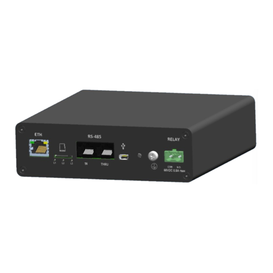
Page 9: Connectors And Functions
MONITORING SOLUTION ENERGY CONNECTORS AND FUNCTIONS Figure 3: Rear connection view 1.3.1 INPUT POWER (1) Type Description 1 (left) +24VDC Main power supply input (24VDC) 2 (right) Ground WARNING DO NOT REVERSE THE POWER SUPPLY POLARITY, THIS MAY CAUSE ELECTRICAL DAMAGE. 1.3.2 ENVIRONMENTAL SENSOR (2) Type Description... -
Page 10: Modbus Rs485 (4)
MONITORING SOLUTION ENERGY Figure 4: Front connection view 1.3.4 MODBUS RS485 (4) Type Description 1 (left) Not used Not used Not used Data + Data - Not used Not used 8 (right) Ground 1.3.5 RELAY OUTPUT (5) Type Description 1 (left) Common for relay 2 (right) N.O. -
Page 11: Status Led
MONITORING SOLUTION ENERGY STATUS LED The status led is used to indicate the functional state of reader. 1.4.1 DFU MODE LEDS INDICATION (DEVICE FIRMWARE UPGRADE) DFU is an AMS01 internal recovery/update program mode automatically called during firmware update process. Following table indicates reader status in this mode. Description LED1 status LED2 status... -
Page 12: Installation
MONITORING SOLUTION ENERGY INSTALLATION IMPORTANT THE INSTALLATION INSTRUCTIONS ARE ONLY FOR THE AMS01 READER. IT IS ASSUMED THAT SAW TEMPERATURE SENSORS AND PARTIAL DISCHARGE PROBE ANTENNAS HAVE BEEN CONFIGURED AND INSTALLED. WARNING PROFESSIONAL INSTALLATION REQUIRED. INSTALLATION AND CONFIGURATION SHOULD BE PERFORMED ONLY BY USERS WHO ARE TECHNICALLY COMPETENT AND AUTHORIZED TO DO SO. -
Page 13: Unpacking
MONITORING SOLUTION ENERGY UNPACKING 1.5.1 PHYSICAL DIMENSIONS Unit in mm. Figure 5: Reader dimensions views DIN RAIL MOUNTING CAUTION ENSURE THAT THE LOW-LEVEL COMPARTMENT WHERE THE READER IS MOUNTED IS SUFFICIENTLY VENTILATED TO PREVENT OVERHEATING. THE DEVICE MUST BE ELECTRICALLY GROUNDED FOR EMC COMPLIANCE. The reader is designed for installation on a grounded 35 mm DIN rail. -
Page 14: Reader Emplacement
MONITORING SOLUTION ENERGY 1.6.1 READER EMPLACEMENT The reader is intended to be installed in the low voltage compartment of the switchgear. The other electrical assets are recommended to be weather protected in an enclosed location. The reader is required to be installed within a maximum distance of 10 meters from the antennas, corresponding to the maximum length of the antenna cable for SAW temperature sensors and partial discharge measurement. -
Page 15: Wiring
MONITORING SOLUTION ENERGY WIRING POWER The reader power connector is a 2-pin male connector. This screw connector supports from 16 to 26 AWG wires. It is recommended to use connector ferrules on the termination of electrical conductors. 1.7.1 INPUT POWER The reader operates at 24VDC nominal with a total power consumption of 6 Watts. -
Page 16: Relay Output
MONITORING SOLUTION ENERGY 1.7.2 RELAY OUTPUT Output relay connections are recommended to be at a minimum of 16 AWG and tin-coated, with a soft drawn copper of ASTM B8, Class B stranding, 300V rated. Insulation shall be EP (Ethylene Propylene) or EPCP (Ethylene Propylene Chlorosulfonated Polyethylene compound). -
Page 17: Communication Connections
MONITORING SOLUTION ENERGY COMMUNICATION CONNECTIONS The components are used to connect Modbus devices, energy communication systems and industrial equipment with each other and to SCADA or cloud systems. The reader could be connected to a network using RS485 Modbus-RTU or Ethernet Modbus-TCP. 1.8.1 CABLING FOR RS485 COMMUNICATION SENSeOR recommends the use of shielded cable for the RS485 wiring, providing at least one twisted pair, one single line, and a drain wire. -
Page 18: Bus Data Rate
MONITORING SOLUTION ENERGY 1.8.3 BUS DATA RATE The RS485 bus data rate is dependent on the bus cable length and the number of readers on the bus. In industrial environments, slower data communication rates are generally more reliable. 1.8.4 BUS LENGTH Bus cable length has an impact on the overall data rates that can be achieved. -
Page 19: Cabling For Ethernet Communication
MONITORING SOLUTION ENERGY 1.8.7 CABLING FOR ETHERNET COMMUNICATION SENSeOR recommends the use of shielded Cat 5e SFTP cable for the Ethernet wiring, with copper cable and aluminum shielding, providing real improvement to electromagnetic interferences. Readers Ethernet network is provided by a fixed configuration more detailed below. Firstly, the IP address is defined by the last four digits of the product serial number printed on the side of the reader. -
Page 20: Connecting To Earth
MONITORING SOLUTION ENERGY 1.10 CONNECTING TO EARTH Ground lug Earth connections must be done using ground lug with a minimum of 16 AWG and tin-coated, with a soft drawn copper of ASTM B8, Class B stranding, 300V rated cable. Insulation shall be EP (Ethylene Propylene) or EPCP (Ethylene Propylene Chlorosulfonated Polyethylene compound). -
Page 21: System Installation And Configuration
MONITORING SOLUTION ENERGY SYSTEM INSTALLATION AND CONFIGURATION 1.12 SAW TEMPERATURE SENSORS INSTALLATION This manual does not cover all specific SAW temperature sensors installation. For more details, see the ‘SENSeOR Installation Manual’. 1.13 SYSTEM CONFIGURATION The reader requires a system configuration for the associated installed SAW temperature sensors, the ambient humidity and temperature sensors and the partial discharge probe antennas. -
Page 22: Reset
MONITORING SOLUTION ENERGY 1.14.2 RESET Only Ethernet settings are lost (back to default value) when device is reset. ► Hold the Reset button until all LEDs are flashing green. This can take up to 15 seconds. ► Release the Reset button. ►... -
Page 23: System Integration
MONITORING SOLUTION ENERGY SYSTEM INTEGRATION The reader support RS485 Modbus slave communication. It can be connected to an existing SCADA or PLC. 1.15 MODBUS REGISTERS Register Min. Max. Description Data type Error value Meaning address value value INPUT REGISTERS (READ ONLY) SAW TEMPERATURE SENSOR MEASUREMENTS SAW DATA 1 (1-1) 30001... - Page 24 MONITORING SOLUTION ENERGY SAW DATA 32 30032 SAW DATA 33 30033 SAW DATA 34 30034 SAW DATA 35 30035 SAW DATA 36 30036 SAW DATA 37 (5-1) 30037 SAW DATA 38 30038 SAW DATA 39 30039 SAW DATA 40 30040 Antenna 5 SAW DATA 41 30041...
- Page 25 MONITORING SOLUTION ENERGY Major version 39031 Minor verison 39032 Software Patch version 39033 Type version 39034 Unsigned 65535 Major verison 39035 Modbus register Minor verison 39036 Patch version 39037 HOLDING REGISTERS SYSTEM CONFIGURATION Address 40001 Unsigned Reader S/N + 1 Baudrate code 40002 Unsigned...
- Page 26 MONITORING SOLUTION ENERGY Table 1: Reader product register interpretation Model Description AMS01-T Temperature monitoring only AMS01-P Partial discharge monitoring only AMS01-TP Temperature and partial discharge monitoring Table 2: Modbus baudrate register interpretation Register value Baudrate 9 600 19 200 (default value) 38 400 57 600 115 200...
- Page 27 MONITORING SOLUTION ENERGY Table 5: Partial discharge indicator interpretation values Register value Configuration No presence Presence Warning Alert SENSeOR AMS01 User Manual 27/29 www.senseor.com...
-
Page 28: Specifications
MONITORING SOLUTION ENERGY SPECIFICATIONS RS485 COMMUNICATION INTERFACE Protocol Modbus-RTU Supported baud rates 9 600, 19 200, 38 400, 57 600, 115 200 ETHERNET COMMUNICATION INTERFACE Protocols Modbus-TCP, SENSeOR proprietary for configuration Supported speed 10/100 Mbit/s TEMPERATURE MEASUREMENT Number of antenna pairs Number of configurable SAW Up to 30 –... -
Page 29: Product Certifications
MONITORING SOLUTION ENERGY PRODUCT CERTIFICATIONS 1.16 CERTIFICATIONS RoHS 2011/65/EU and 2015/863/EU IEC 62271-1: Switchgear, CISPR11 IEC 61000-4-2, IEC 61000-4-4, IEC 61000-4-17 IEC 61000-4-18, IEC 61000-4-29 IEC 60068-2-1, IEC 60068-2-2, IEC 60068-2-6, IEC 60068-2-30 IEC 60068-2-6, IEC 60068-2-78 IEC 60255-21-1, IEC 60255-21-3 IEC 61010-1 CEPRI-EETC06-2019-0023 / CCAM19LP1860T6 SENSeOR...
Need help?
Do you have a question about the SENSeOR AMS01 and is the answer not in the manual?
Questions and answers