WIKA SENSEOR AMS01 User Manual
24/7 asset monitoring solution
Hide thumbs
Also See for SENSEOR AMS01:
- User manual (29 pages) ,
- User manual (29 pages) ,
- Operating instructions manual (112 pages)
Table of Contents
Advertisement
Quick Links
Document revision: UM00403EN-AC
Date: 2023-08
24/7 ASSET MONITORING SOLUTION
AMS01 USER MANUAL
SENSeOR (head office)
Bâtiment Natura 2
1198, avenue du Docteur
Maurice Donat
06250 Mougins
France
Contact address:
support.senseor@wika.com
Regional distributors
Visit
www.senseor.com
for
the latest distribution
locations.
Advertisement
Table of Contents

Subscribe to Our Youtube Channel
Related Manuals for WIKA SENSEOR AMS01


Summary of Contents for WIKA SENSEOR AMS01
- Page 1 Document revision: UM00403EN-AC Date: 2023-08 24/7 ASSET MONITORING SOLUTION AMS01 USER MANUAL SENSeOR (head office) Bâtiment Natura 2 1198, avenue du Docteur Maurice Donat 06250 Mougins France Contact address: support.senseor@wika.com Regional distributors Visit www.senseor.com the latest distribution locations.
-
Page 2: Warranty
24/7 ASSET MONITORING SOLUTION UM00403EN-AC WARRANTY These products are warranted to be free from functional defects in material and in workmanship at the time of the manufacturing and to conform at that time to the specifications set forth in the relevant instruction manuals or in the data sheets, for such products for a period of one year. -
Page 3: Table Of Contents
24/7 ASSET MONITORING SOLUTION UM00403EN-AC TABLE OF CONTENTS WARRANTY .............................. 2 TABLE OF CONTENTS ..........................3 SAFETY INSTRUCTIONS ..........................5 CONVENTIONS ......................... 5 SAFETY INFORMATIONS ......................6 OVERVIEW ............................... 7 RELATED DOCUMENTS ......................7 AVAILABLE PRODUCTS ......................7 INSTRUCTIONS FOR USE ......................8 READER OVERVIEW ......................... - Page 4 24/7 ASSET MONITORING SOLUTION UM00403EN-AC 1.8.2 RELAY OUTPUT ......................20 1.8.3 INTERNAL BATTERY ....................... 20 COMMUNICATION CONNECTIONS ..................21 1.9.1 CABLING FOR RS485 COMMUNICATION ............... 21 1.9.2 BUS RESISTIVE TERMINATION ..................21 1.9.3 BUS DATA RATE ......................22 1.9.4 BUS LENGTH ........................22 1.9.5 NUMBER OF READERS ....................
-
Page 5: Safety Instructions
24/7 ASSET MONITORING SOLUTION UM00403EN-AC SAFETY INSTRUCTIONS IT IS IMPORTANT TO READ THIS MANUAL BEFORE INSTALLING OR COMMISSIONING SENSEOR ASSETS MONITORING SYSTEM. CONVENTIONS DANGER DANGER INDICATES AN IMMINENTLY HAZARDOUS SITUATION, WHICH, IF NOT AVOIDED, WILL RESULT IN DEATH OR SERIOUS INJURY. FAILURE TO FOLLOW THE INSTRUCTIONS GIVEN WILL RESULT IN DEATH OR SERIOUS INJURY. -
Page 6: Safety Informations
24/7 ASSET MONITORING SOLUTION UM00403EN-AC SAFETY INFORMATIONS ► Protect product from moisture and humidity. ► Protect product from too high or too low temperature. ► Protect product from fire. ► Do not paint the product. ► Do not modify or disassemble the product. Service must be carried out by SENSeOR. ►... -
Page 7: Overview
24/7 ASSET MONITORING SOLUTION UM00403EN-AC OVERVIEW CAUTION THIS READER IS DEDICATED TO SWITCHGEAR MONITORING WITH WIRELESS PASSIVE SAW TEMPERATURE SENSORS, ENVIRONMENTAL SENSOR AND UHF PARTIAL DISCHARGE DETECTION. IT IS DESIGNED FOR USE INSIDE METALLIC CAVITIES ONLY LIKE THE SWITCHGEAR CABINET AND TUNED TO BE COMPLIANT WITH IEC 62271 ENABLING A LICENSE-FREE USE IN SWITCHGEAR WORLDWIDE. -
Page 8: Instructions For Use
24/7 ASSET MONITORING SOLUTION UM00403EN-AC INSTRUCTIONS FOR USE The AMS01 reader is dedicated to monitor electrical equipment like switchgears. The temperature of live conductors is measured by SAW sensors and prevent overheating and overload. Partial discharges are measured by antenna pairs and prevent equipment failure. Ambient temperature and humidity measurements are also available through an optional environmental sensor connected with wires to... -
Page 9: Reader Overview
24/7 ASSET MONITORING SOLUTION UM00403EN-AC READER OVERVIEW Included in scope of delivery: 1x AMS01 reader. 1x AMS01 system user manual. 1x µSD card. 1x 2-pin power connector. 1x 4-pin environmental sensor connector. 1x 2-pin relay connector. 1x 35 mm DIN rail mount with 2x M3x6 mm screws. 1.3.1 SERIALIZATION LABEL Figure 1: Product serialization label 1.3.2 FRONT LABELS... -
Page 10: Connectors & Functions
24/7 ASSET MONITORING SOLUTION UM00403EN-AC CONNECTORS & FUNCTIONS Figure 3: Rear connection view 1.4.1 INPUT POWER (1) Type Description 1 (left) +24VDC Main power supply input (24VDC 0.2A) 2 (right) Ground CAUTION DO NOT REVERSE THE POWER SUPPLY POLARITY, THIS MAY CAUSE ELECTRICAL DAMAGE. 1.4.2 ENVIRONMENTAL SENSOR (2) Type Description... -
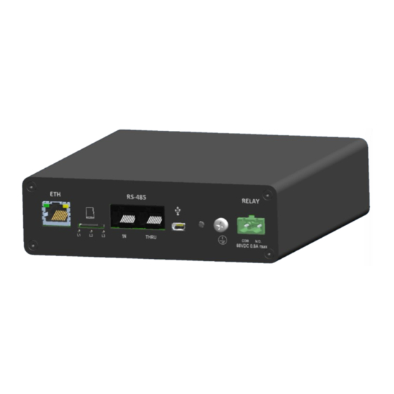
Page 11: Ethernet Port (4)
24/7 ASSET MONITORING SOLUTION UM00403EN-AC Figure 4: Front connection view 1.4.4 ETHERNET PORT (4) Standard RJ45 socket for Modbus-TCP communication and reader configuration. Type Description Tx + Transmit data + Tx - Transmit data - Rx + Receive data + Not used Not used Rx -... -
Page 12: Rs485 Ports (6)
24/7 ASSET MONITORING SOLUTION UM00403EN-AC 1.4.6 RS485 PORTS (6) RJ45 ports for Modbus-RTU communication. Type Description 1 (left) Not used Not used Not used Data + Data - Not used Not used 8 (right) Ground Figure 6: RS485 socket pinout 1.4.7 USB PORT (7) Mini USB port reserved for future use. -
Page 13: Status Leds
24/7 ASSET MONITORING SOLUTION UM00403EN-AC STATUS LEDS Status LEDs are used to indicate the functional state of reader. 1.5.1 DFU MODE LEDS INDICATION (DEVICE FIRMWARE UPGRADE) DFU is an AMS01 internal recovery/update program mode automatically called during firmware update process. Following table indicates reader status in this mode. -
Page 14: Applicative Mode Leds Indication
24/7 ASSET MONITORING SOLUTION UM00403EN-AC 1.5.2 APPLICATIVE MODE LEDS INDICATION 1.5.2.1 LED 1 (L1) indication description Description Status No power LED OFF System is working properly LED ON System warning LED ON System error LED ON 1.5.2.2 LED 2 (L2) indication description Description Status No notifier configured... -
Page 15: Installation
24/7 ASSET MONITORING SOLUTION UM00403EN-AC INSTALLATION IMPORTANT THE INSTALLATION INSTRUCTIONS ARE ONLY FOR THE AMS01 READER. IT IS ASSUMED THAT SAW TEMPERATURE SENSORS AND PARTIAL DISCHARGE PROBE ANTENNAS HAVE BEEN CONFIGURED AND INSTALLED. WARNING PROFESSIONAL INSTALLATION REQUIRED. INSTALLATION AND CONFIGURATION SHOULD BE PERFORMED ONLY BY USERS WHO ARE TECHNICALLY COMPETENT AND AUTHORIZED TO DO SO. -
Page 16: Unpacking
24/7 ASSET MONITORING SOLUTION UM00403EN-AC UNPACKING 1.6.1 PHYSICAL DIMENSIONS Unit in mm. Figure 8: Reader dimensions views SENSeOR AMS01 User Manual 16/28 www.senseor.com... -
Page 17: Din Rail Mounting
24/7 ASSET MONITORING SOLUTION UM00403EN-AC DIN RAIL MOUNTING CAUTION ENSURE THAT THE LOW-LEVEL COMPARTMENT WHERE THE READER IS MOUNTED IS SUFFICIENTLY VENTILATED TO PREVENT OVERHEATING. THE DEVICE MUST BE ELECTRICALLY GROUNDED FOR EMC COMPLIANCE. The reader is designed for installation on a grounded 35 mm DIN rail. The reader could be mounted in two different positions to facilitate integration. -
Page 18: Reader Emplacement
24/7 ASSET MONITORING SOLUTION UM00403EN-AC 1.7.1 READER EMPLACEMENT The reader is intended to be installed in the low voltage compartment of the switchgear. The other electrical assets are recommended to be weather protected in an enclosed location. Figure 11: Reader emplacement in switchgear The reader is required to be installed within a maximum distance of 10 meters from the antennas, corresponding to the maximum length of the antenna coaxial cable for SAW temperature sensors and partial discharge measurement. -
Page 19: Wiring
24/7 ASSET MONITORING SOLUTION UM00403EN-AC WIRING POWER The reader power connector is a 2-pin male connector. This screw connector supports from 16 to 26 AWG wires. For stranded conductor use connector ferrules on the termination. Figure 13: Connector ferrule 1.8.1 INPUT POWER The reader operates at 24VDC nominal with a total power consumption of 6 Watts maximum. -
Page 20: Relay Output
24/7 ASSET MONITORING SOLUTION UM00403EN-AC 1.8.2 RELAY OUTPUT Output relay connections are recommended to be at a minimum of 16 AWG. 1.8.3 INTERNAL BATTERY SENSeOR reader has an internal 3VDC non rechargeable battery to keep the UTC date and the time in case of power down. -
Page 21: Communication Connections
24/7 ASSET MONITORING SOLUTION UM00403EN-AC COMMUNICATION CONNECTIONS The components are used to connect Modbus devices, energy communication systems and industrial equipment with each other and to SCADA or cloud systems. The reader could be connected to a network using RS485 Modbus-RTU or Ethernet Modbus-TCP. 1.9.1 CABLING FOR RS485 COMMUNICATION SENSeOR recommends the use of shielded cable for the RS485 wiring, providing at least one twisted pair, one single line, and a drain wire. -
Page 22: Bus Data Rate
24/7 ASSET MONITORING SOLUTION UM00403EN-AC 1.9.3 BUS DATA RATE The RS485 bus data rate is dependent on the bus cable length and the number of readers on the bus. In industrial environments, slower data communication rates are generally more reliable. 1.9.4 BUS LENGTH Bus cable length has an impact on the overall data rates that can be achieved. -
Page 23: Cabling For Ethernet Communication
24/7 ASSET MONITORING SOLUTION UM00403EN-AC 1.9.7 CABLING FOR ETHERNET COMMUNICATION SENSeOR recommends the use of shielded Cat 5e SFTP cable for the Ethernet wiring. Readers Ethernet network is provided by a fixed configuration more detailed below. The IP address is defined by the last four digits of the product serial number printed on the side of the reader. -
Page 24: Connecting To Earth
24/7 ASSET MONITORING SOLUTION UM00403EN-AC 1.11 CONNECTING TO EARTH Ground lug Figure 19: Reader ground lug cabling Earth connections must be done using ground lug with a minimum of 16 AWG with ring terminal. 1.12 CONNECTING RF ANTENNAS Antenna installation should respect following pattern. Two antennas by compartment connected to the reader using A and B output connectors. -
Page 25: System Installation And Configuration
24/7 ASSET MONITORING SOLUTION UM00403EN-AC SYSTEM INSTALLATION AND CONFIGURATION 1.13 SAW TEMPERATURE SENSORS INSTALLATION This manual does not cover all specific SAW temperature sensors installation. 1.14 SYSTEM CONFIGURATION The reader requires a system configuration for the associated installed SAW temperature sensors, the ambient humidity and temperature sensors and the partial discharge probe antennas. -
Page 26: Sd Card
24/7 ASSET MONITORING SOLUTION UM00403EN-AC 1.16 SD CARD A µSD HC memory card is inserted into the reader and will save all measurements locally. Please refer to the document ‘UM00419EN-AA_AMS01 SD card file management’ for more information about the files and data format. SENSeOR recommends to use a 8 Gb µSD card capacity to store a sufficient amount of data. -
Page 27: Network Parameters Reset
24/7 ASSET MONITORING SOLUTION UM00403EN-AC 1.16.1 NETWORK PARAMETERS RESET WARNING ONLY ETHERNET SETTINGS ARE LOST (BACK TO DEFAULT VALUES) WHEN DEVICE IS RESET. ► Hold the Reset button until all LEDs are flashing green. This can take up to 15 seconds. ►... -
Page 28: Certifications
24/7 ASSET MONITORING SOLUTION UM00403EN-AC CERTIFICATIONS 1.17 CERTIFICATIONS RoHS 2011/65/EU and 2015/863/EU IEC 62271-1: Switchgear, CISPR11 IEC 61000-4-2, IEC 61000-4-4, IEC 61000-4-17 IEC 61000-4-18, IEC 61000-4-29 IEC 60068-2-1, IEC 60068-2-2, IEC 60068-2-6, IEC 60068-2-30 IEC 60068-2-6, IEC 60068-2-78 IEC 60255-21-1, IEC 60255-21-3 IEC 61010-1 SENSeOR AMS01 User Manual...
Need help?
Do you have a question about the SENSEOR AMS01 and is the answer not in the manual?
Questions and answers