Table of Contents
Advertisement
Quick Links
Advertisement
Chapters
Table of Contents

Subscribe to Our Youtube Channel
Related Manuals for EXFO CT440


Summary of Contents for EXFO CT440
- Page 1 User Guide CT440 Optical Component Tester www.EXFO.com...
-
Page 2: Copyright
Information provided by EXFO is believed to be accurate and reliable. However, no responsibility is assumed by EXFO for its use nor for any infringements of patents or other rights of third parties that may result from its use. No license is granted by implication or otherwise under any patent rights of EXFO. -
Page 3: Table Of Contents
Connecting the CT440 to a Power Source ......................21 Setting Up your Computer ..........................22 Starting/Stopping the CT440 ..........................23 4 Setting Up Your CT440 and Performing Measurement Scans ..........27 Connecting and Configuring the Tunable Laser(s) .....................27 Configuring the CT440 for Measurements ......................31 Performing User Referencing ..........................34... - Page 4 Activating the USB Driver ..........................152 Contacting the Technical Support Group ......................152 Transportation ..............................153 10 Warranty ..........................155 General Information ............................155 Gray Market and Gray Market Products ......................155 Liability ................................156 Exclusions ................................156 Certification ..............................156 Service and Repairs ............................157 EXFO Service Centers Worldwide ........................158 CT440...
-
Page 5: Regulatory Information
USA Electromagnetic Interference Regulatory Statement Electronic test and measurement equipment is exempt from FCC part 15, subpart B compliance in the United States of America. However, EXFO Inc. makes reasonable efforts to ensure compliance to the applicable standards. The limits set by these standards are designed to provide reasonable protection against harmful interference when the equipment is operated in a commercial environment. - Page 6 EU and UK Declaration of Conformity The full text of the declaration of conformity is available at the following Internet address: www.exfo.com/en/resources/legal-documentation. EU Economic Operator EXFO Solutions SAS 2, rue Jacqueline Auriol, Saint-Jacques-de-la-Lande, 35091 Rennes Cedex 9 FRANCE...
-
Page 7: Introducing The Ct440
It covers the specified transmission band in one run. The CT440 provides the transmission function (TF) of the device under test (DUT) with the help of one or more sweeping laser sources. It identifies and switches, from one port to the next, the available laser sources to go through a common output port in order to use a multi TLS source as a unique (usually very wide band) source. - Page 8 (DUT). The technique relies on collecting spectral data for each of either 4 or 6 polarization state conditions (one sweep by state), before calculating both TF and PDL. One to four optical detectors enable the CT440 to provide the direct TF and PDL (if available) of the DUT.
- Page 9 CT440 Optical Component Tester. You can use the instructions related to the use of the CT440 Optical Component Tester GUI and CT440 Optical Component Tester library given in the present CT440 User Guide; they apply to the last version of the software whatever the CT440 Optical Component Tester hardware version.
- Page 10 Polarization State Generator (only on CT440 Optical Component Tester with PDL option) On CT440 Optical Component Tester with PDL option, the signal passes through a polarization state generator (PSG) that produces one of 6 states of polarization at the output port.
- Page 11 Product Features Detection System One to four optical detectors enable the CT440 Optical Component Tester to provide the direct TF and PDL (if available) of the DUT with up to four outputs. The additional electrical input port (Analog In BNC at the rear of the instrument) can...
- Page 12 The CT440 Optical Component Tester checks most of these behaviors and issues a warning in non standard running configurations. Supported TLS...
-
Page 13: Technical Specifications
Optical Measurement Specifications MPORTANT The following technical specifications can change without notice. The information presented in this section is provided as a reference only. To obtain this product’s most recent technical specifications, visit the EXFO Web site at www.exfo.com. PM13 PM15 PDL-O... - Page 14 Windows 10 requirements Interface with TLS GPIB interface card to TLS Interface with CT440 USB-A 2.0 port to CT440 Physical Specifications Physical Specifications Dimensions (W x H x D) 440 x 50 x 375 mm (17.3 x 2 x 14.8 in) Weight Between 3.5 kg and 3.9 kg (7.7 lb to 8.6 lb),...
-
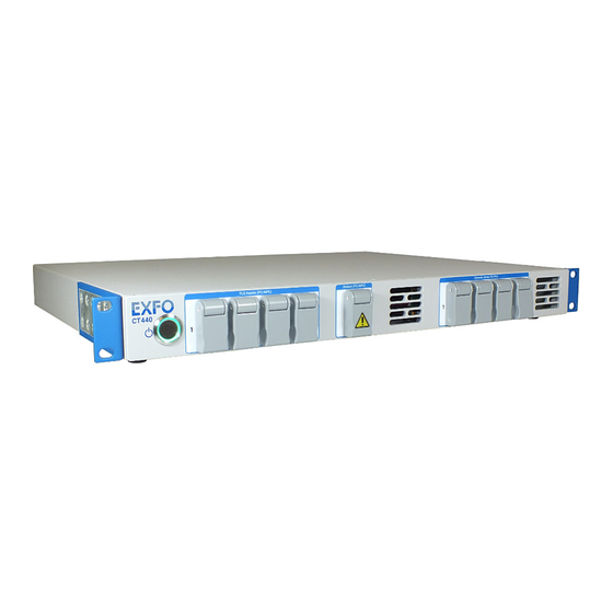
Page 15: Product Overview
The CT440 is made of two complementary parts: The CT440 instrument, which makes measurements during the wavelength scan The CT440 software (GUI), which takes the data from the instrument and performs all the analysis The CT440 is delivered with the following accessories:... - Page 16 CT440 models, PMF for PM13 and PM15 CT440 models. label indicates the location of the laser output. This output requires special safety instructions for proper use (see Connecting the DUT to the CT440 on page 39). Detector Ports The Detector Array label identifies the PC connectors used to connect the output ports of the device under test (up to four connectors depending on the model).
- Page 17 Fuse Holder The fuse holder contains two fuses (see Technical Specifications on page 7 for fuse type) to protect the CT440 from overcurrent. For details on how to replace the fuses, see Replacing Fuses on page 145). Power Cord Connector & Power Switch The CT440 unit is equipped with a self-regulating power supply (for details, see Technical Specifications on page 7).
-
Page 18: Conventions
The fuse type is described in Technical Specifications on page 7. Warranty seal Warranty void The CT440 Optical Component Tester cover must not if seal broken. be open, otherwise the warranty is not valid anymore. Conventions Before using the product described in this guide, you should understand the following... -
Page 19: Abbreviations Used
Introducing the CT440 Abbreviations Used Abbreviations Used Abbreviation Meaning Dynamic Link Library Digital Signal Processor Device Under Test Free-spectral range GPIB General Purpose Interface Bus Graphical User Interface Insertion Loss Polarization Dependent Loss Polarization Extinction Ratio Polarization State Generator Transfer Function... -
Page 21: Safety Information
If the equipment is used in a manner not specified by the manufacturer, the protection provided by the equipment may be impaired. ARNING Use only accessories designed for your unit and approved by EXFO. For a complete list of accessories available for your unit, refer to its technical specifications or contact EXFO. -
Page 22: Other Safety Symbols On Your Unit
Do not install or terminate fibers while a light source is active. Never look directly into a live fiber and ensure that your eyes are protected at all times. Laser radiation may be encountered at the optical output port. CT440... -
Page 23: Electrical Safety Information
Safety Information Electrical Safety Information Electrical Safety Information This unit uses an international safety standard three-wire power cable. This cable serves as a ground when connected to an appropriate AC power outlet. ARNING If you need to ensure that the unit is completely turned off, disconnect the power cable. - Page 24 Input power 100–240 V ; 50/60 Hz; 0.76 A max Not exceeding ± 10 % of the nominal voltage. AUTION The use of voltages higher than those indicated on the label affixed to your unit may damage the unit. CT440...
-
Page 25: Getting Started With Your Ct440
CT440 in a Rack on page 20. 4. Allow the flow of air to be pulled in freely from outside to inside the CT440 through the air inlets located on the front panel and be pushed out the instrument through the cooling fan grids on the rear. -
Page 26: Installing The Ct440 In A Rack
Installing the CT440 in a Rack Installing the CT440 in a Rack To be able to install the CT440 in a rack, you must first install the rack-mounting brackets on each side of the instrument. The brackets are delivered with eight screws (8 mm) to fasten it on each side panels of the instrument with a Phillips head screwdriver. -
Page 27: Connecting The Ct440 To A Power Source
3. Lift the CT440 to its position in the rack by holding it from below. 4. Use the rack mounting screws to attach the CT440 rack mounting brackets to the front of the rack. Connecting the CT440 to a Power Source To connect the CT440 to a wall socket: 1. -
Page 28: Setting Up Your Computer
Installing/Updating the CT440 Software Package on Your Computer The CT440 software installer is available on the USB key delivered with the CT440, or on the EXFO website (EXFO Apps). The CT440 Installer installs the following components on your computer: CT440 GUI software, with samples of traces and configuration that can be loaded in OFFLINE mode (made on a CT440-PDL PM15 with 4 detectors). -
Page 29: Starting/Stopping The Ct440
At the GUI startup with the CT440 Optical Component Tester, if the new version requires an update of the DSP code of the unit, you are prompted to upgrade the CT440 Optical Component Tester DSP. In this case, click Yes to update the DSP. - Page 30 To start the CT440 GUI software: 1. Make sure the CT440 GUI is installed and connected to your computer (see Setting Up your Computer on page 22). 2. Turn on the CT440 (see Turning On/Off the CT440 on page 23).
- Page 31 The Analysis Results tab displays the results of the analysis selected in the Analysis Parameters window. For more details, see Analyzing Traces on page 59. The Line Detection tab (only for CT440 with two or more TLS inputs) displays the results of the line wavelength measurements. For more details, see Performing Line Wavelength Measurements on page 51.
-
Page 33: Setting Up Your Ct440 And Performing Measurement Scans
Setting Up Your CT440 and Performing Measurement Scans This section explains how to connect your CT440 to external devices to perform IL and PDL (if available) measurement scans. Connecting and Configuring the Tunable Laser(s) This section explains how to connect the tunable laser(s) to computer and CT440 through GPIB or Ethernet in a standard use. - Page 34 1. Using the GPIB cable(s) or Ethernet cable, connect your computer to the TLS. 2. Using a clean APC patch cord, connect the TLS to the input port(s) of the CT440. If you want to connect two or more TLS, follow the instructions below: 2a.
- Page 35 Scan button. The Scan Parameters window appears. Example window from a CT440 with one TLS input. 3. Set parameters for the laser(s) connected to the CT440 (1 tab per connected laser), according to the instructions given in the following table. Parameter...
- Page 36 The Power Monitoring (dB) area enables you to monitor: Optical power on all the detectors Optical power at the output port of the CT440 The Voltage Monitoring (V) area enables you to monitor the voltage at the analog Analog In BNC input port on the rear panel.
-
Page 37: Configuring The Ct440 For Measurements
Red color indicates that the power and voltage values are out of specification for a proper measurement with the CT440. In this case, verify that your laser injects enough power into the CT440 and that your fiber connectors are clean (see Cleaning Optical Connectors). - Page 38 4. Click the button or anywhere on the screen outside the window to exit. To configure the scanning options: 1. Start the CT440 (see Starting/Stopping the CT440 on page 23). 2. In the main window, click the button located to the left of the Scan button.
- Page 39 The CT440 performs a scan of the wavelength range set in the Start/Stop fields and then stops. On CT440 with PDL option: if a PDL measurement is required by one or more traces (see Configuring Trace Parameters on page 41), a scan is composed of 4 or 6 successive sweeps (depending on the selected PDL Method).
-
Page 40: Performing User Referencing
You cannot zero the dark current on the Analog In BNC connector located on the rear located on the rear panel of the CT440 (see Rear Panel on page 11). To zero the detectors: 1. Make sure that no light source is connected to the detector you want to set to zero. - Page 41 If you use a splitter, the PDL measured will be affected by the PDL of the splitter itself, even after referencing. When using the CT440 GUI for the first time, the factory calibration file is created and stored on the control computer, in the appropriate Calib folder: C:\Users\Public\Documents\EXFO\CT440\Calib The file name is <serial number>.bin.
- Page 42 1. To obtain the optimum performance of the system, make sure the optical connectors are perfectly clean (see Cleaning Optical Connectors on page 144). 2. Connect a verified optical jumper between the output port of the CT440 and the detector port you want to reference.
- Page 43 2. In the Scan Parameters area, specify a wavelength range corresponding to the gas cell with a resolution setting of 1 pm (5 pm on CT440 with PDL option). 3. Click the Scan button. 4. On the graph, manually measure the wavelength for a specific absorption line.
- Page 44 You can recover the initial factory calibration at any time. Calibration reset erases all calibration modifications done on the wavelength referencing, on detector calibration and on detector zeroing. To recover the initial factory calibration: In the Referencing window, click the Reset Calibration button. All referencing operations performed on the CT440 are erased. CT440...
-
Page 45: Connecting The Dut To The Ct440
Connecting the DUT to the CT440 Connecting the DUT to the CT440 This section explains how to connect the device under test to the CT440 in a standard use. For more information on how to use the external detector, see Performing a Measurement Using the Analog In BNC Connector on page 48. - Page 46 For safe use of the CT440 output port, please respect the safety guidelines of the laser(s) connected to the CT440 input port(s). The CT440 Output port is APC type. If the DUT input is PC type, use a clean patch cord APC/PC and an adapter to interface between the CT440 and the DUT.
-
Page 47: Configuring Trace Parameters
Configuring Trace Parameters Configuring Trace Parameters The CT440 can display 8 traces. Each trace is represented by a different color. The Trace x Parameters window allows you to select the type of measurement you want the CT440 to perform for each trace. - Page 48 None: clears the trace content and deactivates the trace. Source The CT440 detector corresponding to the selected trace. Detector 1 to Detector 4 are located on the CT440 front panel (see Figure 5, p. 22). Analog In BNC connector is located on the CT440 rear panel and enables you to perform voltage or optical power measurements.
-
Page 49: Manually Starting/Stopping A Scan
4. To improve low power measurement, perform a dark current zeroing on detectors: see Zeroing the Electrical Offset on Detectors on page 34. 5. Connect the DUT to the CT440, as explained in Connecting the DUT to the CT440 on page 39. -
Page 50: Setting Up A Triggered Scan
When the TLS has reached the start wavelength, the trigger signal rises (0 to 1) and the CT440 starts collecting data. On CT440 with PDL option: if PDL measurement is selected in one of the trace menus, the CT440 measures one state of polarization (out of 4 or 6 depending on the selected parameter) at each rising edge. - Page 51 On the T100S-HP laser, you must configure the λ BNC port as a trigger output, as explained in T100S-HP User Manual. 2. In the CT440 GUI, in the Scan Parameters window (for more details, see Configuring the CT440 for Measurements on page 31): 2a.
-
Page 52: Synchronizing The Ct440 With External Measurements
The following figure illustrates the hardware setup for external TF measurements. CT440 Pulses During the scan of the laser, the CT440 generates TTL pulses at the Trigger Out BNC connector. The sequence of pulses depends on the resolution (Sampling res. (pm)) set in the Scan Parameters window: if a resolution of n pm is selected, then a trigger pulse over n pulses comes out of the CT440. - Page 53 Setting Up Your CT440 and Performing Measurement Scans Synchronizing the CT440 with External Measurements The CT440 provides a sequence of TTL pulses in the wavelength domain, so separation between pulses is not equidistant as it would be in the frequency domain.
-
Page 54: Performing A Measurement Using The Analog In Bnc Connector
Performing a Measurement Using the Analog In BNC Connector The CT440 enables you to measure an electric signal through the Analog In BNC input port during the scan. You can measure the voltage of the electric signal or the optical power of the signal. - Page 55 2. In the Trace Parameters window: 2a. In the Source list, select Analog In BNC. 2b. On CT440 with PDL option: in the Measurement list, select Voltage. 3. Start a scan (see Manually Starting/Stopping a Scan on page 43). The graph displays the measured voltage with a separated scale (in Volts) on the right axis.
- Page 56 2. In the Trace Parameters window: 2a. In the Source list, select Analog In BNC. 2b. On CT440 with PDL option: in the Measurement list, select the type of measurement you want the trace to display (Transfer function or PDL).
-
Page 57: Performing Line Wavelength Measurements
The Line detection tab provides the list of all spectral lines detected during the scan in a table. This allows you to use the CT440 as a multi-source wavemeter. It is possible to detect up to 16 spectral lines. - Page 58 Setting Up Your CT440 and Performing Measurement Scans Performing Line Wavelength Measurements To perform line wavelength measurements: 1. Connect a TLS to input port 1 and a laser source to input port 2 with an overlapped wavelength. 2. Start a measurement (see Manually Starting/Stopping a Scan on page 43).
-
Page 59: Saving/Loading Configuration Parameters
The following procedure explains how to save/load the overall configuration of the CT440. The configuration includes: All parameters set in all windows of the CT440 GUI: scan parameters, trace parameters, analysis parameters All the associated traces (in a separate folder). -
Page 61: Displaying And Operating Scan Traces On Graph
Displaying and Operating Scan Traces on Graph The graph area tab displays the scan results measured by the CT440 and enables you to manage scans and traces. The left scale in dB applies to the transfer function measurement. The right scale depends on the trace displayed on graph:... -
Page 62: Changing The Spectral Unit On Graph
Two horizontal markers (C and D) to indicate the optical power on the activated trace. The following figure describes the marker commands. Scale for PDL or voltage Scale for TF Activated measurements measurements trace Marker activation button Marker button Active trace flag Marker position value CT440... - Page 63 Displaying and Operating Scan Traces on Graph Performing Measurements with Markers To perform measurements with markers: 1. Activate the trace on which you want to position markers by clicking on its label. The trace button is circled anda colored flag appears on the corner of the activation button to indicate that the trace is brought to front and activated.
-
Page 64: Handling Traces
To activate a displayed trace, click the trace button. The trace button is circled with a colored flag on the corner. Saving/Loading Traces You can save traces in .csv, or .tra (CT440 specific format) formats To save a trace: 1. In the main window, click the button located to the left of the wanted trace button. -
Page 65: Analyzing Traces
The Analysis Parameters window displays all parameters of the analysis you can perform on traces. To define the analysis parameters: 1. Perform a measurement to display appropriate traces (see Setting Up Your CT440 and Performing Measurement Scans on page 27). 2. In the main window, click the button located to the left of the Analyze button. - Page 66 For more details on how to configure Pass Band Test parameters, Defining Pass Band Test Analysis Parameters on page 67 Stop Band Test tab For more details on how to configure Stop Band Test parameters, Defining Stop Band Test Analysis Parameters on page 72 CT440...
- Page 67 Analyzing Traces Defining the Analysis Parameters Defining Spectral Width Analysis Parameters The Spectral Width 1, Spectral Width 2 and Spectral Width 3 analysis tools are available for Pass Band Filter component analysis. They allow you to identify in a spectral trace the width of the main peak at three given thresholds below the peak power and the central wavelength.
- Page 68 The Envelope algorithm defines an envelope from the peaks of the spectrum above Mode Threshold (linear fit between each peak on log scale) and deduces the width based on that envelope, as shown in the following figure. Width Threshold Mode Threshold Wavelength or Frequency CT440...
- Page 69 Analyzing Traces Defining the Analysis Parameters RMS/RMS Peak The RMS and RMS Peak algorithms calculate the root mean square value σ of the power data above a given Width Threshold, taking the full power data (RMS) or simply the Power at Peak (RMS Peak) for the calculation. Width Threshold Wavelength or Frequency Gaussian Fit/Lorentzian Fit...
- Page 70 : the measurement includes a single peak (the main peak). Default value: Fit to Mode (only for Threshold algorithm, if Modal Analysis check-box is selected). : the calculation of width is fitted to the nearest detected peaks. (default): the calculation of width is fitted to the curve-threshold crossing. CT440...
- Page 71 Analyzing Traces Defining the Analysis Parameters Defining Notch Width Analysis Parameters The Notch Width 1, Notch Width 2 and Notch Width 3 tools are available for the stop band filter and isolator components analysis. They allow you to identify in a spectral trace the width of a trough at a given threshold above the trough power.
- Page 72 Width Reference: method used for the measurement of the width. Bottom (default): the width is calculated from the trough. Top: the width is calculated from the two surrounding peaks on either side of the notch to be analyzed. Width Threshold Bottom Width Threshold Wavelength or Frequency CT440...
- Page 73 Analyzing Traces Defining the Analysis Parameters Defining Pass Band Test Analysis Parameters The Pass Band Test tool is available for the pass band filter component analysis. It allow you to get cross-talk, average loss, ripple and roll-off characteristics for a pass band filter. To define Pass Band Test analysis parameters: 1.
- Page 74 Spectral Width 1 tool (see Spectral Width x Results on page 77). Set Distance: enables you to set the spacing via the In/Out Band Distance parameter. In Reference Width @ XdB Out Reference Out Reference Wavelength or Frequency CT440...
- Page 75 Analyzing Traces Defining the Analysis Parameters IN/OUT Band Distance (only if In/Out Band Method is set to Set Distance) Spectral spacing in nm/THz between the in-band reference point and the out-band reference points to be used for the crosstalk calculation. Default value: 1 nm Average Loss &...
- Page 76 Detection Threshold (only if Averaging Range is set to PT Detection) Threshold in dB for the detection of in-band extreme peaks over which calculations are done. The range is centered on the reference points for out-band (set in CrossTalk Settings on page 68). Default: 0.1 dB CT440...
- Page 77 Analyzing Traces Defining the Analysis Parameters Roll-Off & Transition Band Settings Transition Reference Reference point to be used in the transition calculation: In-Band (default): the transition band is defined as the part of the trace between Level@ Transition Reference - Min Exclusion Threshold and Level@ Transition Reference - Max Exclusion Threshold.
- Page 78 The Analysis Parameters window appears. 3. In the Component list, select Stop Band Filter. 4. In the Stop Band Test tab, define the analysis parameters as explained in Pass Band Test Parameters Description on page 67. Stop Band Test Parameters Description CT440...
- Page 79 Analyzing Traces Defining the Analysis Parameters Isolation Depth Settings Reference Reference point taken for the analysis of the characteristics of the filter: Trough WL (default): peak wavelength found in the Notch Width 1 tool results (see Notch Width x Results on page 77). Center WL: center wavelength found in the Notch Width 1 tool results (see Notch Width x Results on page 77).
- Page 80 Notch Width 1 tool (see Spectral Width x Results on page 77). OUT Ref OUT Ref Avg Loss OUT Avg Loss OUT Avg Loss IN Notch Width 1 IN Ref Ripple IN Slope % Bandwidth 1 Wavelength or Frequency CT440...
- Page 81 Analyzing Traces Defining the Analysis Parameters PT Detection: detects all peaks and troughs within the Bandwidth 1 using Detection Threshold, The span is then set as the distance between the first and last trough detected for a stop band filter. OUT Ref OUT Ref Avg Loss OUT...
- Page 82 (in dB) Minimum threshold for the exclusion of data outside of the transition band. Default value: 3 dB Max Exclusion Thresh. (in dB) Maximum threshold for the exclusion of data outside of the transition band. Default value: 20 dB. CT440...
-
Page 83: Displaying And Understanding The Analysis Results
Analyzing Traces Displaying and Understanding the Analysis Results Displaying and Understanding the Analysis Results In the main window, the Analysis Results tab under the graph provides the results of the analysis. To display the analysis results: 1. Make sure you have configured the analysis parameters according to your needs as explained in Defining the Analysis Parameters on page 59. - Page 84 Wavelength of maximum roll off in nm. Wavelength Wavelength region between Transition Reference -/+ Transition Band Minimum Threshold and Reference point -/+ Maximum Threshold. : This result is calculated between the two reference points set in CrossTalk Settings on page 68. CT440...
- Page 85 Analyzing Traces Displaying and Understanding the Analysis Results Stop Band Test Results In-Band Results Result Meaning Average Loss Average loss in dB measured across Averaging Range around the in-band reference point. Uniformity in dB as the min/max level difference measured within Ripple Averaging Range around the In-Band reference point.
-
Page 86: Saving Analysis Results
Analyzing Traces Saving Analysis Results Saving Analysis Results The following procedure explains how to save the analysis results of the CT440 in a .csv file. The file contains the analysis parameters and the corresponding results. To save analysis results: 1. In the main window, click the Save button. -
Page 87: Using The Ct440 Library
The CT440 library is installed in the following folder: C:\Program Files\EXFO\CT440\Library 2. Start the GUI software and make sure you can operate the CT440 and laser through the graphical user interface. If the new version requires an update of the DSP code of the unit, you are prompted to upgrade the CT440 DSP. -
Page 88: Ct440 Functions
Using the CT440 Library CT440 Functions CT440 Functions This section describes all functions of the CT440 Library. Data Types The following table describes all specific data types defined for the CT440 library. Data Type Description and Possible Values rLaserSource Type of laser:... - Page 89 Using the CT440 Library CT440 Functions Quick Reference Function Page Initialization Functions CT440_Init see p. 85 CT440_CheckConnected see p. 86 CT440_Close see p. 86 Configuration Functions CT440_SetLaser see p. 87 CT440_SetLaser2 see p. 89 CT440_CmdLaser see p. 91 CT440_SwitchInput see p. 92 CT440_SetScan see p.
- Page 90 Using the CT440 Library CT440 Functions Function Page Data Handling Functions CT440_ScanGetWavelengthSyncArray see p. 111 CT440_ScanGetWavelengthResampledArray see p. 113 CT440_ScanGetPowerSyncArray see p. 115 CT440_ScanGetPowerResampledArray see p. 117 CT440_ScanGetDetectorArray see p. 119 CT440_ScanGetDetectorResampledArray see p. 121 CT440_ScanSaveWavelengthSyncFile see p. 123 CT440_ScanSaveWavelengthResampledFile see p.
- Page 91 This function initializes the DLL for connection to a CT440 and returns a handle. If the DSP version of the CT440 is not compatible with the DLL in use, a pop-up window prompts you to automatically upgrade the DSP firmware.
- Page 92 Using the CT440 Library CT440 Functions CT440_CheckConnected Applicability All models of CT440. Description This function verifies if the CT440 is connected to the computer. Declaration int32_t CT440_CheckConnected(uint64_t uiHandle); Parameter uiHandle Handle returned from CT440_Init Type: Input Data type: unsigned int64 Return value 1: a CT440 is connected.
- Page 93 Using the CT440 Library CT440 Functions Configuration Functions CT440_SetLaser Applicability All models of CT440. Description This function configures the parameters of the laser you want to control with a GPIB controller. If the laser is connected through Ethernet, use the following function: CT440_SetLaser2 on page 89.
- Page 94 Using the CT440 Library CT440 Functions CT440_SetLaser Parameters iGPIBInterfaceID GPIB interface ID of laser GPIB controller. Refer to your GPIB controller firmware setup to set the correct ID number. Possible values: 0 to 100 Type: Input Data type: int32 iGPIBAdress GPIB address of the laser.
- Page 95 Using the CT440 Library CT440 Functions CT440_SetLaser2 Applicability All models of CT440. Description This function configures the parameters of the laser you want to control via Ethernet or a GPIB controller. In the GUI, this function corresponds to the Laser Settings area in the Scan Parameters window.
- Page 96 Using the CT440 Library CT440 Functions CT440_SetLaser2 Parameters connectionParameters Connection parameters of the laser, depending on the available connection interface: GPIB connection: GPIB<interface ID>::<GPIB address> <interface ID> is the interface ID of the laser GPIB controller (refer to your GPIB controller firmware setup to set the correct ID number), in the range 0 to 100.
- Page 97 Using the CT440 Library CT440 Functions CT440_CmdLaser Applicability All models of CT440. Description This function enables you to control a laser connected to the computer. It sets the wavelength, power and state (enable/disable). Declaration int32_t CT440_CmdLaser(uint64_t uiHandle, rLaserInput eLaser, rEnable eEnable, double dWavelength, double dPower);...
- Page 98 Example CT440_CmdLaser(uiHandle,LI_1,ENABLE,1500.0, 1.0); CT440_SwitchInput Applicability CT440 models with twoor more TLS input ports. Description This function selects the CT440 input port, which enables the use of the laser connected to this port. Declaration int32_t CT440_SwitchInput(uint64_t uiHandle, rLaserInput eLaser); Parameters uiHandle...
- Page 99 In this case, the pointer returns the new resolution. Possible values: On CT440 without PDL option: 1 to 250 On CT440 with PDL option: 5 to 250 For resolution < 5 pm, the PDL measurement is not guaranteed.
- Page 100 Applicability All models of CT440. Description This function enables the CT440 detectors and the Analog In BNC port so that data can be read from these ports. Detector 1 is always enabled. The number of enabled detectors impacts the number of points...
- Page 101 Using the CT440 Library CT440 Functions CT440_SetDetectorArray Parameters uiHandle Handle returned from CT440_Init Type: Input Data type: unsigned int64 eDect2 Enables/Disables the detector 2. Possible values: see Data Types on page 82. Type: Input Data type: rEnable eDect3 Enables/Disables the detector 3.
- Page 102 Description This function sets the state of polarization of the polarization state generator in the CT440 with PDL option. For 4-states method PDL measurement, you must provide the states 0; 1; 2; 5 in that order to be able to use the CT440_CalcPDL4OneDET on page 133 for PDL calculation.
- Page 103 CT440 Functions CT440_SetBNC Applicability All models of CT440. On CT440 with PDL option, PDL measurement is not guaranteed if you use the BNC C interface. Description This function configures the CT440 Analog In BNC analog port (located on the rear panel of the instrument) during the scan.
- Page 104 Using the CT440 Library CT440 Functions CT440_SetBNC dBetadAlpha Optical power (offset) Beta parameter in mW or dBm (P = dBeta + dAlpha x V) Possible values: depend on the external power meter or detector used. Type: Input Data type: double...
- Page 105 CT440 Functions CT440_SetExternalSynchronization Applicability All models of CT440. On CT440 with PDL option, you cannot use this function to perform a direct PDL measurement. PDL measurements use resampled data, not raw data. Description This function configures the CT440 external synchronization output (Trigger Out BNC connector located on the rear panel of the instrument).
- Page 106 Enables/Disables the laser output. Possible values: see Data Types on page 82. Type: Input Data type: rEnable If Enable, the CT440 waits for an external trigger on the Trigger In BNC port to start measurements. Return value 0: the operation succeeded.
- Page 107 RefWavelength Wavelength value (in nm) of the reference (laser or gas cell). Type: Input Data type: double MeasuredWavelength Wavelength value (in nm) measured by the CT440. Type: Input Data type: double Return value 0: the operation succeeded. -1: the operation failed.
- Page 108 Using the CT440 Library CT440 Functions CT440_MeasureDark Applicability All models of CT440. Description This function measures the power on the selected detector and stores it for power correction. The measured power is automatically taken into account for correction in the next power measurement.
- Page 109 Using the CT440 Library CT440 Functions CT440_ResetDark Applicability All models of CT440. Description This function removes the detector dark current correction. Declaration int32_t CT440_ResetDark (uint64_t uiHandle, rDetector eDetector); Parameters uiHandle Handle returned from CT440_Init Type: Input Data type: unsigned int64 eDetector Front panel detector number.
- Page 110 Using the CT440 Library CT440 Functions CT440_ResetCalibration Applicability All models of CT440. Description This function resets to default all referencing modifications done on the wavelength referencing and on detector referencing. In the GUI, this function is identical to the Reset Calibration button in the Referencing window.
- Page 111 CT440 without PDL option only, for legacy compatibility with CT400. Description This function references a single CT440 detector. It must be called after a scan has been performed on the same detector. Before sending the command, connect the CT440 output port directly to the selected detector with an SMF jumper.
- Page 112 PDL. If the CT440_SetExternalSynchronizationIN function is used (see see p. 100), the CT440 waits for a trigger signal from the laser on the Trigger In BNC port to start a scan. In the GUI, this function corresponds to the Scan button (only for measurement of Transfer Function).
- Page 113 Using the CT440 Library CT440 Functions CT440_ScanAbort Applicability All models of CT440. Description This function aborts a scan. In the GUI, this function corresponds to the Abort button when a scan has been started. Declaration int32_t CT440_ScanAbort(uint64_t uiHandle); Parameter uiHandle...
- Page 114 Using the CT440 Library CT440 Functions CT440_ScanWaitEnd Applicability All models of CT440. Description This function waits for the scan to finish and returns errors or warnings. The list of these messages is available in Troubleshooting on page 147. Declaration int32_t CT440_ScanWaitEnd (uint64_t uiHandle,char tcError[1024]);...
- Page 115 Using the CT440 Library CT440 Functions CT440_ScanGetProgress Applicability All models of CT440. Description This function returns the completion state of the scan in progress. Declaration int32_t CT440_ScanGetProgress(uint64_t uiHandle, rLaserInput * activeLaser, int32_t * allLasersProgress, int32_t * activeLaserProgress, int32_t * status, char tcError[1024]);...
- Page 116 Using the CT440 Library CT440 Functions CT440_ScanGetProgress tcError[1024] Initialized array that stores the description of the error. Type: Input/Output Data type: char[1024] Return value > 0: indicates the error/warning number. 6: the wavelength range set in CT440_SetLaser on page 87 or CT440_SetLaser2 on page 89 does not match the wavelength range of the laser.
-
Page 117: Ct440_Scangetwavelengthsyncarray
CT440 Functions Data Handling Functions CT440_ScanGetWavelengthSyncArray Applicability All models of CT440. On CT440 with PDL option, you cannot use this function to directly calculate PDL; you must use the CT440_ScanGetWavelengthResampledArray on page 113. Description This function performs the following: Gets the total number of measured wavelength points. The step between points corresponds to the native resolution or a multiple of native resolution. - Page 118 Using the CT440 Library CT440 Functions CT440_ScanGetWavelengthSyncArray Return value > 0: indicates the available number of data points in dArray and the corresponding data values. -1: the operation failed. Data type: int32 Example int32_t iArraySize = CT440_GetNbDataPoints(uiHandle); double *dWavelengthSync=(double*)calloc(iArraySize,sizeof(double)); ScanGetWavelengthSyncArray(uiHandle,dWavelengthSync,iArraySiz free(dWavelengthSync);...
-
Page 119: Ct440_Scangetwavelengthresampledarray
This function performs the following: Gets the total number of wavelength points produced by the CT440, spaced by the uiResolution parameter (see CT440_SetScan on page 93). The step between points corresponds to the resolution set in CT440_SetScan on page 93. - Page 120 Using the CT440 Library CT440 Functions CT440_ScanGetWavelengthResampledArray Return value > 0: indicates the available number of (resampled) data points in dArray and the corresponding data values. -1: the operation failed. Data type: int32 Example int32_t iArraySize = CT440_GetNbDataPointsResampled(uiHandle); double *dWavelength=(double*)calloc(iArraySize,sizeof(double));...
-
Page 121: Ct440_Scangetpowersyncarray
Using the CT440 Library CT440 Functions CT440_ScanGetPowerSyncArray Applicability All models of CT440. On CT440 with PDL option, you cannot use this function to directly calculate PDL; you must use CT440_ScanGetPowerResampledArray on page 117. Description This function performs the following: Gets the total number of output power values (measured at the output port of the CT440) associated with the wavelength values produced by the CT440. - Page 122 Using the CT440 Library CT440 Functions CT440_ScanGetPowerSyncArray Return value > 0: indicates the available number of measured points in dArray and the corresponding data values. -1: the operation failed. Data type: int32 Example int32_t iArraySize = CT440_GetNbDataPoints(uiHandle); double *dPowerSync=(double*)calloc(iArraySize,sizeof(double)); ScanGetPowerSyncArray(uiHandle,dPowerSync,iArraySize);...
-
Page 123: Ct440_Scangetpowerresampledarray
Description This function performs the following: Gets the total number of output power values (measured at the output port of the CT440) associated with the wavelength values produced by the CT440. The step between wavelength points corresponds to the resolution set in the CT440_SetScan on page 93. - Page 124 Using the CT440 Library CT440 Functions CT440_ScanGetPowerResampledArray Return value > 0: indicates the available number of measured points in dArray and the corresponding data values. -1: the operation failed. Data type: int32 Example int32_t iArraySize = CT440_GetNbDataPointsResampled(uiHandle); double *dPowerSync=(double*)calloc(iArraySize,sizeof(double)); ScanGetPowerResampledArray(uiHandle,dPowerSync,iArraySize);...
-
Page 125: Ct440_Scangetdetectorarray
Using the CT440 Library CT440 Functions CT440_ScanGetDetectorArray Applicability All models of CT440. On CT440 with PDL option, you cannot use this function to directly calculate PDL; you must use CT440_ScanGetDetectorResampledArray on page 121. Description This function performs the following: Gets the total number of measured transfer function points on a selected detector. - Page 126 Using the CT440 Library CT440 Functions CT440_ScanGetDetectorArray Parameters uiHandle Handle returned from CT440_Init Type: Input Data type: unsigned int64 eDetector Detector number. Possible values: see Data Types on page 82. Type: Input Data type: rDetector dArray Pointer over an initialized array to return all the measured transfer function values.
-
Page 127: Ct440_Scangetdetectorresampledarray
Returns the points corresponding to the transfer function (or to one state of PDL) on a selected detector associated with the wavelength points produced by the CT440. The step between points corresponds to the resolution set in CT440_SetScan on page 93. - Page 128 Using the CT440 Library CT440 Functions CT440_ScanGetDetectorResampledArray Return value > 0: indicates the available number of measured points in dArray and the corresponding data values. -1: the operation failed. Data type: int32 If the eDetector parameter is set to DE_5 and the CT440_SetBNC on...
-
Page 129: Ct440_Scansavewavelengthsyncfile
CT440 Functions CT440_ScanSaveWavelengthSyncFile Applicability All models of CT440. On CT440 with PDL option, you cannot use this function to directly calculate PDL; you must use the CT440_ScanSaveWavelengthResampledFile on page 124. Description This function saves the wavelength points measured by the CT440 in a text file. -
Page 130: Ct440_Scansavewavelengthresampledfile
All models of CT440. Description This function saves in a text file the wavelength values measured by the CT440 spaced by the uiResolution parameter (see CT440_SetScan on page 93). The step between values corresponds to the resolution set in CT440_SetScan on page 93. -
Page 131: Ct440_Scansavepowersyncfile
CT440 Functions CT440_ScanSavePowerSyncFile Applicability All models of CT440. On CT440 with PDL option, you cannot use this function to directly calculate PDL; you must use the CT440_ScanSavePowerResampledFile on page 126. Description This function saves in a text file the output power and transfer function values measured on the enabled detector(s) associated with the recorded pulse number. -
Page 132: Ct440_Scansavepowerresampledfile
Description This function saves in a text file the output power associated with the wavelength values measured by the CT440, spaced by the uiResolution parameter (see CT440_SetScan on page 93). The step between points corresponds to the resolution set in CT440_SetScan on page 93). -
Page 133: Ct440_Scansavedetectorfile
CT440 Functions CT440_ScanSaveDetectorFile Applicability All models of CT440. On CT440 with PDL option, you cannot use this function to directly calculate PDL; you must use CT440_ScanSaveDetectorResampledFile on page 128 function. Description This function saves in a text file the transfer function values measured by the CT440 on a selected detector associated with the recorded pulse number. -
Page 134: Ct440_Scansavedetectorresampledfile
This function saves in a text file the transfer function (or one state of PDL) values on a selected detector associated with the wavelength values measured by the CT440 spaced by the uiResolution parameter (see CT440_SetScan on page 93). The step between points corresponds to the resolution set in CT440_SetScan on page 93). -
Page 135: Ct440_Readpowerdetectors
Using the CT440 Library CT440 Functions CT440_ReadPowerDetectors Applicability All models of CT440. Description This function reads the instantaneous optical power (in dB) measured at the Output port and on the four detectors, and reads the voltage (in V) on the Analog In BNC port. - Page 136 Using the CT440 Library CT440 Functions CT440_ReadPowerDetectors Pointer over an initialized variable to store the power measured on detector 3 (in dB). Type: Input/Output Data type: double* Pointer over an initialized variable to store the power measured on detector 4 (in dB).
-
Page 137: Ct440_Getnbdatapoints
This index value corresponds to the total number of spurious pulses generated by the CT440 at the beginning of the scan of the laser, which must be discarded when performing triggered measurements. This operation avoids shifts between CT440’s data and triggered measurement data. -
Page 138: Ct440_Getnbdatapointsresampled
Using the CT440 Library CT440 Functions CT440_GetNbDataPointsResampled Applicability All models of CT440. Description This function returns the number of valid (re-sampled) data points after a scan has been performed. Declaration int32_t CT440_GetNbDataPointsResampled (uint64_t uiHandle); Parameter uiHandle Handle returned from CT440_Init... -
Page 139: Ct440_Calcpdl4Onedet
Using the CT440 Library CT440 Functions CT440_CalcPDL4OneDET Applicability CT440 with PDL option only. Description Calculate IL and PDL on one detector. You must provide Ref, WL and DET data for each polarization state in the correct order. Declaration int32_t CT440_CalcPDL4OneDET(uint64_t uiHandle,... - Page 140 Using the CT440 Library CT440 Functions CT440_CalcPDL4OneDET dWLwithoutDUT Pointer over an array containing the wavelength for each state during the measurement without DUT. Type: Input Data type: double* dRefwithoutDUT Pointer over an array containing the reference power for each state during the measurement without DUT.
- Page 141 Pointer over an initialized variable to store the size of dIL, dPDL and dWLadjusted arrays. Type: Input/Output Data type: int32* Return value 0: the operation succeeded. -1: the operation failed. Data type: int32 Example See the CT440-PDL_testwrap.c source file provided on the USB key with the instrument. Optical Component Tester...
-
Page 142: Ct440_Getnblinesdetected
Using the CT440 Library CT440 Functions CT440_GetNbLinesDetected Applicability CT440 with two or more input ports only. Description This function returns the number of spectral lines detected with heterodyne detection. Declaration int32_t CT440_GetNbLinesDetected (uint64_t uiHandle); Parameter uiHandle Handle returned from CT440_Init... -
Page 143: Ct440_Scangetlinesdetectionarray
Using the CT440 Library CT440 Functions CT440_ScanGetLinesDetectionArray Applicability CT440 with two or more input ports only. Description This function returns the values of spectral lines detected by heterodyne detection. In the GUI, this function gets the results displayed in the Line detection tab. -
Page 144: Instrument Information
= CT440_GetNbInputs(uiHandle); CT440_GetNbDetectors Applicability All models of CT440. Description This function returns the number of available optical power detectors on the connected CT440 model. Declaration int32_t CT440_GetNbDetectors(uint64_t uiHandle); Parameter uiHandle Handle returned from CT440_Init Type: Input Data type: unsigned int64 Return value ≥... -
Page 145: Ct440_Getct440Type
Using the CT440 Library CT440 Functions CT440_GetCT440Type Applicability All models of CT440. Description This function returns the type of CT440 connected to your computer. Declaration int32_t CT440_GetCT440Type(uint64_t uiHandle); Parameter uiHandle Handle returned from CT440_Init Type: Input Data type: unsigned int64 Return value 0: the CT440 model type is SMF. -
Page 146: Ct440_Getct440Sn
CT440_GetCT440SN Applicability All models of CT440. Description This function returns the serial number of the CT440 connected to your computer. Declaration int32_t CT440_GetCT440SN(uint64_t uiHandle,char SN[50]); Parameters uiHandle Handle returned from CT440_Init Type: Input Data type: unsigned int64 SN[50] Allocated memory for storing the serial number. -
Page 147: Ct440_Getct440Dspver
Using the CT440 Library CT440 Functions CT440_GetCT440DSPver Applicability All models of CT440. Description This function returns the DSP firmware version of the CT440 connected to your computer. Declaration int32_t CT440_CT440_GetCT440DSPver(uint64_t uiHandle, int32_t * iDSPversion); Parameters uiHandle Handle returned from CT440_Init... -
Page 149: Maintenance
ARNING To avoid personal injury, never remove the protective cover of the chassis to perform servicing or maintenance operations. You must refer to your EXFO service representative. Optical Component Tester... -
Page 150: Cleaning Optical Connectors
Use only high quality cleaning supplies that are non-abrasive and leave no residue. To clean optical connectors: 1. Turn the CT440 off (see Turning On/Off the CT440 on page 23) and unplug the power supply cord from the wall socket. -
Page 151: Replacing Fuses
Maintenance Replacing Fuses Replacing Fuses You must verify the power fuses in case you cannot turn on the CT440 Optical Component Tester. ARNING To avoid fire hazard, only use the correct fuse type, voltage and current ratings. The unit contains two fuses (see Technical Specifications on page 3 for details). The fuse holder is located at the back of the unit, at the right of the power inlet. -
Page 152: Cleaning The Ct440
Cleaning cloth Isopropyl alcohol 2. Turn the CT440 off (see Turning On/Off the CT440 on page 23) and unplug the power supply cord from the wall socket. 3. Slightly damp the cloth with an isopropyl alcohol liquid and gently swipe dirt and dust on the external cover of the CT440, without applying excessive force onto it. -
Page 153: Troubleshooting
The CT440 GUI does not start See Warning & Error Messages on page 147. The CT440 comes offline during Restart both GUI and instrument to detect the CT440 again. The GUI displays an error or See Warning & Error Messages on page 147. - Page 154 Make sure the jumper is clean and is below -16 dBm. properly connected to the optical input of Low power on one TLS the CT440. input Make sure the TLS performances meet the requirements detailed in Product Features on page 1.
- Page 155 Do not use and optical amplifier before the detector. [warning code 115] Optical power has been Verify that the lasers are connected to the detected where it is not correct input ports of the CT440. Spurious input power: supposed to happen. check set-up Optical Component Tester...
- Page 156 [error code 2] A failure occurred during Check the USB connection. the communication Contact the EXFO customer support Failure in data exchange between the computer and with the DSP service (see Contacting the Technical the internal DSP.
- Page 157 Calib folder: C:\Users\Public\Documents\EXFO\CT440\C alib Verify that the lasers are connected to the correct input port of the CT440, so that the wavelength ranges follow the port order. [error code 4] Hardware failure on the Contact the EXFO customer support service optical switch.
-
Page 158: Activating The Usb Driver
Activating the USB Driver When you connect a CT440 to your computer, the appropriate USB driver may not be selected. You may have to install it again in case you connect another CT440 model to your computer. The CT440 software is fully-compatible with USB 2.0. -
Page 159: Transportation
Avoid high humidity or large temperature fluctuations. Keep the unit out of direct sunlight. Avoid unnecessary shocks and vibrations. For instructions on returning the CT440, please contact EXFO (see Contacting the Technical Support Group on page 152). Optical Component Tester... -
Page 161: 10 Warranty
General Information EXFO Inc. (EXFO) warrants this equipment against defects in material and workmanship for a period of 1 from the date of original shipment. EXFO also warrants that this equipment will meet applicable specifications under normal use. During the warranty period, EXFO will, at its discretion, repair, replace, or issue credit for any defective product, as well as verify and adjust the product free of charge should the equipment need to be repaired or if the original calibration is erroneous. -
Page 162: Liability
Liability EXFO shall not be liable for damages resulting from the use of the product, nor shall be responsible for any failure in the performance of other items to which the product is connected or the operation of any system of which the product may be a part. -
Page 163: Service And Repairs
5. Return the equipment, prepaid, to the address given to you by support personnel. Be sure to write the RMA number on the shipping slip. EXFO will refuse and return any package that does not bear an RMA number. -
Page 164: Exfo Service Centers Worldwide
Fax: +86 (755) 2955 3101 Xintian Avenue, support.asia@exfo.com Fuhai, Bao’An District, Shenzhen, China, 518103 To view EXFO's network of partner-operated Certified Service Centers nearest you, please consult EXFO's corporate website for the complete list of service partners: http://www.exfo.com/support/services/instrument-services/ exfo-service-centers. CT440... - Page 165 Chinese Regulation on Restriction of Hazardous Substances (RoHS) 中国关于危害物质限制的规定 NAMES AND CONTENTS OF THE TOXIC OR HAZARDOUS SUBSTANCES OR ELEMENTS CONTAINED IN THIS EXFO PRODUCT 包含在本 EXFO 产品中的有毒有害物质或元素的名称及含量 Part Name Lead Mercury Cadmium Hexavalent Polybrominated Polybrominated Chromium biphenyls diphenyl ethers 部件名称...
- Page 166 · info@exfo.com CORPORATE HEADQUARTERS 400 Godin Avenue Quebec (Quebec) G1M 2K2 CANADA Tel.: 1 418 683-0211 · Fax: 1 418 683-2170 TOLL-FREE (USA and Canada) 1 800 663-3936 © 2022 EXFO Inc. All rights reserved. ...
Need help?
Do you have a question about the CT440 and is the answer not in the manual?
Questions and answers