Table of Contents
Advertisement
Advertisement
Table of Contents

Related Manuals for EXFO FTB-200


Summary of Contents for EXFO FTB-200
- Page 1 User Guide FTB-200 Compact Modular Platform...
- Page 2 Engineering Inc. (EXFO). Information provided by EXFO is believed to be accurate and reliable. However, no responsibility is assumed by EXFO for its use nor for any infringements of patents or other rights of third parties that may result from its use.
- Page 3 Restricted Functionality. You are licensed to use the SOFTWARE to provide only the limited functionality (specific tasks or processes) for which the DEVICE has been designed and marketed by EXFO. This license specifically prohibits any other use of the software programs or functions, or inclusion of additional software programs or functions that do not directly support the limited functionality on the DEVICE.
- Page 4 SOFTWARE. To be valid, the label must be affixed to the DEVICE, or appear on [COMPANY's] software packaging. If you receive the label separately other than from EXFO, it is invalid. You should keep the label on the DEVICE or packaging to prove that you are licensed to use the SOFTWARE.
-
Page 5: Table Of Contents
Contents Contents Certification Information ..................... viii 1 Introducing the FTB-200 Compact Modular Platform ........ 1 Main Features .........................1 LED Panel Description ......................4 Keypad Description .........................5 Card Reader and Ports ......................6 Power Sources ........................7 Conventions ..........................8 2 Safety Information ..................9 Laser Safety Information ......................9... - Page 6 Solving Common Problems ....................77 Restoring Your Unit to Normal Operation ................79 Contacting the Technical Support Group ................82 Transportation ........................83 11 Warranty ......................85 General Information ......................85 Liability ..........................86 Exclusions ..........................87 Certification ..........................87 Service and Repairs .......................88 EXFO Service Centers Worldwide ..................89 FTB-200...
- Page 7 Contents A Technical Specifications ................91 Index ........................ 93 Compact Modular Platform...
-
Page 8: Certification Information
F.C.C. Information Electronic test equipment is exempt from Part 15 compliance (FCC) in the United States. However, compliance verification tests are systematically performed on most EXFO equipment. Information Electronic test equipment is subject to the EMC Directive in the European Union. - Page 9 Canada, G1M 2K2 (418) 683-0211 Equipment Type/Environment: Test & Measurement / Industrial Trade Name/Model No.: FTB-150 Compact OTDR and FTB-200 Compact Modular Platform Standard(s) to which Conformity is Declared: EN 61010-1:2001 Safety Requirements for Electrical Equipment for Measurement, Control, and Laboratory Use, Part 1: General Requirements.
-
Page 11: Introducing The Ftb-200 Compact Modular Platform
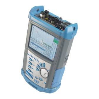
Introducing the FTB-200 Compact Modular Platform Main Features Your unit has the following characteristics: 2-slot platform Multitasking Touchscreen (LCD and touchscreen optimized for outdoor use available in option) USB ports (host and client) Ethernet port CompactFlash card reader Autonomy (8 hours) - Page 12 Introducing the FTB-200 Compact Modular Platform Main Features Front panel Touchscreen LEDs Keypad Knob with ENTER button Keypad Brightness button On/Off button Left panel Right panel Fiber Inspection Probe port Card reader RJ-45 port USB client port DC connector Headset/...
- Page 13 Introducing the FTB-200 Compact Modular Platform Main Features Top panel Built-in power meter Module slots Battery compartment Bottom panel Retaining screws Compact Modular Platform...
-
Page 14: Led Panel Description
Introducing the FTB-200 Compact Modular Platform LED Panel Description LED Panel Description The LED panel located on the front of the unit provides you with the status of your unit. Note: The function of certain LEDs vary with the applications. -
Page 15: Keypad Description
Introducing the FTB-200 Compact Modular Platform Keypad Description Keypad Description The keypad of your unit gives you access to various functions at all times. The table below shows an overview of their purpose. Note: The function of certain buttons vary with the applications. -
Page 16: Card Reader And Ports
Introducing the FTB-200 Compact Modular Platform Card Reader and Ports Card Reader and Ports Your unit is equipped with a card reader (for Bluetooth wireless and CompactFlash cards) and communication ports (for probe, mouse, keyboard, hub, etc.). The card reader is located on the left panel of the unit. -
Page 17: Power Sources
Introducing the FTB-200 Compact Modular Platform Power Sources Power Sources The unit operates with the following power sources: AC adapter/charger (connected to a standard power outlet–indoor use only). Rechargeable Lithium-Ion battery (automatically takes over if you disconnect the AC adapter/charger). -
Page 18: Conventions
Introducing the FTB-200 Compact Modular Platform Conventions Conventions Before using the product described in this manual, you should understand the following conventions: ARNING Indicates a potentially hazardous situation which, if not avoided, could result in death or serious injury. Do not proceed unless you understand and meet the required conditions. -
Page 19: Safety Information
Safety Information ARNING Do not install or terminate fibers while a light source is active. Never look directly into a live fiber and ensure that your eyes are protected at all times. ARNING Use of controls, adjustments and procedures for operation and maintenance other than those specified herein may result in hazardous radiation exposure or impair the protection provided by this unit. -
Page 20: Units With Built-In Vfl
If VFL option is available IEC 60825-1:1993+A2:2001 21 CFR 1040.10 LASER RADIATION AVOID DIRECT EYE EXPOSURE CLASS 3R LASER PRODUCT λ: 650 ±10 nm P out maximum < 5mW (into free space) Affixed to back of unit (under the stand). FTB-200... -
Page 21: Electrical Safety Information
Safety Information Electrical Safety Information Electrical Safety Information If you need to ensure that the unit is completely turned off, disconnect the power cable and remove the batteries. ARNING the external power supply indoors only. Position the unit so that the air can circulate freely around it. Operation of any electrical instrument around flammable gases or fumes constitutes a major safety hazard. - Page 22 Measured in 0 °C to 31 °C (32 °F to 87.8 °F) range, decreasing linearly to 50 % at 40 °C (104 °F). Not exceeding ± 10 % of the nominal voltage. The following label is affixed to the unit: Located on unit’s right panel FTB-200...
-
Page 23: Getting Started With Your Unit
CD (includes ActiveSync installation kit) a computer equipped with a USB port; Windows must be installed on the computer an FTB-200 unit a USB cable Note: For more information on the installation, refer to the Release Notes on the installation CD. - Page 24 (type B end). ActiveSync automatically opens and establishes the connection. 5. From the computer, on the Windows taskbar, click the Start button, then click Programs > EXFO > Handheld Instrument Software Manager. 6. Use Add Programs to install new versions. Follow the on-screen instructions.
-
Page 25: Inserting And Removing Test Modules
Inserting and Removing Test Modules Inserting and Removing Test Modules AUTION Never insert or remove a module while the FTB-200 Compact Modular Platform is turned on. This will result in immediate and irreparable damage to both the module and unit. - Page 26 Getting Started with Your Unit Inserting and Removing Test Modules To insert a module into the FTB-200 Compact Modular Platform: 1. Turn off your unit. 2. Position the unit so that its front panel is facing you. FTB-200...
- Page 27 Getting Started with Your Unit Inserting and Removing Test Modules 3. Take the module and place it vertically so that the retaining screw hole is at the left of the connector pins. AUTION Inserting a module upside down could result in permanent damage to the module, as the connector pins might be bent.
- Page 28 7. While applying slight pressure to the module, use a coin to turn the retaining screw clockwise until it is tightened. This will secure the module into its “seated” position. Turn retaining screws clockwise Bottom panel When you turn on the unit, the startup sequence will automatically detect the module. FTB-200...
- Page 29 Getting Started with Your Unit Inserting and Removing Test Modules To remove a module from the FTB-200 Compact Modular Platform: 1. Turn off your unit. 2. Position the unit so that the bottom panel is facing you. 3. Using a coin, turn the retaining screw counterclockwise until it stops.
- Page 30 5. Hold the module by its sides or by the handle (NOT by the connector) and pull it out. AUTION Pulling out a module by a connector could seriously damage both the module and connector. Always pull out a module by its casing. 6. Cover empty slots with the supplied protective covers. FTB-200...
-
Page 31: Installing A Usb Keyboard Or Mouse
Getting Started with Your Unit Installing a USB Keyboard or Mouse Installing a USB Keyboard or Mouse When you are required to enter alphanumeric data, an on-screen keyboard will be displayed. However, you can also use a hardware keyboard. You can also add a mouse. To install a USB keyboard or mouse on your unit: Connect the keyboard or the mouse to the type A USB port, located on the right side of the unit. -
Page 32: Configuring The Printer
Device Properties. 3. From Bluetooth Manager, press Scan Device to launch printer detection. Wait a few seconds until items appear in the Untrusted list. 4. From the Untrusted list, select the first Printek M2 item and press the -> button. FTB-200... - Page 33 Getting Started with Your Unit Configuring the Printer 5. When Bluetooth Manager prompts you to authenticate the device, answer No. MPORTANT If you answer Yes, the application will not be able to use the printer. 6. Once the item is on the Trusted list, select it. Press Active. A red check mark appears at the side of the icon to confirm the activation.
-
Page 34: Turning On Or Off The Unit
Hold down the On/Off button a few seconds until the unit beeps once. To perform a shutdown: Hold down the On/Off button a few seconds until the unit beeps twice. To turn on the unit: Press the On/Off button. FTB-200... -
Page 35: Starting Module Applications
Getting Started with Your Unit Starting Module Applications Starting Module Applications Your modules can be configured and controlled from their dedicated applications in Toolbox CE. To start a module application: 1. From Toolbox CE select the module to use. It will turn blue to indicate that it is highlighted. Selected module Modules inserted in the platform... -
Page 36: Accessing Microsoft Internet Explorer
3. Modify the settings using the information given to you by your network administrator. 4. Press OK to return to the Control Panel window. To access Internet Explorer: 1. From Toolbox CE, select the Programs tab. 2. Select the corresponding icon to access the browser. FTB-200... -
Page 37: Setting Up Your Unit
Setting Up Your Unit Recalibrating the Touchscreen If you notice the touchscreen does not behave in the way it used to (for example, it is now difficult to select items) it probably needs a recalibration. To recalibrate the touchscreen: 1. From the Main Menu, press Setup, then select Stylus. 2. -
Page 38: Adjusting Microphone And Speaker
To adjust microphone and/or speaker: 1. From the Main Menu, press Setup, then select Microphone and Speaker. 2. Use the slider to adjust the sound of your microphone and/or speaker. 3. Press OK to return to the Control Panel window. FTB-200... -
Page 39: Adjusting Brightness
Setting Up Your Unit Adjusting Brightness Adjusting Brightness To fit your work environment, you may adjust the LCD brightness. Values are kept in memory when you turn the unit off. Note: These settings do not apply to a fiber inspection probe display. To adjust the display brightness: Press the key repeatedly to switch between brightness levels. -
Page 40: Selecting The Language Of Operation
2. Press OK to return to the Control Panel window. Once you have modified the User interface language, you will be prompted to restart your unit. Note: Modifying the language of operation will affect the Windows CE language setting and vice versa. FTB-200... -
Page 41: Setting Date And Time Formats
Setting Up Your Unit Setting Date and Time Formats Setting Date and Time Formats The current date and time are displayed at the bottom of the Main Menu. When saving results, the unit also saves the corresponding date and time. Note: A dedicated clock battery keeps the date and time accurate. -
Page 42: Selecting The Startup Application
Note: The startup application you select will also be used after a power failure. If the specified application cannot be started (for example, in the FTB-200, the required module is not present in the unit or is not inserted in the same slot), the startup application setting is automatically reset to None. - Page 43 Setting Up Your Unit Selecting the Startup Application To select a startup application: 1. From the Main Menu, press Setup, then select Application Startup. 2. Under Device power on, select the application or applications you want to start automatically when you turn on your unit. Note: The Power Meter application is only available if you purchased this option with your unit.
-
Page 44: Configuring The Shortcut Buttons
2. Under Shortcut buttons, associate the application to each button. 3. Press Apply to confirm your changes, then OK to return to the Control Panel window. Setting Other Parameters You can also configure other parameters via the Control Panel window, refer to Microsoft Windows CE documentation. FTB-200... -
Page 45: Using The Built-In Power Meter And Vfl
Using the Built-In Power Meter and VFL The FTB-200 Compact Modular Platform can be equipped with an optical power meter to measure absolute power (dBm or W) or insertion loss (dB). The power meter can detect modulated signals (1 kHz, 2 kHz, and 270 Hz). - Page 46 Below is a description of the Power Meter buttons and functions. Reference value (when in reference mode) Selected wavelength Detected power Switches between available power meter wavelengths Switches between dBm and W as measurement units Accesses reference mode Stores a reading to the Results window FTB-200...
-
Page 47: Nulling Offsets
Using the Built-In Power Meter and VFL Nulling Offsets Nulling Offsets Temperature and humidity variations affect the performance of electronic circuits and optical detectors, which can offset measurement results. To compensate for this offset, the unit is equipped with an offset nulling function. -
Page 48: Setting Thresholds And Correction Factors
Correction factor for each Thresholds list (dB, dBm, W) wavelength for each wavelength Wavelength list When selected, green LED: pass/ red LED: fail To revert to default values FTB-200... - Page 49 Using the Built-In Power Meter and VFL Setting Thresholds and Correction Factors 3. Press Edit and modify thresholds for the selected wavelength. For the watt (W) threshold, select the desired order of magnitude. 4. Select the Show Pass/Fail Status with LED check box to activate the pass/fail LED on your unit.
-
Page 50: Setting Reference Values On Your Power Meter
3. From the Power Meter tab, use the up/down arrows to select a wavelength. Activate the source at the same wavelength. Wavelength list 4. Press Reference to save the current power value as the new reference. It will appear on the right-hand corner of the data display. FTB-200... -
Page 51: Measuring Power Or Loss
Using the Built-In Power Meter and VFL Measuring Power or Loss Measuring Power or Loss Measuring absolute power or link loss is done the same way, except for the referencing step. You can take power or loss measurements and save them for further analysis. - Page 52 9. Once the analysis is complete, press Quick Save. You can also access the Save File dialog box in the Storage window. MPORTANT If you specify a name that already exists, the original file will be overwritten and only the new file will be available. FTB-200...
- Page 53 Using the Built-In Power Meter and VFL Measuring Power or Loss To view and edit power measurements: 1. From the Power Meter tab, press Results. All your measurements are displayed in the order they were performed. 2. Press Rename to rename the fiber or press Delete to remove the selected value from the list.
-
Page 54: Reloading Power Meter Results
Then, you will be able to reload a new file afterwards. 4. To view the reloaded file, press Exit Storage. Then, from the Power Meter tab, press Results. The power measurements are displayed on the results list. FTB-200... -
Page 55: Clearing Power Measurements From The Display
Using the Built-In Power Meter and VFL Clearing Power Measurements from the Display Clearing Power Measurements from the Display If a measurement does not meet your requirements, you can clear the display and start over. Note: Clearing measurements from the display does not delete them from the disk (if they were saved previously). -
Page 56: Creating And Printing A Results Report
To speed up information entry, once you have provided the required data, you may keep the contents as a template that will be used for all new results. You can print two types of report: Type of report Summarized Detailed Cable information Job information Result table Average table Comments FTB-200... - Page 57 Using the Built-In Power Meter and VFL Creating and Printing a Results Report To create a power meter result report: 1. From the Power Meter tab, press Report. 2. Enter the relevant information. To erase all information You can save the information as a template by pressing Save as Template.
- Page 58 1. Connect a printer to your Compact Modular Platform. For more information, see Configuring the Printer on page 22. 2. From Power Meter tab, press Print. 3. Select the report format. 4. Press Print. You will automatically return to the Power Meter tab. FTB-200...
-
Page 59: Identifying Fiber Faults Visually With The Vfl
Using the Built-In Power Meter and VFL Identifying Fiber Faults Visually with the VFL Identifying Fiber Faults Visually with the VFL The visual fault locator (VFL) helps you identify bends, faulty connectors, splices and other causes of signal loss. It can also help the person at the other end of the link to identify the fiber under test, which could be particularly useful when working with cables containing many fibers. - Page 60 (CW) signals 6. Without looking directly into the beam, examine the fiber. If light is coming out of the rubber jacket or on the side of the ferrule, the fiber is defective. 7. Press ON/OFF to deactivate the VFL. FTB-200...
-
Page 61: Inspecting Fibers With A Probe
The following common features of fiber inspection probes are supported by the FTB-200 Compact Modular Platform: Magnification control: supports 200x, 400x or other zoom factors. Focus control: fine-tunes the display quality. - Page 62 3. Connect the fiber end or the connector to the probe. 4. Press Live Video. To adjust brightness To adjust contrast 5. Adjust brightness and contrast by using the sliders. 6. Adjust the focus by using the focus control knob on your probe. FTB-200...
-
Page 63: Capturing An Image
Inspecting Fibers with a Probe Capturing an Image Capturing an Image While you are inspecting a fiber, you can capture an image and save it on your unit as a JPEG or BMP file. You can transfer image files to a computer and add them to your reports. - Page 64 2. Open the folder in which your captures are saved. Default folder Selected capture Capture format 3. Double click on the capture you want to view. 4. Return to Live Video mode by pressing Main Menu. Repeat steps 1 to 3 to view other captures. FTB-200...
-
Page 65: Managing Data
USB secondary port (type B connector) to transfer data directly between your unit and a computer using a USB cable. MPORTANT To avoid any problems and prevent malfunctioning, use only the USB drives approved by EXFO Electro-Optical Engineering Inc. Compact Modular Platform... - Page 66 1. From Main Menu, press System Info. 2. Select Platform. The free disk space is displayed next to Available Flash items. 3. When you have finished, close System Information. To manage files or folders on your unit only: From Main Menu, select File Manager. FTB-200...
- Page 67 Managing Data To transfer files or folders between your unit and a CompactFlash card or a USB memory drive: Note: Ensure that the CompactFlash card holes for the connector pins are towards the back of the card reader and that you see the label with a small arrow on top.
- Page 68 1. If it is not already done, install Microsoft ActiveSync. 2. Connect the USB cable to the computer (type A end) and your unit (type B end). Note: The computer and your unit do not need to be off when you connect the cable. FTB-200...
- Page 69 Managing Data 3. Once ActiveSync indicates that the computer and your unit are connected, right-click the ActiveSync icon then select Explore to access the files and folders stored on your unit. On the computer desktop, double-click My Computer, then Mobile Device to access the files and folders stored on your unit.
-
Page 71: Testing Network Connections
Testing Network Connections The two most common basic tests widely used in networking are the ping test and the trace route test. With these tests, you can ensure that IP packets travel as expected from a local host to a remote host and vice versa. - Page 72 Testing Network Connections Performing a Ping Test To perform a ping test: 1. From Toolbox CE, select the Programs tab, then select IP Testing Tools. 2. From IP Testing Tools, select the Ping tab. FTB-200...
- Page 73 Testing Network Connections Performing a Ping Test 3. Enter an URL or an IP address to reach. You can press the Default button to use the unit's default ping address. The default value cannot be configured. 4. Set the parameters: Packet size Number of packets to send Timeout limit...
-
Page 74: Performing A Trace Route Test
Set the maximum number of hops allowed for reaching the remote host (TTL). Choose whether to resolve DNS for the IP address or not. When the test is complete, you can export the results. You can later import the generated text file (tab-delimited) directly into Microsoft Excel. FTB-200... - Page 75 Testing Network Connections Performing a Trace Route Test To perform a Trace Route test: 1. From IP Testing Tools, select the Trace Route tab. 2. Enter an URL or an IP address to reach. You can press the Default button to use the unit's default trace route address. The default value cannot be configured.
-
Page 76: Exporting The Results
[DAY] is the day of the test. Example: For a ping test at www.yoursite.org made on January 3 , 2006, the suggested filename would be: Ping for www.yoursite.org on 2006_01_03.txt To export results: Press the Export button. If necessary, modify the suggested file name. FTB-200... -
Page 77: Maintenance
Maintenance To help ensure long, trouble-free operation: Always inspect fiber-optic connectors before using them and clean them if necessary. Keep the unit free of dust. Clean the unit casing and front panel with a cloth slightly dampened with water. Store unit at room temperature in a clean and dry area. Keep the unit out of direct sunlight. -
Page 78: Cleaning Detector Ports
4. While applying light pressure (to avoid breaking the detector window), gently rotate the cleaning tip on the detector window. 5. Repeat step 4 with a dry cleaning tip or blow dry with compressed air. 6. Discard the cleaning tips after one use. FTB-200... -
Page 79: Recharging The Main Battery
Maintenance Recharging the Main Battery Recharging the Main Battery The main Lithium-Ion battery will last about 8 hours in normal operation. The clock battery is recharged automatically along with the main battery. In Toolbox CE, the charge status is shown above Main Menu. The unit also indicates the charge status with LED on its front panel (see LED Panel Description on page 4): Status LED... - Page 80 A complete calibration cycle will be necessary (see Recalibrating the Battery on page 71). To recharge the main battery: Connect the unit to a power outlet using the AC adapter/charger. The charge cycle will start and end automatically. FTB-200...
-
Page 81: Recalibrating The Battery
Maintenance Recalibrating the Battery Recalibrating the Battery Depending on the way the unit is used, after a while, the charge status icon may no longer correspond to the actual power level of the battery (for example , icon indicates that power level is sufficient, but unit turns off because battery is too weak). - Page 82 Maintenance Recalibrating the Battery To recalibrate the batteries: 1. From the Main Menu, select Setup, and then Battery Calibration. FTB-200...
- Page 83 Maintenance Recalibrating the Battery 2. Connect the AC adapter/charger to your unit. 3. Press the Start Calibration button (the Stop Calibration button will become available). Once calibration is complete, the Start Calibration button becomes available again. Compact Modular Platform...
-
Page 84: Replacing Batteries
Do not throw batteries into fire or water and do not short-circuit the battery’s electrical contacts. Do not disassemble. To replace the main battery: 1. If you do not have a replacement battery, contact EXFO to purchase a new one. 2. Turn off the unit. -
Page 85: Recalibrating The Unit
You should determine the adequate calibration interval for your unit according to your accuracy requirements. Under normal use, EXFO recommends calibrating your unit every year. Compact Modular Platform... -
Page 86: Recycling And Disposal (Applies To European Union Only)
This equipment was sold after August 13, 2005 (as identified by the black rectangle). Unless otherwise noted in a separate agreement between EXFO and a customer, distributor, or commercial partner, EXFO will cover costs related to the collection, treatment, recovery, and disposal of... -
Page 87: 10 Troubleshooting
10 Troubleshooting Solving Common Problems Problem Cause Solution Unit does not turn on. Battery is discharged. Charge the battery. Replace the battery with a fully charged one. Connect the unit to an external power supply using the AC adapter/charger. Unit is not connected Connect the unit to an external power to an external power supply using the AC adapter/charger. - Page 88 Your unit is not Restore your unit. To do so, see responding. Restoring Your Unit to Normal Operation section. A complete battery calibration cycle consists of a full charge, immediately followed by a full discharge, then followed by a full charge. FTB-200...
-
Page 89: Restoring Your Unit To Normal Operation
Restoring Your Unit to Normal Operation Restoring Your Unit to Normal Operation If you ever encounter major problems with your FTB-200 Compact Modular Platform (for example, you cannot start your unit) you can restore your unit to normal operation from the maintenance mode. For current updates, use the Handheld Instrument Software Manager (HISM). - Page 90 Your unit may restart several times during the installation. If the operation was successful, you can now use your unit. If your unit still does not work properly, try restoring the system partition from a USB memory drive or a CompactFlash card. FTB-200...
- Page 91 HISM. Your unit will restart several times. This operation takes 5 to 7 minutes to complete and is done when Toolbox CE is displayed. If your unit still does not work properly, contact EXFO’s technical support group. Compact Modular Platform...
-
Page 92: Contacting The Technical Support Group
Contacting the Technical Support Group To obtain after-sales service or technical support for this product, contact EXFO at one of the following numbers. The Technical Support Group is available to take your calls from Monday to Friday, 8:00 a.m. to 7:00 p.m. -
Page 93: Transportation
Troubleshooting Transportation Transportation Maintain a temperature range within specifications when transporting the unit. Transportation damage can occur from improper handling. The following steps are recommended to minimize the possibility of damage: Pack the unit in its original packing material when shipping. Avoid high humidity or large temperature fluctuations. -
Page 95: 11 Warranty
EXFO Electro-Optical Engineering Inc. (EXFO) warrants this equipment against defects in material and workmanship for a period of one year from the date of original shipment. EXFO also warrants that this equipment will meet applicable specifications under normal use. During the warranty period, EXFO will, at its discretion, repair, replace,... -
Page 96: Liability
Liability Liability EXFO shall not be liable for damages resulting from the use of the product, nor shall be responsible for any failure in the performance of other items to which the product is connected or the operation of any system of which the product may be a part. -
Page 97: Exclusions
Warranty Exclusions Exclusions EXFO reserves the right to make changes in the design or construction of any of its products at any time without incurring obligation to make any changes whatsoever on units purchased. Accessories, including but not limited to fuses, pilot lamps, batteries and universal interfaces (EUI) used with EXFO products are not covered by this warranty. -
Page 98: Service And Repairs
5. Return the equipment, prepaid, to the address given to you by support personnel. Be sure to write the RMA number on the shipping slip. EXFO will refuse and return any package that does not bear an RMA number. -
Page 99: Exfo Service Centers Worldwide
Warranty EXFO Service Centers Worldwide EXFO Service Centers Worldwide If your product requires servicing, contact your nearest authorized service center. EXFO Headquarters Service Center 400 Godin Avenue 1 866 683-0155 (USA and Canada) Quebec (Quebec) G1M 2K2 Tel.: 1 418 683-5498... - Page 101 MPORTANT The following technical specifications can change without notice. The information presented in this section is provided as a reference only. To obtain this product’s most recent technical specifications, visit the EXFO Web site at www.exfo.com. SPECIFICATIONS SPECIFICATIONS Display FTB-85102...
- Page 102 FP1 200X Fiber Inspection Probe GP-2017 Spare FTB-200 battery FP5 400X Fiber Inspection Probe GP-2019 USB micro drive standard capacity GP-10-072 Semi-rigid FTB-200 carrying case GP-2021 Spare AC charger (requires AC external adapter/charger). GP-302 USB mouse (A-E-I-J-S-U) Specify: A–North America, E–Europe, I–India, J–Japanese,...
- Page 103 75 fiber, measuring optical power....41 interval ..........75 front panel, cleaning ........67 Canadian Standards Association (CSA) ..viii FTB-200 shutting down ....... 24 cancelling dark current effects ....37 capacitors............ 11 car outlet, charging battery with....70 caution hard drive LED ..........
- Page 104 LED............. 4 power meter safety accessing ..........35 caution ............ 8 buttons description ....... 36 conventions ..........8 creating a report........46 information..........9 measurement......... 41 warning ........... 8 printing a report ........48 service and repairs ........88 FTB-200...
- Page 105 ..........89 setting warm shutdown .......... 24 power thresholds (power meter) ... 38 warranty reference values........40 certification..........87 shipping to EXFO ........88 exclusions ..........87 shutdown general........... 85 cold vs. warm ........24 liability ........... 86 FTB-200 ..........24 null and void..........
- Page 106 CHINESE REGULATION ON RESTRICTION OF HAZARDOUS SUBSTANCES NAMES AND CONTENTS OF THE TOXIC OR HAZARDOUS SUBSTANCES OR ELEMENTS CONTAINED IN THIS EXFO PRODUCT Indicates that this toxic or hazardous substance contained in all of the homogeneous materials for this part is below the limit requirement in SJ/T11363-2006...
- Page 107 MARKING REQUIREMENTS Product Environmental protection use period (years) Logo This Exfo product EXFO Battery If applicable.
- Page 108 Beijing New Century Hotel Office Tower, Beijing 100044 P. R. CHINA Room 1754-1755, No. 6 Southern Capital Tel.: +86 (10) 6849 2738 · Fax: +86 (10) 6849 2662 Gym Road © 2009 EXFO Electro-Optical Engineering Inc. All rights reserved. Printed in Canada (2009-08)
Need help?
Do you have a question about the FTB-200 and is the answer not in the manual?
Questions and answers