Table of Contents
Advertisement
Quick Links
Advertisement
Table of Contents

Related Manuals for EXFO CT440 Series


Summary of Contents for EXFO CT440 Series
- Page 1 User Guide CT440 Passive Optical Component Tester www.EXFO.com...
-
Page 2: Copyright
Information provided by EXFO is believed to be accurate and reliable. However, no responsibility is assumed by EXFO for its use nor for any infringements of patents or other rights of third parties that may result from its use. No license is granted by implication or otherwise under any patent rights of EXFO. -
Page 3: Table Of Contents
Contents Contents Copyright ................................ii Contents ................................iii Regulatory Information ............................v 1 Introducing the CT440 ......................1 Product Features ..............................1 Technical Specifications ............................7 Product Overview ..............................9 Conventions ...............................11 Abbreviations Used ............................12 2 Safety Information ......................13 Other Safety Symbols on Your Unit ........................14 Optical Safety Information ..........................14 Electrical Safety Information ..........................15 3 Getting Started with Your CT440 ..................17... -
Page 4: Contents
11 Warranty ..........................93 General Information ............................93 Liability ................................93 Exclusions ................................94 Certification ...............................94 Service and Repairs ............................95 EXFO Service Centers Worldwide ........................96 A Description of Functions ....................97 Data Types .................................97 Initialization Functions ............................98 Configuration Functions ..........................100 Measurement Control Functions ........................117 Data Handling Functions ..........................122... -
Page 5: Regulatory Information
Electronic test and measurement equipment is exempt from FCC part 15, subpart B compliance in the United States of America and from ICES-003 compliance in Canada. However, EXFO Inc. makes reasonable efforts to ensure compliance to the applicable standards. The limits set by these standards are designed to provide reasonable protection against harmful interference when the equipment is operated in a commercial environment. -
Page 7: Introducing The Ct440
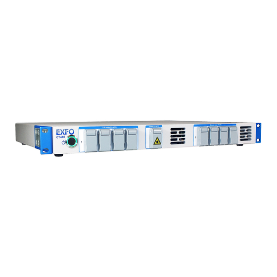
Introducing the CT440 Product Features The CT440 is a compact instrument designed for spectral characterization of passive optical components by synchronous optical power detection using one or more sweeping laser source(s). It covers the specified transmission band in one run. The CT440 provides the transmission function (TF) of the device under test (DUT) with the help of one or more sweeping laser sources. - Page 8 The CT440 is provided with a control software (GUI) that you can install on a computer. Earlier versions of CT440 EXFO has modified the external design of the CT440. The following figure displays the previous models of CT440 and CT440-PDL.
- Page 9 Introducing the CT440 Product Features Measurement Principle Input and Output TLS Input(s) The TLS input(s) of the CT440 includes an interferometric system generating a detection trigger, which provides high wavelength accuracy and removes the need for electrical triggering of the instrument. The free-spectral range (FSR) of this interferometric system is about 100 MHz, which translates, into the wavelength domain, to a spacing of 0.55 pm at 1260 nm and 0.75 pm at 1550 nm.
- Page 10 Introducing the CT440 Product Features Polarization State Generator (only on CT440 with PDL option) On CT440 with PDL option, the signal passes through a polarization state generator (PSG) that produces one of 6 states of polarization at the output port. Data Acquisition: Raw and Resampled Data The interferometric system triggers data acquisition every 100 MHz.
- Page 11 Introducing the CT440 Product Features Detection System One to four optical detectors enable the CT440 to provide the direct TF and PDL (if available) of the DUT with up to four outputs. The additional electrical input port (Analog In BNC at the rear of the instrument) can ...
- Page 12 Introducing the CT440 Product Features Scan span > 5 nm The scan span is important for the absolute and relative accuracy. The largest span leads to the most accurate results (the specifications are for a 100 nm span). Below 5 nm, the precision cannot be guaranteed and a warning message is issued to prevent such running condition.
-
Page 13: Technical Specifications
MPORTANT The following technical specifications can change without notice. The information presented in this section is provided as a reference only. To obtain this product’s most recent technical specifications, visit the EXFO Web site at www.exfo.com. Measurement Specifications PM13 PM15... - Page 14 Introducing the CT440 Technical Specifications Interfaces & Electrical Specifications PM13 PM15 PDL-O PDL-SCL Optical Ports TLS inputs & Number of input 1 to 4 1 (PM13) 1 (PM15) 1 (PM13) 1 (PM15) outputs ports Number of output 1 (PM13) 1 (PM15) 1 (SMF) ports Connector type...
-
Page 15: Product Overview
Introducing the CT440 Product Overview Product Overview The CT440 is made of two complementary parts: The CT440 instrument, which makes measurements during the wavelength scan The CT440 software (GUI), which takes the data from the instrument and performs all ... - Page 16 Introducing the CT440 Product Overview Rear Panel Cooling fans Labels Fuse holder Power cord Analog In USB-B 2.0 connector port Digital In Power switch connectors Digital Out Cooling Fans The cooling fans extract warm air from inside. A cover grid protects them. Fuse Holder The fuse holder contains two fuses (see Technical Specifications on page 7 for fuse type) to protect the CT440 from overcurrent.
-
Page 17: Conventions
Introducing the CT440 Conventions Labels Label Description Identification of the product (left side): serial number, model, options (if any), hardware version and manufacturing date. Information on the product (right side): power requirements, manufacturer information and compliances. The fuse type is described in Technical Specifications on page 7. -
Page 18: Abbreviations Used
Introducing the CT440 Abbreviations Used Abbreviations Used Abbreviation Meaning Dynamic Link Library Digital Signal Processor Device Under Test Free-spectral range GPIB General Purpose Interface Bus Graphical User Interface Insertion Loss Polarization Dependent Loss Polarization Extinction Ratio Polarization Dependent Loss Polarization State Generator Transfer Function Tunable Laser Source Transistor-Transistor Logic... -
Page 19: Safety Information
If the equipment is used in a manner not specified by the manufacturer, the protection provided by the equipment may be impaired. ARNING Use only accessories designed for your unit and approved by EXFO. For a complete list of accessories available for your unit, refer to its technical specifications or contact EXFO. -
Page 20: Other Safety Symbols On Your Unit
Safety Information Other Safety Symbols on Your Unit Other Safety Symbols on Your Unit One or more of the following symbols may also appear on your unit. Symbol Meaning Direct current Alternating current The unit is equipped with an earth (ground) terminal. The unit is equipped with a protective conductor terminal. -
Page 21: Electrical Safety Information
Safety Information Electrical Safety Information Electrical Safety Information This unit uses an international safety standard three-wire power cable. This cable serves as a ground when connected to an appropriate AC power outlet. ARNING If you need to ensure that the unit is completely turned off, disconnect the ... - Page 22 Safety Information Electrical Safety Information AUTION Position the unit so that the air can circulate freely around it. Equipment Ratings Temperature Operation +15 °C to +35 °C (+59 °F to +95 °F) Storage -10 °C to +60 °C (+14 °F to +140 °F) Relative humidity <...
-
Page 23: Getting Started With Your Ct440
MPORTANT When unpacking, handle the device with care and do not damage the original shipping container in case the CT440 needs to be returned to EXFO. 2. Set the CT440 on a flat stable surface free of excessive vibration. 3. Do one of the following: To use the CT440 as a bench-top instrument, set it on a flat stable surface free of ... -
Page 24: Installing The Ct440 In A Rack
Getting Started with Your CT440 Installing the CT440 in a Rack Installing the CT440 in a Rack To be able to install the CT440 in a rack, you must first install the rack-mounting brackets on each side of the instrument. The brackets are delivered with eight screws (8 mm) to fasten it on each side panels of the instrument with a Phillips head screwdriver. -
Page 25: Connecting The Ct440 To A Power Source
Getting Started with Your CT440 Connecting the CT440 to a Power Source To install the CT440 in a 19-inch rack: 1. Make sure that: You have a 1U space in your rack You have four rack mounting screws and cage nuts (no rack fastening kit is ... -
Page 26: Setting Up Your Computer
7. 1b. Make sure you have writing permission on the folder in which the CT440 software will be installed (the default folder is C:\Program Files (x86)\EXFO). 2. Do one of the following: Connect the CT440 USB key to the USB-A port of your computer. -
Page 27: Starting/Stopping The Ct440
Getting Started with Your CT440 Starting/Stopping the CT440 To update the CT440 software: The last version of the CT440 software is available on the EXFO website. Updating the CT440 software does not affect the existing traces, configuration, nor selected analysis parameters. - Page 28 To start the CT440 GUI software Click the shortcut icon located on your desktop or into Start\All Programs\EXFO\CT440 If the CT440 is detected, the GUI appears, all parameters are set as you left them before the last GUI stop. For more details on the interface, see Understanding the User Interface on page 22.
- Page 29 Getting Started with Your CT440 Starting/Stopping the CT440 Scan Parameters Area This area displays the scan parameters selected in the Scan Parameters window. For more details, see Configuring Scan Parameters on page 35. Graph Display Settings The buttons located in this area enable you to adapt the graph display to your needs. For more details, see Adjusting the Graph Display on page 53.
-
Page 31: Setting Up Your Ct440 For Measurements
Setting Up Your CT440 for Measurements This section details how to setup connections of the CT440 in a standard use. For more information on how to use the trigger, measurement synchronization and external detector, see sections Setting up a Triggered Scan on page 42, Synchronizing the CT440 with External Measurements on page 44 and Performing a Measurement Using the Analog In BNC Connector on page 47. - Page 32 Setting Up Your CT440 for Measurements Connecting the Tunable Laser(s) (GPIB Use) Before starting: Make sure you have the following material: One or more tunable laser(s). A GPIB card or GPIB controller (if the CT440 is used in trigger mode, this adapter is not ...
-
Page 33: Performing User Referencing
Setting Up Your CT440 for Measurements Performing User Referencing Performing User Referencing Zeroing the Electrical Offset on Detectors The zeroing function enables you to mitigate the effect of dark current on low power level measurement by first measuring the power on the selected detector when no fiber is connected and then storing that value for power correction. - Page 34 When using the CT440 GUI for the first time, the factory calibration file is created and stored on the control computer, in the appropriate Calib folder: C:\Users\Public\Documents\EXFO\CT440\Calib The file name is <serial number>.bin. Performing a user referencing updates this file.
- Page 35 Setting Up Your CT440 for Measurements Performing User Referencing To perform power referencing: 1. To obtain the optimum performance of the system, make sure the optical connectors are perfectly clean (see Cleaning Optical Connectors on page 80). 2. Connect a verified optical jumper between the output port of the CT440 and the detector port you want to reference.
- Page 36 Setting Up Your CT440 for Measurements Performing User Referencing Performing Wavelength Referencing The CT440 should not encounter any shift in its wavelength accuracy between factory calibrations. The Wavelength Referencing area of the Referencing window enables you to improve the accuracy of the wavelength referencing if needed by adding an offset to the factory calibration.
- Page 37 Setting Up Your CT440 for Measurements Performing User Referencing 5. In the Referencing window, in the Wavelength Referencing area: 5a. In the Measurement (nm) field, enter the measured value. 5b. In the Reference (nm) field, enter the expected value for this absorption line (in nm).
-
Page 38: Connecting The Dut To The Ct440
Setting Up Your CT440 for Measurements Connecting the DUT to the CT440 Connecting the DUT to the CT440 This section explains how to connect the device under test to the CT440 in a standard use. For more information on how to use the external detector, see Performing a Measurement Using the Analog In BNC Connector on page 47. - Page 39 Setting Up Your CT440 for Measurements Connecting the DUT to the CT440 To connect the DUT to the CT440: 1. Connect the input (or common) port of the DUT to the CT440 Output port. ARNING Depending on the safety class of the laser(s) you have connected to the CT440 input port(s), the beam coming from the CT440 output port may be dangerous.
-
Page 40: Verifying The Power And Voltage Levels
Setting Up Your CT440 for Measurements Verifying the Power and Voltage Levels Verifying the Power and Voltage Levels In the Referencing window, the power control bars only provides an indication of the power, allowing you to adjust the magnitude of the inputs/outputs of your setup before launching scan measurements. -
Page 41: Performing Measurement Scans
Performing Measurement Scans Configuring the CT440 for Measurements Before starting a measurement, you must configure the TLS and detectors used, and the wanted scan and measurement parameters. Configuring Scan Parameters The Scan Parameters window enables you to select and configure the appropriate laser type(s) connected to your CT440 and to set the scan parameters. - Page 42 Performing Measurement Scans Configuring the CT440 for Measurements Parameter Description PDL Method CT440 with PDL option only. 4 States: the CT440 performs 4 polarization-controlled successive sweeps to achieve the PDL measurement. 6 States: the CT440 performs 6 polarization-controlled successive sweeps to achieve the PDL measurement. This provides the best measurement performance but it takes longer.
- Page 43 Performing Measurement Scans Configuring the CT440 for Measurements 3. Set the wanted scanning options according to the instructions given in the following table. Parameter Description Mode Scanning mode of the CT440: Single The CT440 performs a scan of the wavelength range set in the Start/Stop fields and then stops.
- Page 44 Performing Measurement Scans Configuring the CT440 for Measurements To configure the laser settings: 1. Start the CT440 (see Starting/Stopping the CT440 on page 21). 2. In the main window, click the button located to the left of the Scan button. The Scan Parameters window appears.
- Page 45 Performing Measurement Scans Configuring the CT440 for Measurements Configuring Trace Parameters The CT440 can displays 8 traces. Each trace is represented by a different color. The Trace x Parameters window allows you to configure the type of measurement you want the CT440 to perform for each trace. You cannot set trace parameters during a scan.
- Page 46 Performing Measurement Scans Configuring the CT440 for Measurements Parameter Description Type Live: the trace pictures the next scan. Store: the trace is frozen. It won't be modified by next scans. Hold Min: the trace pictures the minimum scanned values point ...
-
Page 47: Manually Starting/Stopping A Scan
Performing Measurement Scans Manually Starting/Stopping a Scan Manually Starting/Stopping a Scan Once you have set all the appropriate parameters, you can start scanning as explained in the following procedure. Before starting: 1. Configure the scan parameters so that they correspond to your setup (see Configuring Scan Parameters on page 35). -
Page 48: Setting Up A Triggered Scan
Performing Measurement Scans Setting up a Triggered Scan Setting up a Triggered Scan You can control the CT440 measurement with a trigger signal by using the Trigger In BNC connector, as explained in this section. The following figure illustrates the hardware setup for a triggered scan: no GPIB controller is required, but a BNC cable. - Page 49 Performing Measurement Scans Setting up a Triggered Scan To set up a triggered scan: 1. Using a BNC 50 Ω coaxial cable, connect the Trigger out port (providing the TTL signal) of the laser to the input digital Trigger In BNC connector located on the rear panel of the CT440 (see Rear Panel on page 10).
-
Page 50: Synchronizing The Ct440 With External Measurements
Performing Measurement Scans Synchronizing the CT440 with External Measurements Synchronizing the CT440 with External Measurements If additional detectors are required for any reason, you can use the synchronization signal (TTL) provided at the Trigger Out BNC connector of the CT440 to perform simultaneous measurements on remote platforms. - Page 51 Performing Measurement Scans Synchronizing the CT440 with External Measurements The following figure illustrates the hardware setup for external TF measurements with a CT440 SMF. CT440 Pulses During the scan of the laser, the CT440 generates TTL pulses at the Trigger Out BNC connector.
- Page 52 Performing Measurement Scans Synchronizing the CT440 with External Measurements To synchronize the CT440 with external measurements: 1. Using the coaxial cable, connect the Trigger In port of the remote instrument receiving the TTL signal to the Trigger Out BNC connector located on the rear panel of the CT440 (see Rear Panel on page 10).
-
Page 53: Performing A Measurement Using The Analog In Bnc Connector
Performing Measurement Scans Performing a Measurement Using the Analog In BNC Connector Performing a Measurement Using the Analog In BNC Connector The CT440 enables you to measure an electric signal through the Analog In BNC input port during the scan. You can measure the voltage of the electric signal or the optical power of the signal. - Page 54 Performing Measurement Scans Performing a Measurement Using the Analog In BNC Connector To measure the voltage of the electric signal: 1. In the Referencing window, in the Analog In BNC area, select Voltage in the Measurement list. MPORTANT This operation clears all traces related to an active TF or PDL measurement on Analog In BNC.
- Page 55 Performing Measurement Scans Performing a Measurement Using the Analog In BNC Connector To measure the optical power of the signal: 1. In the Referencing window, in the Analog In BNC area: 1a. In the Measurement list, select Optical Power. The P fields become available. MPORTANT This operation clears all traces related to an active voltage measurement on Analog In BNC.
-
Page 56: Performing Line Wavelength Measurements
Performing Measurement Scans Performing Line Wavelength Measurements Performing Line Wavelength Measurements Line wavelength measurement is only available for CT440 SMF models with two or more TLS inputs. CT440 featuring two or more TLS inputs include a powerful heterodyne detection system: it detects precisely when the source of an input port crosses the wavelength of the source connected to the next input. - Page 57 Performing Measurement Scans Performing Line Wavelength Measurements To perform line wavelength measurements: 1. Connect a TLS to input port 1 and a laser source to input port 2 with an overlapped wavelength. 2. Start a measurement (see Manually Starting/Stopping a Scan on page 41). All spectral lines present in the source are detected in one scan and displayed in the Line detection tab, as illustrated in the following example window.
-
Page 58: Saving/Loading Configuration Parameters
All the associated traces (in a separate folder). The default location of the CT440 configuration folder is: C:\Users\Public\Documents\EXFO\CT440\Config To save your configuration parameters: 1. In the main window, click the Save button. 2. In the Explorer window: Select Configuration Files (.conf). -
Page 59: Displaying And Operating Scan Traces On Graph
Displaying and Operating Scan Traces on Graph The graph area tab displays the scan results measured by the CT440 and enables you to manage scans and traces. The left scale in dB applies to the transfer function measurement. The right scale depends on the trace displayed on graph: ... -
Page 60: Changing The Spectral Unit On Graph
Displaying and Operating Scan Traces on Graph Changing the Spectral Unit on Graph Changing the Spectral Unit on Graph You can switch the x-axis unit of the graph to THz or nm by using the unit button located in the configuration area. To modify the spectral unit: To set the graph spectral unit to THz, click the nm button so that is displays THz. - Page 61 Displaying and Operating Scan Traces on Graph Performing Measurements with Markers To perform measurements with markers: 1. Activate the trace on which you want to position markers by clicking on its label. The trace button is circled anda colored flag appears on the corner of the activation button to indicate that the trace is brought to front and activated.
-
Page 62: Handling Traces
Displaying and Operating Scan Traces on Graph Handling Traces Handling Traces Displaying/Hiding/Activating Traces By default all traces are displayed on graph, each one has a different color. The trace button displays the trace measurement and type. It is circled with a colored flag on the corner if the trace is activated. -
Page 63: Analyzing Traces
Analyzing Traces The Analysis Parameters window provides analysis tools specific to the characterization of pass band filters, stop band filters and isolators. For each trace displayed on graph, a set of analysis tools adapted to the tested component is available, according to the appropriate detection threshold. Defining the Analysis Parameters The Analysis Parameters window displays all parameters of the analysis you can perform on traces. - Page 64 Analyzing Traces Defining the Analysis Parameters Parameter Description Component Type of component to test (corresponding to the selected Analyzed Trace). The selection of a component makes available the analysis tools adapted to the selected component. Component Pass Band Stop Band Isolator Filter Filter...
- Page 65 Analyzing Traces Defining the Analysis Parameters Defining Spectral Width Analysis Parameters The Spectral Width 1, Spectral Width 2 and Spectral Width 3 analysis tools are available for Pass Band Filter component analysis. They allow you to identify in a spectral trace the width of the main peak at three given thresholds below the peak power and the central wavelength.
- Page 66 Analyzing Traces Defining the Analysis Parameters Spectral Width Detection Settings Algorithm: method used for the calculation of the width. Threshold (default) The Threshold algorithm detects the wavelengths and at which the power falls below [Peak Power]-[Width Threshold]. To account for the multimodal nature of some sources, several options are available for this algorithm (see Fitting Options below), illustrated in the following figure.
- Page 67 Analyzing Traces Defining the Analysis Parameters RMS/RMS Peak The RMS and RMS Peak algorithms calculate the root mean square value of the power data above a given Width Threshold, taking the full power data (RMS) or simply the Power at Peak (RMS Peak) for the calculation. Width Threshold Wavelength or Frequency Gaussian Fit/Lorentzian Fit...
- Page 68 Analyzing Traces Defining the Analysis Parameters Width Threshold Threshold level used in the calculation of the width. It defines two wavelengths - and + with Power P = P – Width Threshold. peak Default values: - Spectral Width 1 tab: 3 dB - Spectral Width 2 tab: 5 dB - Spectral Width 3 tab: 20 dB Mode Threshold (only for Envelope, Gaussian Fit and Lorentzian Fit algorithms).
- Page 69 Analyzing Traces Defining the Analysis Parameters Defining Notch Width Analysis Parameters The Notch Width 1, Notch Width 2 and Notch Width 3 tools are available for the stop band filter and isolator components analysis. They allow you to identify in a spectral trace the width of a trough at a given threshold above the trough power.
- Page 70 Analyzing Traces Defining the Analysis Parameters Notch Selection Options Notch Selection: method used for the selection of the trough to analyze. Deepest Notch: selection of the feature with biggest difference between trough and adjacent peaks. Minimum Trough (default): selection of the lowest level trough. ...
- Page 71 Analyzing Traces Defining the Analysis Parameters Defining Pass Band Test Analysis Parameters The Pass Band Test tool is available for the pass band filter component analysis. It allow you to get cross-talk, average loss, ripple and roll-off characteristics for a pass band filter. Before starting: Make sure you have defined the general analysis parameters (see Defining the Analysis Parameters on page 57).
- Page 72 Analyzing Traces Defining the Analysis Parameters CrossTalk Settings Reference Reference point taken for the analysis of the characteristics of the filter: Peak WL (default): peak wavelength found in the Spectral Width 1 tool results (see Spectral Width x Results on page 75). Center WL: center wavelength found in the Spectral Width 1 tool results (see ...
- Page 73 Analyzing Traces Defining the Analysis Parameters IN/OUT Band Distance (only if In/Out Band Method is set to Set Distance) Spectral spacing in nm/THz between the in-band reference point and the out-band reference points to be used for the crosstalk calculation. Default value: 1 nm Average Loss &...
- Page 74 Analyzing Traces Defining the Analysis Parameters PT Detection: detects all peaks and troughs within the Bandwidth 1 using Detection Threshold, The span is then set as the distance between the first and last peak detected for a pass band filter. Slope Ripple IN Bandwidth 1...
- Page 75 Analyzing Traces Defining the Analysis Parameters Roll-Off & Transition Band Settings Transition Reference Reference point to be used in the transition calculation: In-Band (default): the transition band is defined as the part of the trace between Level@ Transition Reference - Min Exclusion Threshold and Level@ Transition Reference - Max Exclusion Threshold.
- Page 76 Analyzing Traces Defining the Analysis Parameters Defining Stop Band Test Analysis Parameters The Stop Band Test tool is available for the stop band filter component analysis. It allow you to get isolation depth, average loss, ripple and roll-off characteristics for a pass band filter.
- Page 77 Analyzing Traces Defining the Analysis Parameters Isolation Depth Settings Reference Reference point taken for the analysis of the characteristics of the filter: Trough WL (default): peak wavelength found in the Notch Width 1 tool results (see Notch Width x Results on page 75). Center WL: center wavelength found in the Notch Width 1 tool results (see Notch ...
- Page 78 Analyzing Traces Defining the Analysis Parameters IN/OUT Band Distance (only if In/Out Band Method is set to Set Distance) Spectral spacing in nm/THz between the in-band reference point and the out-band reference points to be used for the isolation depth calculation. Default value: 1 nm Average Loss &...
- Page 79 Analyzing Traces Defining the Analysis Parameters PT Detection: detects all peaks and troughs within the Bandwidth 1 using Detection Threshold, The span is then set as the distance between the first and last trough detected for a stop band filter. OUT Ref OUT Ref Avg Loss OUT...
- Page 80 Analyzing Traces Defining the Analysis Parameters Roll-Off & Transition Band Settings Transition Reference Reference point to be used in the transition calculation: In-Band (default): the transition band is defined as the part of the trace between Level@ Transition Reference - Min Exclusion Thresh. and Level@ Transition Reference - Max Exclusion Thresh.
-
Page 81: Displaying And Understanding The Analysis Results
Analyzing Traces Displaying and Understanding the Analysis Results Displaying and Understanding the Analysis Results In the main window, the Analysis Results tab under the graph provides the results of the analysis. Before starting: Make sure you have configured the analysis parameters according to your needs as explained in Defining the Analysis Parameters on page 57. - Page 82 Analyzing Traces Displaying and Understanding the Analysis Results Pass Band Test Results In-Band Results Result Meaning Average Loss Average loss in dB measured across Averaging Range around the in-band reference point. Uniformity in dB as the min/max level difference measured within Ripple Averaging Range around the In-Band reference point.
- Page 83 Analyzing Traces Displaying and Understanding the Analysis Results Stop Band Test Results In-Band Results Result Meaning Average Loss Average loss in dB measured across Averaging Range around the in-band reference point. Uniformity in dB as the min/max level difference measured within Ripple Averaging Range around the In-Band reference point.
-
Page 84: Saving Analysis Results
Analyzing Traces Saving Analysis Results Saving Analysis Results The following procedure explains how to save the analysis results of the CT440 in a .csv file. The file contains the analysis parameters and the corresponding results. To save analysis results: 1. In the main window, click the Save button. 2. -
Page 85: Maintenance
ARNING To avoid personal injury, never remove the protective cover of the chassis to perform servicing or maintenance operations. You must refer to your EXFO service representative. CT440... -
Page 86: Cleaning Optical Connectors
Maintenance Cleaning Optical Connectors Cleaning Optical Connectors To ensure measurement accuracy and prevent loss of optical power, you must verify that optical connectors are clean every time you connect a fiber. Handle optical fiber with appropriate care and preserve the integrity of optical connectors by keeping them free of contamination. -
Page 87: Replacing Fuses
Maintenance Replacing Fuses Replacing Fuses You must verify the power fuses in case you cannot turn on the CT440. ARNING To avoid fire hazard, only use the correct fuse type, voltage and current ratings. The unit contains two fuses (see Technical Specifications on page 3 for details). The fuse holder is located at the back of the unit, at the right of the power inlet. -
Page 88: Cleaning The Ct440
Under normal conditions of use, we recommend to perform a factory recalibration of the CT440 after one year of normal use. To ask for a factory recalibration: Contact the EXFO customer support service (see Contacting the Technical Support Group on page 89) Recycling and Disposal... -
Page 89: Troubleshooting
TLS is too Scan speed too low Make sure the reference file is located in low (< 8nm/s) the proper Calib folder: The reference file is not C:\Users\Public\Documents\EXFO\CT440\ located in the correct Calib folder. CT440... - Page 90 Make sure the reference file is located in Scan speed too high high (> 120nm/s). the proper Calib folder: The reference file is not C:\Users\Public\Documents\EXFO\CT440\ located in the correct Calib folder. Make sure the reference file is located in...
- Page 91 located in the correct Make sure the reference file is located in folder or is corrupted. the proper Calib folder: C:\Users\Public\Documents\EXFO\CT440\ Calib Make sure the reference file is located in the proper Calib folder: C:\Users\Public\Documents\EXFO\CT440\ Calib Reset the reference file as follows: ...
- Page 92 [error code 2] A failure occurred during Check the USB connection. the communication Contact the EXFO customer support Failure in data exchange between the computer and with the DSP service (see Contacting the Technical the internal DSP .
- Page 93 CT440, so that the wavelength ranges follow the port order. [error code 4] Hardware failure on the Contact the EXFO customer support service optical switch. (see Contacting the Technical Support Group Switch failure on page 89).
-
Page 94: Activating The Usb Driver
CT440 USB Device and select Update driver. You are prompted to select the appropriate driver. 3. To select the USB driver, browse your computer and select the following location: C:\Program Files (x86)\EXFO\CT440\USB Driver The CT440 can now communicate with your computer. CT440... -
Page 95: Contacting The Technical Support Group
Contacting the Technical Support Group Contacting the Technical Support Group To obtain after-sales service or technical support for this product, contact EXFO at one of the following numbers. The Technical Support Group is available to take your calls from Monday to Friday, 8:00 a.m. to 7:00 p.m. (Eastern Time in North America). -
Page 97: Installing/Updating The Ct440 Library
10 Installing/Updating the CT440 Library This section explains how to install the CT440 library on your computer, and update it from a preceding version to the new one. All features of the CT440 DLL are described in Description of Functions on page 97. The CT440 DLL applies to all models of CT440. - Page 98 Software Package on Your Computer on page 20. The CT440 library is installed in the following folder: C:\Program Files (x86)\EXFO\CT440\Library x.xx 2. Start the GUI software and make sure you can operate the CT440 and laser through the graphical user interface.
-
Page 99: 11 Warranty
General Information EXFO Inc. (EXFO) warrants this equipment against defects in material and workmanship for a period of 1 from the date of original shipment. EXFO also warrants that this equipment will meet applicable specifications under normal use. During the warranty period, EXFO will, at its discretion, repair, replace, or issue credit for any defective product, as well as verify and adjust the product free of charge should the equipment need to be repaired or if the original calibration is erroneous. -
Page 100: Exclusions
Exclusions Exclusions EXFO reserves the right to make changes in the design or construction of any of its products at any time without incurring obligation to make any changes whatsoever on units purchased. Accessories, including but not limited to fuses, pilot lamps, batteries and universal interfaces (EUI) used with EXFO products are not covered by this warranty. -
Page 101: Service And Repairs
5. Return the equipment, prepaid, to the address given to you by support personnel. Be sure to write the RMA number on the shipping slip. EXFO will refuse and return any package that does not bear an RMA number. -
Page 102: Exfo Service Centers Worldwide
Fax: +86 (755) 2955 3101 Xintian Avenue, support.asia@exfo.com Fuhai, Bao’An District, Shenzhen, China, 518103 To view EXFO's network of partner-operated Certified Service Centers nearest you, please consult EXFO's corporate website for the complete list of service partners: http://www.exfo.com/support/services/instrument-services/ exfo-service-centers. CT440... -
Page 103: A Description Of Functions
Description of Functions This section describes all functions of the CT440 Library. Data Types The following table describes all specific data types defined for the CT440 library. Data Type Description and Possible Values Type of laser: rLaserSource LS_TunicsPlus LS_TunicsPurity ... -
Page 104: Initialization Functions
Description of Functions Initialization Functions Initialization Functions CT440_Init Applicability All models of CT440. Description This function initializes the DLL for connection to a CT440 and returns a handle. If the DSP version of the CT440 is not compatible with the DLL in use, a pop-up window prompts you to automatically upgrade the DSP firmware. - Page 105 Description of Functions Initialization Functions CT440_CheckConnected Applicability All models of CT440. Description This function verifies if the CT440 is connected to the computer. Declaration int32_t CT440_CheckConnected(uint64_t uiHandle); Parameter uiHandle Handle returned from CT440_Init Type: Input Data type: unsigned int64 Return value 1: a CT440 is connected.
-
Page 106: Configuration Functions
Description of Functions Configuration Functions Configuration Functions CT440_SetLaser Applicability All models of CT440. Description This function configures the parameters of the laser connected to the CT440. In the GUI, this function corresponds to the Laser Settings area in the Scan Parameters window. Declaration int32_t CT440_SetLaser(uint64_t uiHandle, rLaserInput eLaser,... - Page 107 Description of Functions Configuration Functions CT440_SetLaser Parameters iGPIBInterfaceID GPIB interface ID of laser GPIB controller. Refer to your GPIB controller firmware setup to set the correct ID number. Possible values: 0 to 100 Type: Input Data type: int32 iGPIBAdress GPIB address of the laser. Possible values: 1 to 30 Type: Input Data type: int32...
- Page 108 Description of Functions Configuration Functions CT440_CmdLaser Applicability All models of CT440. Description This function enables you to control a laser connected to the computer via GPIB. It sets the wavelength, power and state (enable/disable). Declaration int32_t CT440_CmdLaser(uint64_t uiHandle, rLaserInput eLaser, rEnable eEnable, double dWavelength, double dPower);...
- Page 109 Description of Functions Configuration Functions CT440_SwitchInput Applicability CT440 models with twoor more TLS input ports. Description This function selects the CT440 input port, which enables the use of the laser connected to this port. Declaration int32_t CT440_SwitchInput(uint64_t uiHandle, rLaserInput eLaser); Parameters uiHandle Handle returned from CT440_Init...
- Page 110 Description of Functions Configuration Functions CT440_SetScan Applicability All models of CT440. Description This function sets the scan parameters. In the GUI, this function corresponds to the Scanning Range settings in the Scan Parameters window. Declaration int32_t CT440_SetScan(uint64_t uiHandle, double dLaserPower, double dMinWavelength, double dMaxWavelength, uint32_t * uiResolution);...
- Page 111 Description of Functions Configuration Functions CT440_SetScan Return value 0: the operation succeeded. -1: the operation failed. Data type: int32 Example uint32_t *uiResolution = 0; uiResolution = (uint32_t *) calloc(1, sizeof(uint32_t)); *uiResolution = 5; CT440_SetScan(uiHandle, 1.0, 1500.0, 1600.0, uiResolution); free(uiResolution);...
- Page 112 Description of Functions Configuration Functions CT440_SetDetectorArray Parameters uiHandle Handle returned from CT440_Init Type: Input Data type: unsigned int64 eDect2 Enables/Disables the detector 2. Possible values: see Data Types on page 97. Type: Input Data type: rEnable eDect3 Enables/Disables the detector 3. Possible values: see Data Types on page 97.
- Page 113 Description of Functions Configuration Functions CT440_PolState Applicability CT440 with PDL option only. Description This function sets the state of polarization of the polarization state generator in the CT440 with PDL option. For 4-states method PDL measurement, you must provide the states 0;...
- Page 114 Description of Functions Configuration Functions CT440_SetBNC Applicability All models of CT440. On CT440 with PDL option, PDL measurement is not guaranteed if you use the BNC C interface. Description This function configures the CT440 BNC analog port labeled C (located on the rear panel of the instrument) during the scan. This function enables you to get the measured voltage converted in dBm or mW, according to the entered parameters.
- Page 115 Description of Functions Configuration Functions CT440_SetBNC dBetadAlpha Optical power (offset) Beta parameter in mW or dBm (P = dBeta + dAlpha x V) Possible values: depend on the external power meter or detector used. Type: Input Data type: double eUnit Units: Possible values: Possible values: see Data Types on page 97.
- Page 116 Description of Functions Configuration Functions CT440_SetExternalSynchronization Applicability All models of CT440. On CT440 with PDL option, you cannot use this function to perform a direct PDL measurement. PDL measurements use resampled data, not raw data. Description This function configures the CT440 external synchronization output (Trigger OutBNC connector located on the rear panel of the instrument).
- Page 117 Description of Functions Configuration Functions CT440_SetExternalSynchronizationIN Applicability All models of CT440. Description This function configures the CT440 to run a scan triggered by the connected tunable laser (Trigger In BNC connector located on the rear panel of the instrument). For more details, see Setting up a Triggered Scan on page 42. In the GUI, this function corresponds to the Single Trig or Continuous Trig scanning modes in the Scan Parameters window.
- Page 118 Description of Functions Configuration Functions CT440_UpdateWavelengthReference Applicability All models of CT440. Description This function modifies the reference wavelength by adding an offset to the factory wavelength calibration. In the GUI, this function corresponds to the Wavelength Referencing area in the Referencing window. Declaration int32_t CT440_UpdateWavelengthReference(uint64_t uiHandle, double RefWavelength,...
- Page 119 Description of Functions Configuration Functions CT440_MeasureDark Applicability All models of CT440. Description This function measures the power on the selected detector and stores it for power correction. The measured power is automatically taken into account for correction in the next power measurement. In the GUI, this function is identical to the Zero Detector X buttons in the Referencing window.
- Page 120 Description of Functions Configuration Functions CT440_ResetDark Applicability All models of CT440. Description This function removes the detector dark current correction. Declaration int32_t CT440_ResetDark (uint64_t uiHandle, rDetector eDetector); Parameters uiHandle Handle returned from CT440_Init Type: Input Data type: unsigned int64 eDetector Front panel detector number.
- Page 121 Description of Functions Configuration Functions CT440_ResetCalibration Applicability All models of CT440. Description This function resets to default all referencing modifications done on the wavelength referencing and on detector referencing. In the GUI, this function is identical to the Reset Calibration button in the Referencing window.
- Page 122 Description of Functions Configuration Functions CT440_UpdateCalibration (Deprecated) Applicability CT440 without PDL option only, for legacy compatibility with CT400. Description This function references a single CT440 detector. It must be called after a scan has been performed on the same detector. Before sending the command, connect the CT440 output port directly to the selected detector with an SMF jumper.
-
Page 123: Measurement Control Functions
Description of Functions Measurement Control Functions Measurement Control Functions CT440_ScanStart Applicability All models of CT440. Description This function starts a scan. On CT440 with PDL option, one scan is performed at only one polarization state. For PDL measurement, you need to combine this function with the CT440_PolState function (page 107) to record all 4 or 6 states of polarization and be able to measure the PDL. - Page 124 Description of Functions Measurement Control Functions CT440_ScanAbort Applicability All models of CT440. Description This function aborts a scan. In the GUI, this function corresponds to the Abort button when a start has been started. Declaration int32_t CT440_ScanAbort(uint64_t uiHandle); Parameter uiHandle Handle returned from CT440_Init Type: Input Data type: unsigned int64...
- Page 125 Description of Functions Measurement Control Functions CT440_ScanWaitEnd Applicability All models of CT440. Description This function waits for the scan to finish and returns errors or warnings. The list of these messages is available in Troubleshooting on page 83. Declaration int32_t CT440_ScanWaitEnd (uint64_t uiHandle,char tcError[1024]);...
- Page 126 Description of Functions Measurement Control Functions CT440_ScanGetProgress Applicability All models of CT440. Description This function returns the completion state of the scan in progress. Declaration int32_t CT440_ScanGetProgress(uint64_t uiHandle, rLaserInput * activeLaser, int32_t * allLasersProgress, int32_t * activeLaserProgress, int32_t * status, char tcError[1024]);...
- Page 127 Description of Functions Measurement Control Functions CT440_ScanGetProgress tcError[1024] Initialized array that stores the description of the error. Type: Input/Output Data type: char|1024] Return value 0: the operation succeeded. -1: the operation failed. Data type: int32 Example rLaserInput * activeLaser = (rLaserInput *) calloc(1, sizeof(rLaserInput));...
-
Page 128: Data Handling Functions
Description of Functions Data Handling Functions Data Handling Functions CT440_ScanGetWavelengthSyncArray Applicability All models of CT440. On CT440 with PDL option, you cannot use this function to directly calculate PDL; you must use the CT440_ScanGetWavelengthResampledArray on page 124. Description This function performs the following: Gets the total number of measured wavelength points. - Page 129 Description of Functions Data Handling Functions CT440_ScanGetWavelengthSyncArray Return value > 0: indicates the available number of data points in dArray and the corresponding data values. -1: the operation failed. Data type: int32 Example int32_t iArraySize = CT440_GetNbDataPoints(uiHandle); double *dWavelengthSync=(double*)calloc(iArraySize,sizeof(double));...
- Page 130 Description of Functions Data Handling Functions CT440_ScanGetWavelengthResampledArray Applicability All models of CT440. Description This function performs the following: Gets the total number of wavelength points produced by the CT440, spaced by the uiResolution parameter (see CT440_SetScan on page 104). The step between points corresponds to the resolution set in CT440_SetScan on page 104.
- Page 131 Description of Functions Data Handling Functions CT440_ScanGetWavelengthResampledArray Return value > 0: indicates the available number of (resampled) data points in dArray and the corresponding data values. -1: the operation failed. Data type: int32 Example int32_t iArraySize = CT440_GetNbDataPointsResampled(uiHandle); double *dWavelength=(double*)calloc(iArraySize,sizeof(double));...
- Page 132 Description of Functions Data Handling Functions CT440_ScanGetPowerSyncArray Applicability All models of CT440. On CT440 with PDL option, you cannot use this function to directly calculate PDL; you must use CT440_ScanGetPowerResampledArray on page 128. Description This function performs the following: Gets the total number of output power values (measured at the ...
- Page 133 Description of Functions Data Handling Functions CT440_ScanGetPowerSyncArray Return value > 0: indicates the available number of measured points in dArray and the corresponding data values. -1: the operation failed. Data type: int32 Example int32_t iArraySize = CT440_GetNbDataPoints(uiHandle); double *dPowerSync=(double*)calloc(iArraySize,sizeof(double)); ScanGetPowerSyncArray(uiHandle,dPowerSync,iArraySize);...
- Page 134 Description of Functions Data Handling Functions CT440_ScanGetPowerResampledArray Applicability All models of CT440. Description This function performs the following: Gets the total number of output power values (measured at the output port of the CT440) associated with the wavelength values produced by the CT440.
- Page 135 Description of Functions Data Handling Functions CT440_ScanGetPowerResampledArray Return value > 0: indicates the available number of measured points in dArray and the corresponding data values. -1: the operation failed. Data type: int32 Example int32_t iArraySize = CT440_GetNbDataPointsResampled(uiHandle); double *dPowerSync=(double*)calloc(iArraySize,sizeof(double)); ScanGetPowerResampledArray(uiHandle,dPowerSync,iArraySize);...
- Page 136 Description of Functions Data Handling Functions CT440_ScanGetDetectorArray Applicability All models of CT440. On CT440 with PDL option, you cannot use this function to directly calculate PDL; you must use CT440_ScanGetDetectorResampledArray on page 133. Description This function performs the following: Gets the total number of measured transfer function points on a ...
- Page 137 Description of Functions Data Handling Functions CT440_ScanGetDetectorArray Parameters uiHandle Handle returned from CT440_Init Type: Input Data type: unsigned int64 eDetector Detector number. Possible values: see Data Types on page 97. Type: Input Data type: rDetector dArray Pointer over an initialized array to return all the measured transfer function values.
- Page 138 Description of Functions Data Handling Functions CT440_ScanGetDetectorArray Return value > 0: indicates the available number of measured points in dArray and the corresponding data values. -1: the operation failed. Data type: int32 If the eDetector parameter is set to DE_5 and the CT440_SetBNC on page 108 is set to DISABLE, the value returned by the CT440_ScanGetDetectorArray function is the voltage measured at the Analog In BNC port.
- Page 139 Description of Functions Data Handling Functions CT440_ScanGetDetectorResampledArray Applicability All models of CT440. Description This function performs the following: Returns the points corresponding to the transfer function (or to one state of PDL) on a selected detector associated with the wavelength points produced by the CT440.
- Page 140 Description of Functions Data Handling Functions CT440_ScanGetDetectorResampledArray Parameters uiHandle Handle returned from CT440_Init Type: Input Data type: unsigned int64 eDetector Detector number. Possible values: see Data Types on page 97. Type: Input Data type: rDetector dArray Pointer over an initialized array to return all the re-sampled measured transfer function values.
- Page 141 Description of Functions Data Handling Functions CT440_ScanGetDetectorResampledArray Return value > 0: indicates the available number of measured points in dArray and the corresponding data values. -1: the operation failed. Data type: int32 If the eDetector parameter is set to DE_5 and the CT440_SetBNC on page 108 is set to DISABLE, the value returned by the CT440_ScanGetDetectorResampledArray function is the voltage measured at the Analog In BNC port.
- Page 142 Description of Functions Data Handling Functions CT440_ScanSaveWavelengthSyncFile Applicability All models of CT440. On CT440 with PDL option, you cannot use this function to directly calculate PDL; you must use the CT440_ScanSaveWavelengthResampledFile on page 137. Description This function saves the wavelength points measured by the CT440 in a text file.
- Page 143 Description of Functions Data Handling Functions CT440_ScanSaveWavelengthResampledFile Applicability All models of CT440. Description This function saves in a text file the wavelength values measured by the CT440 spaced by the uiResolution parameter (see CT440_SetScan on page 104). The step between values corresponds to the resolution set in CT440_SetScan on page 104.
- Page 144 Description of Functions Data Handling Functions CT440_ScanSavePowerSyncFile Applicability All models of CT440. On CT440 with PDL option, you cannot use this function to directly calculate PDL; you must use the CT440_ScanSavePowerResampledFile on page 139. Description This function saves in a text file the output power and transfer function values measured on the enabled detector(s) associated with the recorded pulse number.
- Page 145 Description of Functions Data Handling Functions CT440_ScanSavePowerResampledFile Applicability All models of CT440. Description This function saves in a text file the output power associated with the wavelength values measured by the CT440, spaced by the uiResolution parameter (see CT440_SetScan on page 104). The step between points corresponds to the resolution set in CT440_SetScan on page 104).
- Page 146 Description of Functions Data Handling Functions CT440_ScanSaveDetectorFile Applicability All models of CT440. On CT440 with PDL option, you cannot use this function to directly calculate PDL; you must use CT440_ScanSaveDetectorResampledFile on page 141 function. Description This function saves in a text file the transfer function values measured by the CT440 on a selected detector associated with the recorded pulse number.
- Page 147 Description of Functions Data Handling Functions CT440_ScanSaveDetectorResampledFile Applicability All models of CT440. Description This function saves in a text file the transfer function (or one state of PDL) values on a selected detector associated with the wavelength values measured by the CT440 spaced by the uiResolution parameter (see CT440_SetScan on page 104).
- Page 148 Description of Functions Data Handling Functions CT440_ReadPowerDetectors Applicability All models of CT440. Description This function reads the instantaneous optical power (in dB) measured at the Output port and on the four detectors, and reads the voltage (in V) on the Analog In BNC port. In the GUI, this function corresponds to the Power Monitoring and Voltage Monitoring areas the Referencing window.
- Page 149 Description of Functions Data Handling Functions CT440_ReadPowerDetectors Pointer over an initialized variable to store the power measured on detector 3 (in dB). Type: Input/Output Data type: double* Pointer over an initialized variable to store the power measured on detector 4 (in dB). Type: Input/Output Data type: double* Vext...
- Page 150 Description of Functions Data Handling Functions CT440_GetNbDataPoints Applicability All models of CT440. On CT440 with PDL option, you cannot use this function to directly calculate PDL; you must use CT440_GetNbDataPointsResampled on page 146. Description This function returns: The number of measured data points after a scan has been ...
- Page 151 Description of Functions Data Handling Functions CT440_GetNbDataPoints Parameters uiHandle Handle returned from CT440_Init Type: Input Data type: unsigned int64 iDataPoints Pointer to a variable that stores the number of valid data points measured by the CT440. Type: Input/Output Data type: unsigned int32 iDiscardPoints Pointer to a variable that stores the index of the trigger pulse associated with the first measured data point.
- Page 152 Description of Functions Data Handling Functions CT440_GetNbDataPointsResampled Applicability All models of CT440. Description This function returns the number of valid (re-sampled) data points after a scan has been performed. Declaration int32_t CT440_GetNbDataPointsResampled (uint64_t uiHandle); Parameter uiHandle Handle returned from CT440_Init Type: Input Data type: unsigned int64 Return value...
- Page 153 Description of Functions Data Handling Functions CT440_CalcPDL4OneDET Applicability CT440 with PDL option only. Description Calculate IL and PDL on one detector. You must provide Ref, WL and DET data for each polarization state in the correct order. Declaration int32_t CT440_CalcPDL4OneDET(uint64_t uiHandle, int32_t iMethod, int32_t iNbvalues, double * dWLwithoutDUT,...
- Page 154 Description of Functions Data Handling Functions CT440_CalcPDL4OneDET dWLwithoutDUT Pointer over an array containing the wavelength for each state during the measurement without DUT. Type: Input Data type: double* dRefwithoutDUT Pointer over an array containing the reference power for each state during the measurement without DUT.
- Page 155 Description of Functions Data Handling Functions CT440_CalcPDL4OneDET dPDL Pointer over an array containing the calculated PDL for each data points. Type: Input/Output Data type: double* iTabsize Pointer over an initialized variable to store the size of dIL, dPDL and dWLadjusted arrays. Type: Input/Output Data type: int32* Return value...
- Page 156 Description of Functions Data Handling Functions CT440_GetNbLinesDetected Applicability CT440 with two or more input ports only. Description This function returns the number of spectral lines detected with heterodyne detection. Declaration int32_t CT440_GetNbLinesDetected (uint64_t uiHandle); Parameter uiHandle Handle returned from CT440_Init Type: Input Data type: unsigned int64 Return value...
- Page 157 Description of Functions Data Handling Functions CT440_ScanGetLinesDetectionArray Applicability CT440 with two or more input ports only. Description This function returns the values of spectral lines detected by heterodyne detection. In the GUI, this function gets the results displayed in the Line detection tab.
-
Page 158: Instrument Information Functions
Description of Functions Instrument Information Functions Instrument Information Functions CT440_GetNbInputs Applicability All models of CT440. Description This function returns the number of available TLS inputs on the connected CT440 model. Declaration int32_t CT440_GetNbInputs(uint64_t uiHandle); Parameter uiHandle Handle returned from CT440_Init Type: Input Data type: unsigned int64 Return value... - Page 159 Description of Functions Instrument Information Functions CT440_GetCT440Type Applicability All models of CT440. Description This function returns the type of CT440 connected to your computer. Declaration int32_t CT440_GetCT440Type(uint64_t uiHandle); Parameter uiHandle Handle returned from CT440_Init Type: Input Data type: unsigned int64 Return value 0: the CT440 model type is SMF.
- Page 160 Description of Functions Instrument Information Functions CT440_GetCT440SN Applicability All models of CT440. Description This function returns the serial number of the CT440 connected to your computer. Declaration int32_t CT440_GetCT440SN(uint64_t uiHandle,char SN[50]); Parameters uiHandle Handle returned from CT440_Init Type: Input Data type: unsigned int64 SN[50] Allocated memory for storing the serial number.
- Page 161 Description of Functions Instrument Information Functions CT440_GetCT440DSPver Applicability All models of CT440. Description This function returns the DSP firmware version of the CT440 connected to your computer. Declaration int32_t CT440_CT440_GetCT440DSPver(uint64_t uiHandle, int32_t * iDSPversion); Parameters uiHandle Handle returned from CT440_Init Type: Input Data type: unsigned int64 iDSPversion...
-
Page 163: B Program Examples
Program Examples EXFO provides an example on how to use the CT440_lib.dll in C, Python and LabVIEW programming languages. An example is available for each platform (Win32 and Win64). CT440_testwrap.c/CT440-PDL_testwrap.c are examples of the DLL use in C language. ... - Page 164 Program Examples IL and/or PDL are calculated and depending on the language used: LabVIEW: results are displayed on graph and in a table. C and Python: results are saved in a .xls file in the current folder. 7. The communication between the CT440 and the computer is closed and the memory allocated by the dll is released.
-
Page 165: Index
Index Index CT440_PolState ............107 CT440_ReadPowerDetectors........142 CT440_Reset Dark ........... 114 CT440_ResetCalibration........... 115 CT440_ScanAbort............ 118 abbreviations ............12 CT440_ScanGetDetectorArray ......... 130 AC requirements ............16 CT440_ScanGetDetectorResampledArray ....133 after-sales service ............89 CT440_ScanGetLineDetectionArray ......151 analog in ............8, 10, 47 CT440_ScanGetPowerResampledArray .... - Page 166 ..............54 service centers ............96 maximum setup ................. 25 input current ............16 shipment ..............89 measurement principle..........3 shipping to EXFO ............95 measurements............35 software package ............... 20 update ..............21 specifications............... 7 notch width ............63, 75 specifications, product ..........
- Page 167 Index technical support ............89 temperature for storage..........79 connection............26 requirements ............5 trace activate..............56 display ..............56 hide ..............56 load ..............56 parameters ............39 save ..............56 transportation requirements ....... 79, 89 trigger in ............8, 10, 42 trigger out............
- Page 168 CHINESE REGULATION ON RESTRICTION OF HAZARDOUS SUBSTANCES (RoHS) 中国关于危害物质限制的规定 NAMES AND CONTENTS OF THE TOXIC OR HAZARDOUS SUBSTANCES OR ELEMENTS CONTAINED IN THIS EXFO PRODUCT 包含在本 EXFO 产品中的有毒有害物质或元素的名称及含量 Part Name Lead Mercury Cadmium Hexavalent Polybrominated Polybrominated Chromium biphenyls diphenyl ethers 部件名称...
- Page 169 · info@exfo.com CORPORATE HEADQUARTERS 400 Godin Avenue Quebec (Quebec) G1M 2K2 CANADA Tel.: 1 418 683-0211 · Fax: 1 418 683-2170 TOLL-FREE (USA and Canada) 1 800 663-3936 © 2019 EXFO Inc. All rights reserved. ...
Need help?
Do you have a question about the CT440 Series and is the answer not in the manual?
Questions and answers