Table of Contents
Advertisement
Quick Links
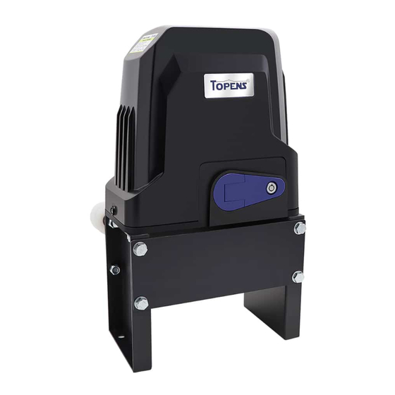
Belt Sliding Gate Opener
User's Manual
Model:
BK800
TOPENS Website
www.topens.com
Email: support@topens.com
★ Please read and follow all warnings, precautions and instructions before
installation and use.
★ Periodic checks of the opener are required to ensure safe operation.
★ Save this manual.
VER 23a
C030619
Advertisement
Table of Contents

Related Manuals for Topens BK800


Summary of Contents for Topens BK800
- Page 1 Belt Sliding Gate Opener User’s Manual Model: BK800 TOPENS Website www.topens.com Email: support@topens.com ★ Please read and follow all warnings, precautions and instructions before installation and use. ★ Periodic checks of the opener are required to ensure safe operation. ★ Save this manual.
- Page 2 Visit: www.topens.com Please record the product model, your email address etc. in the spaces provided below. Refer to this list when contacting TOPENS for technical service or assistance with your automatic gate opener. Where did you purchase? (Amazon.com; Amazon.ca: Amazon.co.uk, Amazon.de; Other, Please...
-
Page 3: Table Of Contents
Preparation for Installation ..........................2 Parts List ................................4 Accessories Parts (Included in some models, refers to the actual package) ..........4 Optional Accessories Parts List (Available at TOPENS Store) ................ 5 Replacement Parts ............................5 Technical Specifications & Features ........................ 6 Installation Overview ............................ -
Page 4: Check Your Gate Before Installation
Thank you for purchasing our sliding gate opener. We are sure that the products will be greatly satisfying as soon as you start to use it. The product is supplied with a user’s manual which encloses installation and safety precautions. These should be read carefully before installation and operation as they provide important information about safety, installation, operation and maintenance. -
Page 5: Preparation For Installation
danger caused by squashing, conveying and shearing. • Position at least one visible indication device, and fix a Warning sign to the structure. • The factory declines all responsibility with respect to the automation safety and correct operation when other supplier’s components are used. •... - Page 6 In sake of safety, a positive stop must be mounted on the two end of ground track.
-
Page 7: Parts List
Parts List Accessories Parts (Included in some models, refers to the actual package) -
Page 8: Optional Accessories Parts List (Available At Topens Store)
JD110VY / JD230VY AC TEW3 Vehicle Sensor Warning Light Exit Wand Replacement Parts ACPYMJ7C Control ACPYMJ8C Control PYMJ-CKG Limit Switch Board (120V) Board (230V) WARNING: Changes or modifications not expressly specified by this user manual, TOPENS could void the warranty of this equipment. -
Page 9: Technical Specifications & Features
Technical Specifications & Features Specifications Power input: 110~120V/60Hz or 220~240V/50Hz Motor voltage: 120VAC or 230VAC Rated power: 350W Gate moving speed: 20 cm/s (8 in/s) Max gate weight: 800kg (1800lbs) Max gate length: 12m(40ft) Environmental conditions: -20℃~ +50℃ (0° F to 120° F) Protection class: IP44 multiple safety protection (90 seconds) -
Page 10: Installation Of The Opener
Installation of the Opener Caution: *Be sure that the opener is installed in a level and paralleled position. Improper installation could result in property damage, severe injury, and/or death. * Before starting installation, ensure that there is no point of friction during the entire movement of the gate and there is no danger of derailment. -
Page 11: Installation Of Belt And Brackets
Installation of belt and brackets 1. Belt Brackets 1). Please refer to below brackets figure, which shows “U” bolt, “L” bracket and tension bolt. Use the “U” bolts (square or round) to attach the “L” brackets to gate frame. 2). If Both the square bolts and round bolts are not fit for the gate frame, use the appropriate bolts to attach the brackets to gate frame. - Page 12 6). The belt brackets must be mounted to the same height as the belt under the idler wheels. 7). Make sure there is 1” distance at least between the wheels and the gate after you position the base plate.
-
Page 13: Installation Of The Magnets
Installation of the Magnets Before install limit switch, make sure the gate opener is put in manual operation. (the clutch connected with gear shaft is disengaged) and the mains power supply is disconnected. Position the two Magnet Components approximately on the gate and move the gate by hand to fix them in place. Fit magnets bracket Push the gate fully closed by hand. -
Page 14: Connecting Of Power Supply
Connecting of Power Supply WARNING: NEVER connect the gate opener to the power outlet before all the installations have been done. The power supply cord should be at least 3×0.75mm (3C×18AWG). Connect the live wire and neutral wire to the “L” (1) and “N” (2) terminal of the control board respectively;... - Page 15 2. Limit Switches The YELLOW wire of the limit switches should be connected into the “8” terminal. The BLACK wire of the limit switches should be connected into the “9” terminal. The RED wire of the limit switches should be connected into the “10” terminal. 3.
-
Page 16: Setting Of The Control Board
The BLACK wire of the exit wand should be connected into the “15”terminal. The BLUE wire of the exit wand should be connected into the “16” terminal. The RED wire of the exit wand should be connected into the “11”terminal. The GREEN wire of the exit wand should be connected into the “13”... -
Page 17: Test The Reversing Sensitivity
Important Note: When the auto close function is enabled, the photocell sensor is highly recommended to be installed with the gate opener for safety. DIP Switch #4: Left/Right open 2. Potentiometers Potentiometer A and B are used to adjust the stall force and auto close time of the gate operator separately. Turn potentiometer A clockwise to increase the stall force, and turn it counter-clockwise to decrease the stall force. -
Page 18: How To Program Or Erase The Remote
All of TOPENS sliding gate opener have midway mode. Button B is designed to realize midway function (refer to more details in our TOPENS sliding gate opener manual). So it is must program button A with sliding gate opener, while you may program either C button or D button with TOPENS swing gate opener. -
Page 19: Wireless Keypad Programming
Wireless Keypad Programming You can follow the below steps to program wireless keypad to the opener. Press the LNSW button until the LEARN LED is ON, and then releases the button. Then press "OK" button on keypad and LEARN LED will flash for 3 seconds and then be OFF which indicates the keypad has been programmed successfully. - Page 20 6. Check the limit switch. Remove the wire connection of the limit switch which is connected to the 8#, 9#, and 10# terminals of the control board and then use a jumper wire to short the 3 terminals together to try it again. Replace the limit switch if the motor could run in both directions.
-
Page 21: Maintenance
Maintenance Every six months check the following items for proper operation of the unit. * Lubricate shafts and sprockets. * Keep operator clean at all times. * Check and tighten anchors bolts. * Check for loose or corroded wire * Ensure the operator is well earthed, and correctly terminated. * Always check the Stop/Reverse in case of obstruction function when performing any maintenance. - Page 22 Your comments and suggestions are important to us as they help us provide the best possible service. Should you have any need to contact us, the info below will help you get in touch: TOPENS Website www.topens.com Contact Us: E-mail: support@topens.com Kindly include your Product Model, Purchasing Date &...
Need help?
Do you have a question about the BK800 and is the answer not in the manual?
Questions and answers