Table of Contents
Advertisement
Quick Links
R8-14...R20-14
Model: EVO 20 RJ
Assembly and Operating Instructions
en
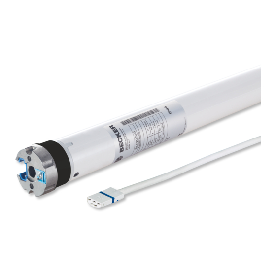
Tubular drive with variable output speed for roller
shutter systems with blind function
Important information for:
• Fitters / • Electricians / • Users
Please forward accordingly!
These instructions must be kept safe for future reference.
1010 300 011 0d 31/05/2022
Becker-Antriebe GmbH
Friedrich-Ebert-Straße 2-4
35764 Sinn/Germany
www.becker-antriebe.com
Advertisement
Table of Contents

Related Manuals for Becker EVO 20 RJ


Summary of Contents for Becker EVO 20 RJ
- Page 1 R8-14...R20-14 Model: EVO 20 RJ Assembly and Operating Instructions Tubular drive with variable output speed for roller shutter systems with blind function Important information for: • Fitters / • Electricians / • Users Please forward accordingly! These instructions must be kept safe for future reference.
-
Page 2: Table Of Contents
Table of contents General .................................... 3 Warranty ..................................... 3 Safety instructions ................................ 4 Instructions for the user.............................. 4 Instructions for installation and commissioning........................ 4 Intended use .................................. 6 Assembling and disassembling the plug-in connecting cable.................... 6 Assembly .................................... 7 Setting the limit positions using the programming unit...................... 9 Deleting the limit positions using the programming unit ...................... -
Page 3: General
General These tubular drives are high-quality products with the following features: • Optimised for roller shutter operation with blind function • Different driving profiles • Installation without stops possible (from lower point to upper point) • Automatic detection of limit positions thanks to intelligent electronic system with stop systems •... -
Page 4: Safety Instructions
Safety instructions The following safety instructions and warnings are intended to avert hazards and to prevent property damage and personal injury. Instructions for the user General information • The drive must be disconnected from its power source during cleaning and maintenance and when re- placing parts. - Page 5 • If the drive is used for shading solutions in a specially marked area (e.g., escape routes, hazard zones, safety areas), compliance with all applicable regulations and standards must be ensured. • Once the drive has been installed, the fitter must mark the used tubular drive in the “Technical data” chapter and make a note of the installation position.
-
Page 6: Intended Use
Intended use The type of tubular drive described in these instructions is designed exclusively for the operation of roller shutter systems with blind function. This type of tubular drive supports not only curtain attachment by means of springs but also rigid shaft connectors, such as mech- anical anti-lifting devices manufactured by Zurfluh-Feller, Simu, GAH Alberts and Deprat. -
Page 7: Assembly
Assembly Assembling the drive Attention To connect the drive to the driven part, solely mechanical accessory components made by the drive manufacturer from the current product catalogue may be used. Prior to mounting, the fitter must ensure that the masonry and the system being motorised are sufficiently robust (drive torque plus weight of the shading solution). - Page 8 Assembling and disassembling the drive adapter with drive adapter safety catch or screw connection Assembling and disassembling the drive Assembling and disassembling the drive adapter with separate drive adapter adapter with screw connection safety catch Mounting the drive in the tube For profile shafts: In the case of some drive adapters, tolerances of the groove widths in different barrels can be offset by rotating the drive adapter into a different groove recess.
-
Page 9: Setting The Limit Positions Using The Programming Unit
Setting the limit positions using the programming unit Programming unit for drives with electronic limit switching. Programming button Travel button Attention The programming unit is only designed for the commissioning, and not for continuous op- eration. Intelligent installation management Completion of installation following automatic setting of limit position "Stop" Next time the “stop”... - Page 10 Upper point to lower point There is no shading solution length adjustment with this limit position setting. Open to the desired upper limit position. Press the programming button of the programming unit for 3 seconds. ▻ The tubular drive confirms. Then open to the desired limit position in the blind.
-
Page 11: Deleting The Limit Positions Using The Programming Unit
Deleting the limit positions using the programming unit Connect the wires of the tubular drive to those of the same colour in the programming unit and switch on the power supply. Any additional functions that may have been set are deleted at the same time, or are reset to the factory default settings. -
Page 12: Adjusting The Limit Positions With A Rotary Switch Or A Locking Button
Adjusting the limit positions with a rotary switch or a locking button Intelligent installation management Completion of installation following automatic setting of limit position "Stop" Next time the “stop” limit position is travelled to, this position will be provisionally saved as the limit position. Once the limit position has been detected at this position 3 times in a row without any problems, it will be definitively saved. - Page 13 Carry out the following sequence without interruption between the individual drive commands. ▻ The tubular drive confirms. Once the first two limit positions have been set, the roller shutter will move slowly. until STOP and hold until Now move to the closed limit position. Carry out the following sequence without interruption between the individual drive commands.
-
Page 14: Deleting The Limit Positions With A Rotary Switch Or A Locking Button
Deleting the limit positions with a rotary switch or a locking button The switching commands sequence must be carried out in quick succession. Carry out the following deletion sequence without interruption between the individual drive commands: STOP until The tubular drive acknowledges. Both limit positions are deleted. -
Page 15: Additional Upper Anti-Freeze Mechanism
Additional upper anti-freeze mechanism The upper anti-freeze mechanism helps to prevent the shading solution from freezing in the upper limit position, as the shading solution stops just before the upper stop. The distance from the upper stop is automatically cyclically checked and, if necessary, corrected. -
Page 16: Information For The Electrician
The packaging material must be disposed of properly. Maintenance These drives are maintenance-free. Technical data dia. 45 Tubular drive R8-14 R12-14 R20-14 Model EVO 20 RJ Type C EVO ROP+ J2 Rated torque [Nm] Output speed [min Limit switch range 64 revolutions Supply voltage 230 V AC / 50 Hz... -
Page 17: What To Do If
What to do if...? Problem Remedy The roller shutter curtain is raised unevenly or not at all. Stops have broken off or one or several attachments are broken. Repair system; delete limit positions, then reprogram limit positions. Tubular drive overruns the limit position or does not reach the Repair system;... -
Page 18: Sample Wiring Diagrams
Sample wiring diagrams The assignment of the black and brown wires according to the direction of travel is de- pendant on how the drive is installed (mounted to the right or to the left). Controlling one/several drive(s) via a single switch/button Central, group and individual control using Centronic UnitControl UC42 Central Control unit... -
Page 19: Declaration Of Conformity
Declaration of conformity 19 - en... -
Page 20: Licensing Information For Open Source Software
Written request for the licence texts: Becker-Antriebe will, on request, provide the licence texts for the licensed software being used at cost price, either on a USB stick or a similar data carrier. Please send an email to the following email address for more information: licenses@becker‑antriebe.com Licenses Apache 2.0... - Page 21 Copyright (c) 1989, 1993 The Regents of the University of California. This code is derived from software contributed to Berkeley by Guido van Rossum. Copyright (c) 1992 Henry Spencer. Copyright (c) 1992, 1993 The Regents of the University of California. All rights reserved. This code is derived from software con- tributed to Berkeley by Henry Spencer of the University of Toronto.
- Page 22 Permission to use, copy, modify, and distribute this software for any purpose without fee is hereby granted, provided that this en- tire notice is included in all copies of any software which is or includes a copy or modification of this software and in all copies of the supporting documentation for such software.
Need help?
Do you have a question about the EVO 20 RJ and is the answer not in the manual?
Questions and answers