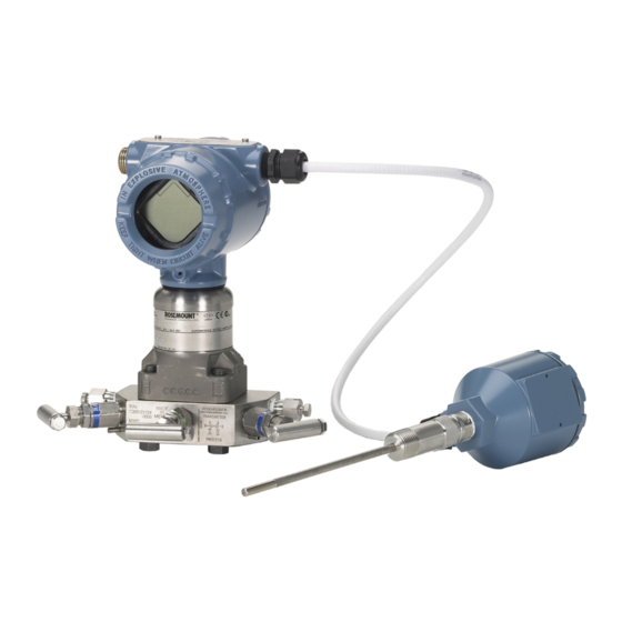
Emerson 3051SMV Reference Manual
Multivariable
transmitter
Hide thumbs
Also See for 3051SMV:
- Reference manual (80 pages) ,
- Quick start manual (36 pages) ,
- Reference manual (150 pages)

Related Manuals for Emerson 3051SMV


Summary of Contents for Emerson 3051SMV
- Page 1 Reference Manual 00809-0100-4853, Rev AB January 2017 ™ ™ Rosemount 3051SMV MultiVariable Transmitter ™ with F Fieldbus Protocol OUNDATION...
-
Page 3: Table Of Contents
Reference Manual Contents 00809-0100-4853, Rev AB January 2017 Contents 1Section 1: Introduction 1.1 Using this manual ..............1 1.2 Product overview . - Page 4 Contents Reference Manual 00809-0100-4853, Rev AB January 2017 3.3.1 General ..............18 3.3.2 Mechanical .
- Page 5 Reference Manual Contents 00809-0100-4853, Rev AB January 2017 5Section 5: Troubleshooting 5.1 Section overview ..............47 5.2 Safety messages.
- Page 6 Contents Reference Manual 00809-0100-4853, Rev AB January 2017 Contents...
- Page 7 ™ For information on Rosemount nuclear-qualified products, contact the local Emerson Sales Representative. Individuals who handle products exposed to a hazardous substance can avoid injury if they are informed of and understand the hazard.
- Page 8 Do not attempt to loosen or remove flange bolts while the transmitter is in service. Replacement equipment or spare parts not approved by Emerson for use as spare parts could reduce the pressure retaining capabilities of the transmitter and may render the instrument dangerous.
-
Page 9: Using This Manual
The following transmitters are covered in this manual. Table 1-1. Rosemount 3051SMV Fully Compensated Mass Flow (M) Transmitter Measurement type Description Differential pressure, static pressure, temperature Differential pressure and static pressure Table 1-2. -
Page 10: Product Recycling/Disposal
Introduction Reference Manual 00809-0100-4853, Rev AB January 2017 Table 1-3. Device Driver Information Release Review Review Device identification Device driver identification date instructions functionality NAMUR NAMUR OUNDATION OUNDATION Device Manual document Change hardware software Fieldbus Fieldbus universal revision (2)(3) number description revision revision... -
Page 11: Section Overview
This section contains information for the flow and device configuration of the Rosemount 3051S ™ ™ MultiVariable Fieldbus Transmitter (3051SMV). Each F Fieldbus host or OUNDATION OUNDATION configuration tool has different ways of displaying and performing operations. Some hosts will use Device Descriptions (DD) and DD methods to complete device configuration and will display data consistently across platforms. -
Page 12: Flow Configuration
2.3.1 Engineering Assistant 5.5.1 ver. 2 Engineering Assistant 5.5.1 ver. 2 is PC-based software that performs flow configuration for the Rosemount 3051SMV with the fully compensated mass flow feature board. It is available as a standalone ™ ™ application or as an AMS... - Page 13 Configuration January 2017 00809-0100-4853, Rev AB 3. If the device is at a non-commissioned address, use the Emerson USB Fieldbus Interface’s Configuration Utility to “Commission” the Device. Note The Emerson USB Fieldbus Interface can be configured to power the connected fieldbus device. Never attempt to use two power sources at the same time.
-
Page 14: Creating A Flow Configuration
Engineering Assistant 5.5.1 ver. 2 is designed to guide the user through the setup of the flow configuration for the Rosemount 3051SMV. This information will be used by the Engineering Assistant to create the flow configuration parameters that can be sent to the transmitter or saved for future use. - Page 15 Reference Manual Configuration January 2017 00809-0100-4853, Rev AB Depending on the fluid selected, Engineering Assistant 5.5.1 ver. 2 may bring up a screen for entering additional fluid information. 4. Select a primary element type, then enter the sizing information in the fields provided. 5.
- Page 16 11. When prompted, save the flow configuration to the computer. The file must be saved for review or to edit the mass flow configuration in the future. Note Fieldbus mass flow configuration files cannot be uploaded from the Rosemount 3051SMV. If OUNDATION the file is not saved, it cannot be retrieved.
-
Page 17: Sending A Flow Configuration To The Transmitter
Mass flow test calculation The mass flow test calculation method allows the user to verify the flow configuration of the Rosemount 3051SMV by entering expected values for the differential pressure, absolute pressure, and process temperature variables. Test calculation units are always in inH O @ 68 °F for differential pressure, psi for... -
Page 18: Variable Configuration
Configuration Reference Manual 00809-0100-4853, Rev AB January 2017 Variable configuration 2.4.1 Units configuration Units for transmitter variables are configured in the XD Scale parameter in each AI Block. Each AI Block is connected to a transmitter variable according to the Channel parameter in the AI Block. When the units in an AI Block are changed, the units of the connected channel variable will be changed in the Sensor Transducer Block or the Mass Flow Transducer Block accordingly. -
Page 19: Differential Pressure
Callendar-Van Dusen Coefficients The Rosemount 3051SMV accepts Callendar-Van Dusen constants from a calibrated RTD schedule and generates a special custom curve to match that specific sensor resistance vs. temperature performance. Matching the specific sensor curve with the transmitter configuration enhances the temperature measurement accuracy. -
Page 20: Variable Simulation
Reference Manual Configuration 00809-0100-4853, Rev AB January 2017 User-defined process temperature sensor limits Process temperature sensor limits can be changed to allow early detection of RTD failures. When the limits are exceeded, the transmitter will display a Process Temperature Out of Limits alert in the transmitter status, set the PT measurement status to uncertain, and will stop using the measured temperature value in the flow calculation. -
Page 21: Device Configuration
If the Units Type is set to custom specify up to six characters here to be displayed with the configured parameter. 2.5.2 Write lock The following configuration items are found in the Resource Block. The Rosemount 3051SMV Transmitter supports both hardware and software write lock. Locking the transmitter will prevent configuration changes until it is unlocked again. Configuration... -
Page 22: Device Capabilities
2.6.2 Link active scheduler The Rosemount 3051SMV can be designated to act as the backup Link Active Scheduler (LAS) in the event that the LAS is disconnected from the segment. As the backup LAS, the Rosemount 3051SMV will take over the management of communications until the host is restored. The host system may provide a configuration tool specifically designed to designate a particular device as a backup LAS. -
Page 23: Capabilities
Reference Manual Configuration January 2017 00809-0100-4853, Rev AB 2.6.3 Capabilities There are a total of 20 Virtual Communication Relationships (VCRs). Two are permanent and 18 are fully configurable by the host system. Twenty-five link objects are available. Table 2-1. Network Parameters Network parameter Value Slot Time... -
Page 24: Block Instantiation
2.6.5 Block instantiation The Rosemount 3051SMV supports the use of function block instantiation. When a device supports block instantiation, the number of blocks and block types can be defined to match specific application needs. The number of blocks that can be instantiated is only limited by the amount of memory within the device and the block types that are supported by the device. -
Page 25: Section Overview
3051S ™ ™ MultiVariable Fieldbus Transmitter (3051SMV). A Quick Start Guide is shipped with every OUNDATION transmitter to describe basic installation, wiring, and startup procedures. Dimensional drawings for each transmitter variation and mounting configuration are included in Appendix A: Specifications and Reference Data. -
Page 26: Considerations
Use only bolts supplied or sold by Emerson as spare parts. Replacement equipment or spare parts not approved by Emerson for use as spare parts could reduce the pressure retaining capabilities of the transmitter and may render the instrument dangerous. -
Page 27: Environmental
Reference Manual Installation 00809-0100-4853, Rev AB January 2017 3.3.3 Environmental Best practice is to mount the transmitter in an environment that has minimal ambient temperature change. The transmitter electronics temperature operating limits are –40 to 185 °F (–40 to 85 °C). Appendix A: Specifications and Reference Data lists the sensing element operating limits. - Page 28 Installation Reference Manual 00809-0100-4853, Rev AB January 2017 Steam flow applications 1. Place taps to the side of the line. 2. Mount beside or below the taps. 3. Fill impulse lines with water. Flow Figure 3-1. Mounting Bracket - Coplanar Flange Panel mount Pipe mount Figure 3-2.
- Page 29 If the transmitter installation requires assembly of a process flange, manifold, or flange adapters, follow these assembly guidelines to ensure a tight seal for optimal performance characteristics of the transmitter. Only use bolts supplied with the transmitter or sold by Emerson as spare parts. Figure 3-3 illustrates common transmitter assemblies with the bolt length required for proper transmitter assembly.
- Page 30 Installation Reference Manual 00809-0100-4853, Rev AB January 2017 Table 3-1. Torque Values for the Flange and Flange Adapter Bolts Bolt material Head markings Initial torque Final torque 300 in-lb 650 in-lb Carbon Steel (CS) 150 in-lb 300 in-lb Stainless Steel (SST) Figure 3-4.
-
Page 31: Tagging
Reference Manual Installation 00809-0100-4853, Rev AB January 2017 3.4.2 Tagging Commissioning (paper) tag To identify which device is at a particular location use the removable tag provided with the transmitter. Ensure the physical device tag (PD tag field) is properly entered in both places on the removable commissioning tag and tear off the bottom portion for each transmitter. -
Page 32: Rotate The Lcd Display
Installation Reference Manual 00809-0100-4853, Rev AB January 2017 3.4.4 Rotate the LCD display Transmitters ordered with the LCD display will be shipped with the display installed. In addition to housing rotation, the optional LCD display can be rotated in 90 degree increments by squeezing the two tabs, pulling out, rotating and snapping back into place. -
Page 33: Wire, Ground, And Power
Reference Manual Installation 00809-0100-4853, Rev AB January 2017 Figure 3-8. Simulate and Security Switches A. Security unlocked position D. Simulate disabled position B. Security switch E. Simulate switch C. Security locked position F. Simulate enabled position 3.4.6 Wire, ground, and power Use a copper wire of sufficient size to ensure the voltage across the transmitter power terminals does not drop below 9 Vdc. - Page 34 Installation Reference Manual 00809-0100-4853, Rev AB January 2017 4. Trim the cable shield as short as practical and insulate from touching the transmitter housing as indicated in Figure 3-9 Figure 3-10. Note Do NOT ground the cable shield at the transmitter; if the cable shield touches the transmitter housing, it can create ground loops and interfere with communications.
-
Page 35: Power Supply
The internal ground connection screw is inside the FIELD TERMINALS side of the electronics housing. This screw is identified by a ground symbol ( ). The ground connection screw is standard on all Rosemount 3051SMV Transmitters (see Figure 3-11). Installation... -
Page 36: 10Grounding
The transient protection terminal block can be ordered as an installed option (option code T1) or as a spare part to retrofit existing Rosemount 3051SMV Transmitters in the field. The lightning bolt symbol shown in Figure 3-13 identifies the transient protection terminal block. -
Page 37: 11Signal Termination
Use shielded four-wire cable for the process temperature connection. 2. Connect the RTD cable to the Rosemount 3051SMV by inserting the cable wires through the unused housing conduit and connect to the four screws on the transmitter terminal block. An appropriate cable gland should be used to seal the conduit opening around the cable. -
Page 38: Rosemount 305 And 304 Manifolds
A 3-wire Pt 100 RTD may be used with degraded performance. If connecting to a 3-wire RTD, use a 4-wire cable to connect the Rosemount 3051SMV terminal block to the RTD connection head. Within the RTD connection head, connect two of the same colored wires from the Rosemount 3051SMV to the single colored wire of the RTD sensor. -
Page 39: Rosemount 305 And 304 Manifolds
Traditional Wafer 3.5.1 Rosemount 305 Integral Manifold installation procedure To install a Rosemount 305 Integral Manifold to a Rosemount 3051SMV: ™ 1. Inspect the PTFE SuperModule O-rings. If the O-rings are undamaged, reusing them is recommended. If the O-rings are damaged (e.g. nicks), replace them with new O-rings. -
Page 40: Rosemount 305 Integral Manifold Installation Procedure
Improper installation or operation of manifolds may result in process leaks, which may cause death or serious injury. To install a traditional manifold to a Rosemount 3051SMV: 1. Align the traditional manifold with the transmitter flange. Use the four manifold bolts for alignment. - Page 41 Reference Manual Installation 00809-0100-4853, Rev AB January 2017 2. Open the equalize valve to equalize the pressure on both sides of the transmitter. The manifold is now in the proper configuration for performing a zero trim on the Drain/Vent Drain/Vent transmitter.
- Page 42 Installation Reference Manual 00809-0100-4853, Rev AB January 2017 2. Open the equalize valve on the high pressure (upstream) side of the transmitter. (Plugged) (Plugged) Equalize Equalize (open) (closed) Isolate Isolate (open) (closed) Process Drain vent Process (closed) 3. Open the equalize valve on the low pressure (downstream) side of the transmitter.
- Page 43 Reference Manual Installation 00809-0100-4853, Rev AB January 2017 Adjusting valve packing Over time, the packing material inside a manifold may require adjustment in order to continue to provide proper pressure retention. Not all manifolds have this adjustment capability. The manifold model number will indicate what type of stem seal or packing material has been used.
- Page 44 Installation Reference Manual 00809-0100-4853, Rev AB January 2017 Installation...
-
Page 45: Section Overview
™ This section contains information on operating and maintaining the Rosemount 3051S MultiVariable ™ Fieldbus Transmitter (3051SMV). Each F Fieldbus host or configuration tool has OUNDATION OUNDATION different ways of displaying and performing operations. Some hosts will use Device Descriptions (DD) and DD Methods to complete device configuration and will display data consistently across platforms. -
Page 46: Calibration
Do not attempt to loosen or remove flange bolts while the transmitter is in service. Replacement equipment or spare parts not approved by Emerson for use as spare parts could reduce the pressure retaining capabilities of the transmitter and may render the instrument dangerous. -
Page 47: Determining Necessary Sensor Trims
Reference Manual Operation and Maintenance 00809-0100-4853, Rev AB January 2017 4.3.3 Determining necessary sensor trims Bench calibration is not recommended for new instruments. The transmitter can be set back to factory settings using the Restore Factory Calibration. For transmitters that are field installed, the manifolds discussed in “Manifold operation”... -
Page 48: Static Pressure Sensor Calibration
Use calibration equipment that is at least three times as accurate as the pressure sensor of the Rosemount 3051SMV Transmitter. A reference pressure device is required to perform a full sensor trim. Allow the pressure input to stabilize for ten seconds before entering any values. -
Page 49: Process Temperature Sensor Calibration
Whenever the process flange or flange adapters are removed, visually inspect the PTFE O-rings. Emerson recommends reusing O-rings if possible. If the O-rings show any signs of damage, such as nicks or cuts, they should be replaced. 4.4.2... - Page 50 During disassembly, do not remove the instrument cover in explosive atmospheres when the circuit is live as this may result in serious injury or death. The Rosemount 3051SMV Transmitter electronics board is located opposite the field terminal side in the housing. To remove the electronics board, perform the following procedure: 1.
- Page 51 Reference Manual Operation and Maintenance 00809-0100-4853, Rev AB January 2017 Figure 4-2. Set Screw A. Housing rotation set screw ( -in.) Attach the sensor module assembly to the housing 1. Apply a light coat of low temperature silicon grease to the sensor module threads and O-ring. 2.
-
Page 52: Terminal Block
With optional process temperature connections temperature connections 1. Gently slide the terminal block into the housing, making sure the pins from the Rosemount 3051SMV housing properly engage the receptacles on the terminal block. 2. Tighten the captive screws on the terminal block. -
Page 53: Flange And Drain Vent
If installation uses a manifold, see “Manifold operation” on page 3. Inspect the sensor module PTFE O-rings. If the O-rings are undamaged, they may be reused. Emerson recommends reusing O-rings if possible. If the O-rings show any signs of damage, such as nicks or cuts, they should be replaced (part number 03151-9042-0001 for glass-filled PTFE and part number 03151-9042-0002 for graphite-filled PTFE). - Page 54 Operation and Maintenance Reference Manual 00809-0100-4853, Rev AB January 2017 b. If the installation requires a –14 NPT connection(s), use flange adapters and four 2.88-in. process flange/adapter bolts. c. Hold the flange adapters and adapter O-rings in place while finger-tightening the bolts. d.
-
Page 55: Section Overview
™ problems on the Rosemount 3051S MultiVariable Fieldbus Transmitter (3051SMV). OUNDATION If a malfunction is suspected despite the absence of any diagnostic messages on the communicator display, follow the procedures described to verify transmitter hardware and process connections are in good working order. -
Page 56: Measurement Troubleshooting
Replace Pt 100 sensor Sensor module • Check for obvious defects, such as a punctured isolating diaphragm or fill fluid loss, and if replacement is needed, contact the nearest Emerson Service Center. • Check for proper fill fluid characteristics (see Fill fluid for more information). -
Page 57: Fill Fluid
Reference Manual Troubleshooting 00809-0100-4853, Rev AB January 2017 5.3.1 Fill fluid The following performance limitations may inhibit efficient or safe operation. Critical applications should have appropriate diagnostic and backup systems in place. Pressure transmitters contain an internal fill fluid. It is used to transmit the process pressure through the isolating diaphragms to the pressure sensor module. -
Page 58: Alarms And Conditions
Troubleshooting Reference Manual 00809-0100-4853, Rev AB January 2017 Symptom Recommended actions Signal levels 1. Check for two terminators. 2. Check for excess cable length. 3. Check for bad power supply or conditioner. Segment noise 1. Check for incorrect grounding. 2. Check for correct shielded wire. Device does not stay 3. - Page 59 Reference Manual Troubleshooting 00809-0100-4853, Rev AB January 2017 Table 5-3. Failed–Fix Now Alert label display Description Recommended action message 1. Verify the conditions of the process where the transmitter is installed. Note: If a junction box is installed/utilized, check the connections for the RTD sensor.
- Page 60 Troubleshooting Reference Manual 00809-0100-4853, Rev AB January 2017 Table 5-5. Maintenance Required Alert label display Description Recommended action message 1. If using a temperature sensor in the process, enable the process temperature Process temperature Mass Flow measurement is not measurement. Missing Process CONFIG available for mass...
-
Page 61: Service Support
January 2017 Service support To expedite the return process outside of the United States, contact the nearest Emerson representative. Within the United States, call the Emerson Instrument and Valves Response Center using the 1-800-654-RSMT (7768) toll-free number. This center, available 24 hours a day, will assists with any needed information or materials. - Page 62 Reference Manual Troubleshooting 00809-0100-4853, Rev AB January 2017 Troubleshooting...
-
Page 63: Aappendix A: Specifications And Reference Data
Ultra for Flow is only available for Rosemount 3051S MultiVariable Transmitter (3051SMV) DP Ranges 2–3. For calibrated spans from 1:1 to 2:1 of URL. For DP range 1, 4 or 5, Classic MV and Ultra for Flow static pressure accuracy is ±0.055% of span on SP Range 4 only. For spans less than 5:1, ±(0.013[URL/Span])% of span. - Page 64 Warranty details can be found in Emerson Terms & Conditions of Sale, Document 63445, Rev G (10/06). Rosemount Ultra for Flow transmitters have a limited warranty of 15 years from date of shipment. All other provisions of Emerson standard limited warranty remain the same.
- Page 65 6 kV crest (0.5 μs–100 kHz) amplitude/60–500 Hz 2g). 20 μs) 3 kA crest (8 50 μs) 6 kV crest (1.2 Rosemount 3051SMV and 3051SF_1, 3, 5, 7 require shielded cable for the pro- cess temperature connection. Specifications and Reference Data...
-
Page 66: A.1.2 Functional Specifications
Reference Manual Specifications and Reference Data January 2017 00809-0100-4853, Rev AB A.1.2 Functional specifications Range and sensor limits Table A-1. Rosemount 3051SMV Differential Pressure Range and Sensor Limits Minimum span Range limits Ultra for Flow Classic Lower (LRL) Upper (URL) 0.50 inH... -
Page 67: Temperature Limits
Operates within 0.5 psia (0,03 bar) and the values in the Turn-on time table below: Performance within specifications less than ten seconds for Static pressure range (GP/AP) Rosemount 3051SMV (typical) after power is applied to the Range transmitter. 800 psi (55,15 bar) 2000 psi (137,90 bar) -
Page 68: A.1.3 Physical Specifications
Reference Manual Specifications and Reference Data January 2017 00809-0100-4853, Rev AB A.1.3 Physical specifications Coplanar sensor module housing SST: CF-3M (Cast 316L SST) Electrical connections Bolts –14 NPT, G , and M20 1.5 (CM20) conduit. Plated carbon steel per ASTM A449, Type 1 ... - Page 69 Shipping weights for Rosemount Weight in lb (kg) Item 3051SMV Aluminum standard cover 0.4 (0,2) ™ Rosemount 3051SMV with PlantWeb housing: SST standard cover 1.3 (0,6) 6.7 lb (3,1 kg) Aluminum display cover 0.7 (0,3) Table A-5. Transmitter Option Weights SST display cover 1.5 (0,7)
-
Page 70: A.2 Dimensional Drawings
Reference Manual Specifications and Reference Data January 2017 00809-0100-4853, Rev AB A.2 Dimensional drawings Process adapters (option D2) and Rosemount 305 Integral Manifolds must be ordered with the transmitter. Figure A-1. Transmitter with Coplanar Sensor Module and Coplanar Flange 4.51 (115) 4.20 (107) 8.53 (217) - Page 71 Specifications and Reference Data Reference Manual January 2017 00809-0100-4853, Rev AB Figure A-3. Coplanar Flange Mounting Configurations Pipe mount Panel mount 2.58 4.51 5.17 (131) (66) (115) 6.15 (156) 2.71 (71) 6.25 (159) 4.73 (120) 3.54 (90) Dimensions are in inches (millimeters). Figure A-4.
-
Page 72: A.3 Ordering Information
Specification and selection of product materials, options, or components must be made by the purchaser of the equipment. ® Table A-6. Rosemount 3051SMV HART and Fieldbus Ordering Information The starred offerings (★) represent the most common options and should be selected for best delivery. The non-starred offerings are subject to additional delivery lead time. - Page 73 January 2017 00809-0100-4853, Rev AB ® Table A-6. Rosemount 3051SMV HART and Fieldbus Ordering Information The starred offerings (★) represent the most common options and should be selected for best delivery. The non-starred offerings are subject to additional delivery lead time.
- Page 74 January 2017 00809-0100-4853, Rev AB ® Table A-6. Rosemount 3051SMV HART and Fieldbus Ordering Information The starred offerings (★) represent the most common options and should be selected for best delivery. The non-starred offerings are subject to additional delivery lead time.
- Page 75 January 2017 00809-0100-4853, Rev AB ® Table A-6. Rosemount 3051SMV HART and Fieldbus Ordering Information The starred offerings (★) represent the most common options and should be selected for best delivery. The non-starred offerings are subject to additional delivery lead time.
- Page 76 January 2017 00809-0100-4853, Rev AB ® Table A-6. Rosemount 3051SMV HART and Fieldbus Ordering Information The starred offerings (★) represent the most common options and should be selected for best delivery. The non-starred offerings are subject to additional delivery lead time.
- Page 77 January 2017 00809-0100-4853, Rev AB ® Table A-6. Rosemount 3051SMV HART and Fieldbus Ordering Information The starred offerings (★) represent the most common options and should be selected for best delivery. The non-starred offerings are subject to additional delivery lead time.
- Page 78 January 2017 00809-0100-4853, Rev AB ® Table A-6. Rosemount 3051SMV HART and Fieldbus Ordering Information The starred offerings (★) represent the most common options and should be selected for best delivery. The non-starred offerings are subject to additional delivery lead time.
- Page 79 (19) ★ –58 °F (–50 °C) cold temperature start-up Typical model number: 3051SMV 3 M 1 2 G 4 R 2 E12 A 1A B4 C2 M5 For detailed specifications see “Specifications” on page For Measurement Types 1 and 2, only available with DP range codes 2, 3, and 4, 316L SST and Alloy C-276 isolating diaphragm and silicone fill fluid.
- Page 80 Reference Manual Specifications and Reference Data January 2017 00809-0100-4853, Rev AB 32. Requires 316L SST or Alloy C-276 diaphragm material, assemble to Rosemount 305 Integral Manifold or DIN-compliant traditional flange process connection, and bolting option L8. Limited to differential pressure ranges 2-5. 33.
-
Page 81: A.4 Spare Parts List
Specifications and Reference Data Reference Manual January 2017 00809-0100-4853, Rev AB A.4 Spare parts list Part number Feature board and housing assembly Feature board kit without temperature input, direct process variable output 03151-9020-1000 Feature board kit without temperature input, mass flow output 03151-9020-1001 Feature board kit with temperature input, direct process variable output 03151-9020-1010... - Page 82 Reference Manual Specifications and Reference Data January 2017 00809-0100-4853, Rev AB Flange adapter kits (each kit contains adapters, bolts, and O-ring for one DP transmitter or Part number two GP/AP transmitters) CS bolts, glass filled PTFE O-rings SST adapters 03031-1300-0002 Cast C-276 adapters 03031-1300-0003 Cast alloy 400 adapters...
- Page 83 Specifications and Reference Data Reference Manual January 2017 00809-0100-4853, Rev AB Part number O-ring packages (package of 12) Electronic housing, cover (standard and LCD display) 03151-9040-0001 Electronic housing, module 03151-9041-0001 Process flange, glass-filled PTFE 03151-9042-0001 Process flange, graphite-filled PTFE 03151-9042-0002 Process adapter, glass-filled PTFE 03151-9043-0001 Process adapter, graphite-filled PTFE...
- Page 84 Reference Manual Specifications and Reference Data January 2017 00809-0100-4853, Rev AB Traditional flange Part number Differential flange and adapter bolt kit Carbon steel (set of 8) 03151-9283-0001 316 SST (set of 8) 03151-9283-0002 ANSI/ASTM-A-193-B7M (set of 8) 03151-9283-0003 Alloy K-500 (set of 8) 03151-9283-0004 Gage/absolute flange and adapter bolt kit Carbon steel (set of 6)
- Page 85 Specifications and Reference Data Reference Manual January 2017 00809-0100-4853, Rev AB RTD input with 24 ft. (7,32 m) of ATEX/IEXCEx flameproof cable 03151-9066-0124 RTD input with 75 ft. (22,86 m) of ATEX/IEXCEx flameproof cable 03151-9066-0175 AL housing with M20 1.5 conduit- kit includes cable and cable glands RTD input with 34-in.
- Page 86 Reference Manual Specifications and Reference Data January 2017 00809-0100-4853, Rev AB SST housing with G conduit- kit includes cable and cable glands RTD input with 34-in. (86 cm) of shielded cable 03151-9064-0002 RTD input with 12 ft. (3,66 m) of shielded cable 03151-9064-0012 RTD input with 24 ft.
-
Page 87: European Directive Information
Quick Start Guide. The most recent revision FM Class 3616 – 2011, of the EU Declaration of Conformity can be found at FM Class 3810 – 2005, Emerson.com/Rosemount. ® ANSI/NEMA 250 – 2003 Markings: XP CL I, DIV 1, GP B, C, D; T5;... - Page 88 Reference Manual Product Certifications January 2017 00809-0100-4853, Rev AB US FISCO Intrinsically Safe Canada FISCO Intrinsically Safe Certificate: FM16US0233 Certificate: 143113 Standards: FM Class 3600 – 2011, Standards: CAN/CSA C22.2 No. 0-10, FM Class 3610 – 2010, CSA Std C22.2 No. 25-1966, FM Class 3611 –...
- Page 89 Product Certifications Reference Manual January 2017 00809-0100-4853, Rev AB 2. Flameproof joints are not intended for repair. ATEX FISCO Certificate: Baseefa08ATEX0064X 3. Non-standard paint options may cause risk from Standards: EN 60079-0:2012, EN 60079-11:2012 electrostatic discharge. Avoid installations that could Markings: II 1 G Ex ia IICT4 Ga, T4(–60 °C ≤...
- Page 90 Product Certifications Reference Manual January 2017 00809-0100-4853, Rev AB International E7 IECEx Flameproof and Dust SuperModule OUNDATION Parameter HART Fieldbus only Certificate: IECEx KEM 08.0010X (Flameproof) Standards: IEC 60079-0:2011, IEC 60079-1:2014, IEC Voltage U 30 V 30 V 7.14 V 60079-26:2014 Current I 300 mA...
- Page 91 Product Certifications Reference Manual January 2017 00809-0100-4853, Rev AB Brazil RTD (for 3051SFx) RTD for 3051SFx Parameter (HART) (Fieldbus) E2 INMETRO Flameproof Voltage U 30 V 30 V Certificate: UL-BR 15.0393X Standards: ABNT NBR IEC 60079-0:2008 + Current I 2.31 mA 18.24 mA Corrigendum 1:2011, ABNT NBR IEC Power P...
- Page 92 E3 China Flameproof and Dust Ignition-proof inspection bodies with Ex d IIC Gb or Ex d IIC Gb DIP Certificate: 3051SMV: GYJ14.1039X [Mfg USA, China, A20 [Flowmeters] IP66 type of protection should be Singapore] used.
- Page 93 Product Certifications Reference Manual January 2017 00809-0100-4853, Rev AB 3. Ambient temperature range: –60 °C +70 °C 11. During installation, use and maintenance of this product, observe following standards: 4. Intrinsically safe electric parameters: GB3836.13-2013 “Electrical apparatus for explosive gas atmospheres Part 13: Repair and overhaul for Maximum Maximum Maximum...
- Page 94 Product Certifications Reference Manual January 2017 00809-0100-4853, Rev AB Combinations SDN Det Norske Veritas (DNV) Type Approval Certificate: A-14186 K1 Combination of E1, I1, N1, and ND Intended Use: Det Norske Veritas' Rules for Classification of Ships, High Speed & K2 Combination of E2 and I2 Light Craft, and Det Norske Veritas' K5 Combination of E5 and I5...
-
Page 95: B.4 Installation Drawings
Product Certifications Reference Manual January 2017 00809-0100-4853, Rev AB B.4 Installation drawings Figure B-1. Factory Mutual (FM) PRINTED COPIES ARE UNCONTROLLED Product Certifications... - Page 96 Product Certifications Reference Manual January 2017 00809-0100-4853, Rev AB PRINTED COPIES ARE UNCONTROLLED Product Certifications...
- Page 97 Product Certifications Reference Manual January 2017 00809-0100-4853, Rev AB PRINTED COPIES ARE UNCONTROLLED Product Certifications...
- Page 98 Product Certifications Reference Manual January 2017 00809-0100-4853, Rev AB Product Certifications...
- Page 99 Product Certifications Reference Manual January 2017 00809-0100-4853, Rev AB Product Certifications...
- Page 100 Product Certifications Reference Manual January 2017 00809-0100-4853, Rev AB PRINTED COPIES ARE UNCONTROLLED Product Certifications...
- Page 101 Product Certifications Reference Manual January 2017 00809-0100-4853, Rev AB Product Certifications...
- Page 102 Reference Manual Product Certifications January 2017 00809-0100-4853, Rev AB PRINTED COPIES ARE UNCONTROLLED Product Certifications...
- Page 103 Product Certifications Reference Manual January 2017 00809-0100-4853, Rev AB Figure B-2. Canadian Standards Association (CSA) PRINTED COPIES ARE UNCONTROLLED Product Certifications...
- Page 104 Product Certifications Reference Manual January 2017 00809-0100-4853, Rev AB PRINTED COPIES ARE UNCONTROLLED Product Certifications...
- Page 105 Product Certifications Reference Manual January 2017 00809-0100-4853, Rev AB PRINTED COPIES ARE UNCONTROLLED Product Certifications...
- Page 106 Product Certifications Reference Manual January 2017 00809-0100-4853, Rev AB Product Certifications...
- Page 107 Product Certifications Reference Manual January 2017 00809-0100-4853, Rev AB PRINTED COPIES ARE UNCONTROLLED Product Certifications...
- Page 108 Product Certifications Reference Manual January 2017 00809-0100-4853, Rev AB Product Certifications...
- Page 109 Product Certifications Reference Manual January 2017 00809-0100-4853, Rev AB PRINTED COPIES ARE UNCONTROLLED Product Certifications...
- Page 110 Reference Manual Product Certifications January 2017 00809-0100-4853, Rev AB PRINTED COPIES ARE UNCONTROLLED Product Certifications...
- Page 112 Emerson Automation Solutions Asia Pacific Pte Ltd Conditions of Sale page. 1 Pandan Crescent The Emerson logo is a trademark and service mark of Emerson Electric Co. AMS, MultiVariable, PlantWeb, SNAP-ON, SuperModule, THUM Adapter, Singapore 128461 Rosemount, and Rosemount logotype are trademarks of Emerson.
Need help?
Do you have a question about the 3051SMV and is the answer not in the manual?
Questions and answers