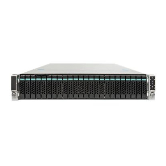
Page 1
® Intel Storage Server System JBOD 2000 Family Service Guide ® A Guide for Technically Qualified Assemblers of Intel identified Subassemblies/Products Revision 1.1 Order Number: G85063-002...
Page 2
Intel’s own chassis are designed and tested to meet the intended thermal requirements of these components when the fully integrated system is used together. It is the responsibility of the system integrator that chooses not to use Intel developed server building blocks to consult vendor datasheets and operating parameters to determine the amount of airflow required for their specific application and environmental conditions.
Instrucciones de seguridad importantes Lea todas las declaraciones de seguridad y precaució n de este documento antes de realizar cualquiera de las instrucciones. Vea Intel Server Boards and Server Chassis Safety Information en ® el Intel Server Deployment Toolkit 3.0 CD y/o en http://www.intel.com/support/motherboards/server/sb/cs-010770.htm.
Page 4
Use a conductive foam pad if available but not the board wrapper. Do not slide board over any surface. ® Intel JBOD2000 Family Service Guide...
JBOD chassis, a list of accessories or other components you may need, troubleshooting information, ® and instructions on how to add and replace components on the Intel JBOD 2000 Family System products. For the latest revision of this manual, go to http://www.intel.com/support.
Installing and Removing the Storage Front Panel ..............29 Installing the Storage Front Panel ................29 Removing the Storage Front Panel ................30 Appendix A: Technical Reference ................ 31 Power Supply Input Voltages ..................31 ® Intel JBOD2000 Family Service Guide...
Page 7
Table of Contents Power Supply Output Voltages ..................31 System Environmental Specifications ................31 Appendix B: Regulatory and Compliance Information ......... 33 Appendix C: Getting Help ..................34 Warranty Information ....................34 ® Intel JBOD2000 Family Service Guide...
Quick Reference Label provided on the inside of the chassis cover to assist in identifying components. ® Figure 2. Intel JBOD System Family Components Hot Swap Hard Drive Bay and Front Panel Options Figure 3. 12 x 3.5” Drive JBOD2000 Front View Figure 4.
Description Power Button w/Integrated LED System Status LED Figure 5. Front Panel Options Back Panel Figure 6. Single-port Backplane JBOD2000 Back View Label Description SFF-8088 receptacle (label: A PRI) SFF-8088 receptacle (label: B PRI) ® Intel JBOD2000 Family Service Guide...
Page 12
SFF-8088 receptacle (label: A PRI) SFF-8088 receptacle (label: B PRI) SFF-8088 receptacle (label: A SEC) SFF-8088 receptacle (label: B SEC) SFF-8088 receptacle (label: C SEC) SFF-8088 receptacle (label: C PRI) PSU 1 PSU 2 ® Intel JBOD2000 Family Service Guide...
Page 13
Note: Drives can consume up to 17 watts of power each. Drives must be specified to run at a maximum ambient temperature of 45 ° ® Note: The Intel System Family does not support all SAS or Serial ATA (SATA) hard drives. For a JBOD “Additional Information and web link to a list of supported hard drives, see Software”.
Page 14
Power Connectors C Connector Figure 9. 12 x 3.5-inch Hard Drive Backplane Components (Rear View) 8 x 2.5-inch Hard Drive Backplane SAS/SATA Hot-swap Connectors Figure 4. 8 x 2.5-inch Hard Drive Backplane Components (Front View) ® Intel JBOD2000 Family Service Guide...
Page 15
JBOD System Features C Out Connector Mini-SAS Connectors C In Connector Power Connector Figure 11. 8 x 2.5-inch Hard Drive Backplane Components (Rear View) JBOD2312S2SP Interconnection ® Intel JBOD2000 Family Service Guide...
Page 16
JBOD System Features Figure 5. 12x3.5” Single-port JBOD 2000 Interconnection Diagram Table 1. 12x3.5” Single-port JBOD 2000 Internal Components Label Description Label Description Front Panel Front Panel Cable HSBP Power Daisy Chain Cable Three 60mm System Fans 2x15-pin Front Panel Connector on PDB...
SMBus Cable Primary SAS Expander Fan Cable 12x 3.5” HSBP Three mini-SAS Connectors on HSBP with port number JBOD2224S2DP Interconnection Figure 6. 2U 24x2.5” Dual-port JBOD2000 Interconnection Diagram Table 2. 2U 24x2.5” Dual-port JBOD2000 Components ® Intel JBOD2000 Family Service Guide...
Page 18
SMBus Cable Second Expander Primary SAS Expander Second SAS Expander Fan Cable 12 mini-SAS Connectors on HSBP Three 8x 2.5” Dual-port HSBPs (each HSBP has four mini-SAS connectors) ® 36-Port Internal Intel RAID Expander Card ® Intel JBOD2000 Family Service Guide...
Page 19
JBOD System Features Figure 7. SAS Expander Table 3. Primary SAS Expander in 12x3.5” Single-port JBOD 2000 Connector Mapping Primary Interconnection SAS Expander Label Port 0 To Backplane Port 0 Port 1 To Backplane Port 1 Port 2 To Backplane Port 2...
Page 20
JBOD System Features Table 5. Second SAS Expander in 24x2.5” Dual-port JBOD 2000 Connector Mapping Second Interconnection SAS Expander Label Port 0 To Backplane Port 0B Port 1 To Backplane Port 1B Port 2 To Backplane Port 2B Port 3...
Use caution to make sure no cables or wires are pinched and that the airflow from the fans is not blocked. Fan Connections Use the figures below to determine the proper fan connections. Figure 8. System Fan Order ® Intel JBOD2000 Family Service Guide...
Figure 10. Installing the Front Bezel Intel also provides an optional plastic badge for customer to use. To install the badge to the bezel, attach the badge onto the bezel until the hooks at the rear of the badge click into the bezel.
1. Observe the safety and ESD precautions at the beginning of this book. 2. Turn off all peripheral devices connected to the server. Turn off the server. ® Intel JBOD2000 Family Service Guide...
Installing a Hard Disk Drive into 3.5” Hard Drive Carrier 1. Remove the drive carrier by pressing the green button and opening the lever (see letter “A”). Slide the carrier out (see letter “B”). ® Intel JBOD2000 Family Service Guide...
Page 25
Secure the bracket with three screws as shown (see letter “d2”). Slide the 2.5" HDD into the bracket to align the screw holes with the right and left rail (see letter “d3”). Secure the hard disk drive using the four screws for 2.5" HDD (see letter “d4”). ® Intel JBOD2000 Family Service Guide...
2. Remove the four screws securing the plastic drive blank from the 2.5" HDD carrier (see letter “C”). Disengage the plastic drive blank from the HDD carrier. Remove the plastic drive blank from the 2.5" HDD carrier (see letter “D”). ® Intel JBOD2000 Family Service Guide...
The power supply can be replaced if it fails. To replace the power supply, follow these steps: 1. Do one of the following: If a filler panel is installed, use the 'finger hole' to remove the filler panel (see letter “A”). ® Intel JBOD2000 Family Service Guide...
Page 28
Insert the power supply module into the power supply cage and push all the way until it clicks into place (see letter “B”). Figure 26. Installing the power supply module If no power supply is to be installed, install the filler panel into the power supply cage. ® Intel JBOD2000 Family Service Guide...
3. Lift the expander board from the JBOD system. Installing the SAS Expander 1. Place the SAS Expander into the JBOD system (see letter “A”) 2. Secure the SAS Expander with three screws (see letter “B”). ® Intel JBOD2000 Family Service Guide...
2. Disconnect all cables from the power distribution board and remember the connection locations. 3. Remove the six screws from the power distribution board (see letter “A”). Figure 30. Removing the Power Distribution Board 4. Lift the power distribution board from the JBOD system (see letter “B”). ® Intel JBOD2000 Family Service Guide...
3. Connect all cables back into the power distribution board connectors. Replacing a System Fan 1. Pull system fan straight up to remove it from the fan holder. 2. Replace the system fan. Figure 32. Replacing a system fan ® Intel JBOD2000 Family Service Guide...
5. Pull up the backplane (see letter “D”). Remove the backplane from the server chassis (see letter “E”). Figure 34. Removing 3.5” hard drive backplane - remove the backplane Installing the 3.5” Hard Drive Backplane ® Intel JBOD2000 Family Service Guide...
Page 33
7. With the lever open, insert the hard disk drive assembly into the chassis (see letter “G”). Push in the lever to lock it into place (see letter “H”). Repeat step G and H to make sure all hard drive assemblies are in place. ® Intel JBOD2000 Family Service Guide...
5. Slide the hard drive cage out of the server chassis (see letter “D”). Figure 39. Removing 2.5” hard drive backplane – remove the hard drive cage 6. Remove the screw from the backplane board (see letter “E”). ® Intel JBOD2000 Family Service Guide...
Page 35
4. Secure the hard drive cage with the three screws (see letter “E”). Figure 42. Installing 2.5” hard drive backplane – install hard drive cage 5. Insert the stiffener into server chassis (see letter “F”). ® Intel JBOD2000 Family Service Guide...
Figure 44. Installing the Rack Handle Removing the Rack Handles Remove the two screws holding the rack handle in place, and remove the rack handle from the server system as shown. ® Intel JBOD2000 Family Service Guide...
4. Attach the storage front panel to the rack handle on the right side of serve chassis (see letter “D”); 5. Fasten the four screws to secure the storage front panel (see letter “E”). ® Intel JBOD2000 Family Service Guide...
5. Remove the storage front panel from the side wall of server chassis (see letter “E”); Figure 49. Installing the interposer card 6. Connect the front panel control cable from mother board to the standard front control panel if needed. See Cable Routing for more details. ® Intel JBOD2000 Family Service Guide...
Non-palletized free fall in height 24 inches (≧40 lbs to < 80 lbs) Vibration, unpackaged 5 Hz to 500 Hz, 2.20 g RMS random ® +/-12 KV except I/O port +/- 8 KV per Intel Environmental test specification ® Intel...
Page 40
Appendix A: Technical Reference Parameter Limits 460 Watt Max – 1570 BTU/hour System Cooling Requirement in BTU/Hr ® Intel JBOD2000 Family Service Guide...
Appendix B: Regulatory and Compliance Information Appendix B: Regulatory and Compliance Information Please refer to the Server Products Regulatory and Safety document for the product regulatory compliance reference. The document can be downloaded from http://www.intel.com/support/server. ® Intel JBOD2000 Family Service Guide...
— Server and chassis accessory parts list for ordering upgrades or spare parts — A searchable knowledgebase to search for product information throughout the support site If you are still unable to obtain a solution to your issue, send an email to Intel’s technical support center using the online form available at http://www.intel.com/support/feedback.htm?group=server.
Need help?
Do you have a question about the JBOD 2000 and is the answer not in the manual?
Questions and answers