Sign In
Upload
Manuals
Brands
Intel Manuals
Storage
JBOD 2000 Family
Intel JBOD 2000 Family Manuals
Manuals and User Guides for Intel JBOD 2000 Family. We have
3
Intel JBOD 2000 Family manuals available for free PDF download: Hardware Manual, Service Manual, Quick Installation User's Manual
Intel JBOD 2000 Family Hardware Manual (63 pages)
Storage Server System
Brand:
Intel
| Category:
Storage
| Size: 4.16 MB
Table of Contents
Revision History
2
Table of Contents
4
1 Introduction
11
Server Product Use Disclaimer
11
Product Errata
11
2 Product Family Overview
12
Figure 1. 24 X 2.5" Drive JBOD 2000 Product Drawing
12
Table 1. System Feature Set
12
Figure 2. 12 X 3.5" Drive JBOD 2000 Product Drawing
13
Chassis Dimensions
14
Figure 3. Chassis Dimensions
14
System Level Environmental Limits
15
Table 2. System Environmental Limits Summary
15
System Features and Options Overview
17
Hot Swap Hard Drive Bay and Front Panel Options
17
Figure 4. System Components Overview
17
Figure 5. 12 X 3.5" Drive JBOD2000 Front View
17
Figure 6. 24 X 2.5" Drive JBOD2000 Front View
17
Front Panel Options
18
Figure 7. Front Panel Options
18
Table 3. Power LED Functional States
18
Table 4. System Status LED State Definitions
18
Back Panel Features
20
Figure 8. Single-Port Backplane JBOD2000 Back View
20
Figure 9. Dual-Port Backplane JBOD2000 Back View
20
3 System Storage and Peripheral Drive Bays Overview
21
2.5" Hard Disk Drive Support
21
Figure 10. 2.5" Hard Drive Bay - 24-Drive Configuration
21
Figure 11. 2.5" Drive Tray Assembly
21
Figure 12. Status and Activity LED on 2.5" Drive Tray
22
Table 5. Drive Status LED States
22
Table 6. Drive Activity LED States
22
2.5" Drive Hot-Swap Backplane Overview
23
Figure 13. 2.5" Hot-Swap Backplane and Drive Bay Assembly
23
Figure 14. SFF-8482 Connector on HSBP
23
Cypress* CY8C22545 Enclosure Management Controller
24
Figure 15. Components on Dual Port 2.5" HSBP
24
Hard Disk Drive Support
25
Figure 16. 3.5" Hard Drive Bay - 12-Drive Configuration
25
Figure 17. 3.5" Drive Tray Assembly
25
Figure 18. Status and Activity LED on 3.5" Drive Tray
25
Table 7. Status LED Status
25
3.5" Drive Hot-Swap Backplane Overview
26
Figure 19. 3.5" Hot-Swap Backplane and Drive Bay Assembly
26
Figure 20. SFF-8482 Connector on 3.5" HSBP
26
Table 8. Activity LED Status
26
Cypress* CY8C22545 Enclosure Management Controller
27
Figure 21. Components on 3.5" HSBP
27
4 Power Subsystem
28
Figure 22. Power Supply Assembly
28
Power Distribution Board (PDB)
29
Figure 23. Power Distribution Board (PDB)
29
Figure 24. PDB Component Placement
30
Figure 25. Fan Fault LED Block Diagram
32
Mechanical Overview
33
Figure 26. Power Supply Module Mechanical Drawing
33
Figure 27. Power Supply Module
33
Figure 28. AC Power Supply - Connector View
33
Power Connectors
34
Power Supply Module Card Edge Connector
34
Table 9. Power Supply Module Output Power Connector Pin-Out
34
Hot-Swap Backplane Power Connector
35
Power Supply Module Efficiency
35
AC Power Cord Specification Requirements
35
Figure 29. AC Power Cord
35
Table 10. Hot-Swap Backplane Power Connector Pin-Out ("HSBP PWR")
35
Table 11. 460 Watt Power Supply Efficiency (Gold)
35
Table 12. AC Power Cord Specifications
35
AC Input Specifications
36
Power Factor
36
AC Input Voltage Specification
36
AC Line Isolation Requirements
36
AC Line Dropout/Holdup
36
Table 13. Power Factor
36
Table 14. AC Input Voltage Range
36
AC Line Fuse
37
AC Inrush
37
AC Line Transient Specification
37
Table 15. AC Line Dropout/Holdup
37
Table 16. AC Line Sag Transient Performance
37
Susceptibility Requirements
38
Electrostatic Discharge Susceptibility
38
Fast Transient/Burst
38
Radiated Immunity
38
Surge Immunity
38
Table 17. AC Line Surge Transient Performance
38
Table 18. Performance Criteria
38
Voltage Interruptions
39
Protection Circuits
39
Over Current Protection (OCP)
39
Over Voltage Protection (OVP)
39
Table 19. 460 Watt Power Supply over Current Protection
39
Over Temperature Protection (OTP)
40
Table 20. over Voltage Protection (OVP) Limits
40
Power Supply Status LED
41
Table 21. LED Indicators
41
5 Thermal Management
42
Thermal Operation and Configuration Requirements
42
Thermal Management Overview
42
Thermal Sensor Input for Fan Speed Control
43
System Fans
43
Figure 30. System Fan Identification
43
Power Supply Module Fan
44
Figure 31. System Fan Assembly
44
Table 22. System Fan Connector Pin-Out
44
6 JBOD 2000 Internal Connection Overview
45
Expander Board
45
Figure 32. Internal SAS Expander Location
46
JBOD SAS Interface Board
47
JBOD SAS Interface Board Port Numbering
47
Figure 33. JBOD 2000 SAS Interface Board Port Number
47
Pin-Outs
48
Table 23. SGPIO Headers Pin-Out
48
Figure 34. 12X3.5" Single-Port JBOD 2000 Interconnection Diagram
49
JBOD2312S2SP Interconnection
49
Figure 35. Primary SAS Expander
50
Table 24. 12X3.5" Single-Port JBOD 2000 Internal Components
50
Table 25. Primary SAS Expander in 12X3.5" Single-Port JBOD 2000 Connector Mapping
51
Figure 36. 2U 24X2.5" Dual-Port JBOD2000 Interconnection Diagram
52
JBOD2224S2DP Interconnection
52
Table 26. 2U 24X2.5" Dual-Port JBOD2000 Components
53
Figure 37. Secondary SAS Expander
54
Table 27. Primary SAS Expander in 24X2.5" Dual-Port JBOD 2000 Connector Mapping
54
Table 28. Second SAS Expander in 24X2.5" Dual-Port JBOD 2000 Connector Mapping
54
7 JBOD 2000 External SAS Connection Mode Overview
55
External SAS Controller Support
55
External SAS Cable
55
Figure 38. SFF-8088 Mini-SAS Cable
55
Hard Drive Type
56
JBOD Cascade
56
Single-Port JBOD 2000 External Connection Mode
56
Single JBOD 2000 Connection
56
Figure 39. Single JBOD 2000 Connection
56
Two JBOD 2000 Cascade
57
Figure 40. Two Single-Port JBOD 2000 Cascade
57
Figure 41. Two Groups of Cascaded Single-Port JBOD 2000
57
Dual-Path Connection
58
Dual-Path with Cascaded JBOD 2000
58
Figure 42. Dual-Path Connection
58
Figure 43. Dual-Path with Cascaded JBOD 2000
58
Dual-Port JBOD 2000 External Connection Mode
59
Dual-Domain SAS for Dual-Port JBOD 2000
59
Figure 44. Dual-Domain SAS for Dual-Port JBOD 2000
59
Dual-Domain SAS for Cascaded Dual-Port JBOD 2000
60
Figure 45. Two SAS Controllers Dual-Domain SAS Connection
60
Figure 46. Dual-Domain SAS for Cascaded Dual-Port JBOD 2000
60
Dual-Domain SAS for Two-Node Cluster
61
Figure 47. Dual-Domain SAS for a Two-Node Cluster
61
Figure 48. Cascaded JBOD 2000 for a Two-Node Cluster
62
Reference Documents
63
Advertisement
Intel JBOD 2000 Family Service Manual (42 pages)
Storage Server System
Brand:
Intel
| Category:
Server
| Size: 1.15 MB
Table of Contents
Safety Information
3
Preface
5
Table of Contents
6
JBOD System Features
9
JBOD System Feature Overview
9
JBOD System Components
10
Hot Swap Hard Drive Bay and Front Panel Options
10
Front Panel
11
Back Panel
11
JBOD2224S2DP Interconnection
17
Hardware Installations and Upgrades
21
Before You Begin
21
Tools and Supplies Needed
21
System Reference
21
Fan Connections
21
Removing and Installing the Front Bezel
22
Removing the Front Bezel
22
Installing the Front Bezel
22
Removing and Installing the System Cover
23
Removing the System Cover
23
Installing the System Cover
24
Installing a Hot-Swap Hard Disk Drive
24
Installing a Hard Disk Drive into 3.5" Hard Drive Carrier
24
Installing a Hard Disk Drive into 2.5" Hard Drive Carrier
26
Replacing the Power Supply
27
Installing and Removing the SAS Expander
29
Removing the SAS Expander
29
Installing the SAS Expander
29
Installing and Removing the Power Distribution Board
30
Removing the Power Distribution Board
30
Installing the Power Distribution Board
31
Replacing a System Fan
31
Replacing the Backplane
32
Replacing the 3.5" Hard Drive Backplane
32
Replacing the 2.5" Hard Drive Backplane
34
Installing and Removing the Rack Handles
36
Installing the Rack Handles
36
Removing the Rack Handles
36
Installing and Removing the Storage Front Panel
37
Installing the Storage Front Panel
37
Removing the Storage Front Panel
38
Appendix A: Technical Reference
39
Power Supply Input Voltages
39
Power Supply Output Voltages
39
System Environmental Specifications
39
Appendix B: Regulatory and Compliance Information
41
Appendix C: Getting Help
42
Warranty Information
42
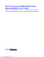
Intel JBOD 2000 Family Quick Installation User's Manual (15 pages)
Intel Storage System JBOD 2000 Family
Brand:
Intel
| Category:
Storage
| Size: 0.87 MB
Table of Contents
Table of Contents
3
Safety Information
5
Important Safety Instructions
5
Wichtige Sicherheitshinweise
5
General Installation Process
7
Before You Begin
8
Tools and Supplies Needed
8
System Reference
8
Cable Routing
8
Installing a Hot-Swap Hard Disk Drive
8
Installing a Hard Disk Drive into 3.5" Hard Drive Carrier
9
Figure 1. Installing Hard Disk Drive - Removing 3.5" HDD Carrier
9
Figure 2. Installing Hard Disk Drive - Removing 3.5" HDD Interface Bracket
9
Figure 3. Installing Hard Disk Drive - Installing 3.5" HDD
9
Figure 4. Installing Hard Disk Drive - Installing 2.5" HDD
10
Figure 5. Installing Hard Disk Drive - Inserting 3.5" HDD Assembly
10
Installing a Hard Disk Drive into 2.5" Hard Drive Carrier
11
Figure 6. Installing Hard Disk Drive - Removing 2.5" HDD Carrier
11
Figure 7. Installing Hard Disk Drive - Removing Plastic Drive Blank
11
Figure 8. Installing Hard Disk Drive - Installing 2.5" HDD
11
Installing Second Power Supply Module (Optional)
12
Figure 9. Installing Hard Disk Drive - Inserting 2.5" HDD Assembly
12
Figure 10. Removing the Filler Panel
12
Figure 11. Installing the Power Supply Module
12
Installing the Rack Handles
13
Figure 12. Removing the Power Supply Module
13
Figure 13. Installing the Rack Hand
13
Finishing up
14
Figure 14. Connecting Intel Storage System JBOD 2000 Family to RAID Controller
14
Warranty Information
15
Advertisement
Advertisement
Related Products
Intel JBOD2312S3SP
Intel JBOD 2000 Series
Intel JBOD2000S3SP
Intel JBOD2224S2DP
Intel JBOD2312S2SP
Intel Celeron J3355
Intel Celeron J3455
Intel 320 Series
Intel 320 Series SSD
Intel 530 Series
Intel Categories
Motherboard
Computer Hardware
Server
Server Board
Desktop
More Intel Manuals
Login
Sign In
OR
Sign in with Facebook
Sign in with Google
Upload manual
Upload from disk
Upload from URL