Intel JBOD 2000 Hardware Manual
Storage server system
Hide thumbs
Also See for JBOD 2000:
- Quick installation user's manual (15 pages) ,
- Service manual (42 pages)

Related Manuals for Intel JBOD 2000


Summary of Contents for Intel JBOD 2000
- Page 1 Intel Storage Server System JBOD ® 2000 Family Hardware Guide Revision 1.42 November 2015...
-
Page 2: Revision History
Revision History Intel® Storage Server System JBOD 2000 Family Hardware Guide Revision History Date Revision Modifications Number December 2012 Pre-production release. March 2013 First release. July 2013 1.05 Removed Chapter 9 and Appendix A. September 2013 Restructured the document. ... - Page 3 INFRINGEMENT OF ANY PATENT, COPYRIGHT OR OTHER INTELLECTUAL PROPERTY RIGHT. A "Mission Critical Application" is any application in which failure of the Intel Product could result, directly or indirectly, in personal injury or death. SHOULD YOU PURCHASE OR USE INTEL'S PRODUCTS FOR ANY SUCH MISSION...
-
Page 4: Table Of Contents
Table of Contents Intel® Storage Server System JBOD 2000 Family Hardware Guide Table of Contents 1. Introduction ........................1 Server Product Use Disclaimer ................1 Product Errata ......................1 2. Product Family Overview ....................2 Chassis Dimensions ....................4 System Level Environmental Limits ................ 5 System Features and Options Overview .............. - Page 5 Pin-outs ........................ 38 6.3.1 JBOD2312S2SP Interconnection ................. 39 6.3.2 JBOD2224S2DP Interconnection ................. 42 7. JBOD 2000 External SAS Connection Mode Overview ..........45 External SAS Controller Support ................45 External SAS Cable....................45 Hard Drive Type ....................46 JBOD Cascade ....................46 Single-port JBOD 2000 External Connection Mode ..........
- Page 6 Intel® Storage Server System JBOD 2000 Family Hardware Guide List of Figures Figure 1. 24 x 2.5” Drive JBOD 2000 Product Drawing ............... 2 Figure 2. 12 x 3.5” Drive JBOD 2000 Product Drawing ............... 3 Figure 3. Chassis Dimensions ..................... 4 Figure 4.
- Page 7 Intel® Storage Server System JBOD 2000 Family Hardware Guide List of Figures Figure 40. Two Single-port JBOD 2000 Cascade ..............47 Figure 41. Two Groups of Cascaded Single-port JBOD 2000 ........... 47 Figure 42. Dual-path Connection ....................48 Figure 43. Dual-path with Cascaded JBOD 2000 ..............48 Figure 44.
- Page 8 Table 23. SGPIO Headers Pin-out .................... 38 Table 24. 12x3.5” Single-port JBOD 2000 Internal Components ..........40 Table 25. Primary SAS Expander in 12x3.5” Single-port JBOD 2000 Connector Mapping ..41 Table 26. 2U 24x2.5” Dual-port JBOD2000 Components ............43 Table 27.
- Page 9 Intel® Storage Server System JBOD 2000 Family Hardware Guide List of Tables < This page intentionally left blank. > Revision 1.42...
-
Page 11: Introduction
Server Product Use Disclaimer It is the responsibility of the system integrator who chooses not to use Intel-developed server building blocks to consult vendor datasheets and operating parameters to determine the amount of airflow required for their specific application and environmental conditions. Intel Corporation cannot be held responsible if components fail to operate correctly when used outside any of their published operating or non-operating limits. -
Page 12: Product Family Overview
Intel® Storage Server System JBOD 2000 Family Hardware Guide Product Family Overview This generation of Intel ® Storage Server System JBOD 2000 Family offers a variety of options to meet the configuration requirements of high-density high-performance computing environments. ® The Intel Storage Server System JBOD 2000 Family is comprised of three product offerings. -
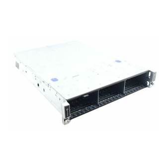
Page 13: Figure 2. 12 X 3.5" Drive Jbod 2000 Product Drawing
Intel® Storage Server System JBOD 2000 Family Hardware Guide Product Family Overview Figure 2. 12 x 3.5” Drive JBOD 2000 Product Drawing Revision 1.42... -
Page 14: Chassis Dimensions
Product Family Overview Intel® Storage Server System JBOD 2000 Family Hardware Guide Chassis Dimensions Figure 3. Chassis Dimensions Revision 1.42... -
Page 15: System Level Environmental Limits
Intel® Storage Server System JBOD 2000 Family Hardware Guide Product Family Overview System Level Environmental Limits To keep the system operating within supported maximum thermal limits, the system must meet the following operating and configuration guidelines: The system operating ambient is designed for sustained operation up to 35ºC (ASHRAE ... - Page 16 Intel Corporation server boards contain a number of high-density VLSI and power delivery components that need adequate airflow to cool. Intel ensures through its own chassis development and testing that when Intel server building blocks are used together, the fully integrated system will meet the intended thermal requirements of these components.
-
Page 17: System Features And Options Overview
Intel® Storage Server System JBOD 2000 Family Hardware Guide Product Family Overview System Features and Options Overview Figure 4. System Components Overview 2.3.1 Hot Swap Hard Drive Bay and Front Panel Options Figure 5. 12 x 3.5" Drive JBOD2000 Front View Figure 6. -
Page 18: Front Panel Options
Product Family Overview Intel® Storage Server System JBOD 2000 Family Hardware Guide 2.3.2 Front Panel Options Figure 7. Front Panel Options Label Description Power Button w/Integrated LED System Status LED The Power Button toggles the system power on and off. Pressing this button sends a signal to the integrated PDB board, which either powers on or powers off the system. - Page 19 Intel® Storage Server System JBOD 2000 Family Hardware Guide Product Family Overview Color State Criticality Description Amber Solid on SMBUS Alert P12V is out of its limits. Event P5V is out of its limits. Encountered A fan fault has been detected.
-
Page 20: Back Panel Features
Product Family Overview Intel® Storage Server System JBOD 2000 Family Hardware Guide 2.3.3 Back Panel Features Figure 8. Single-port Backplane JBOD2000 Back View Label Description SFF-8088 receptacle (label: A PRI) SFF-8088 receptacle (label: B PRI) Figure 9. Dual-port Backplane JBOD2000 Back View... -
Page 21: System Storage And Peripheral Drive Bays Overview
Intel® Storage Server System JBOD 2000 Family Hardware Guide System Storage and Peripheral Drive Bays Overview System Storage and Peripheral Drive Bays Overview The Intel ® Storage Server System JBOD2000 product family supports the following storage device options: Hot-swap 2.5” hard disk drives ... -
Page 22: Figure 12. Status And Activity Led On 2.5" Drive Tray
System Storage and Peripheral Drive Bays Overview Intel® Storage Server System JBOD 2000 Family Hardware Guide Light pipes integrated into the drive tray assembly direct the light emitted from Amber drive status and Green activity LEDs located next to each drive connector on the backplane, to the drive tray faceplate, making them visible from the front of the system. -
Page 23: 2.5" Drive Hot-Swap Backplane Overview
Intel® Storage Server System JBOD 2000 Family Hardware Guide System Storage and Peripheral Drive Bays Overview 3.1.1 2.5” Drive Hot-Swap Backplane Overview Depending on the number of hard disk drives supported by a given system SKU, a system can be configured with one, two, or three 8-drive backplanes. Each backplane is attached to the back of the drive bay assembly. -
Page 24: Cypress* Cy8C22545 Enclosure Management Controller
System Storage and Peripheral Drive Bays Overview Intel® Storage Server System JBOD 2000 Family Hardware Guide On the back side of each backplane are several connectors. The following illustration identifies each. Figure 15. Components on dual port 2.5” HSBP Label... -
Page 25: Hard Disk Drive Support
Intel® Storage Server System JBOD 2000 Family Hardware Guide System Storage and Peripheral Drive Bays Overview 3.5” Hard Disk Drive Support The server is available in 3.5” hard disk configurations of 12 drives as illustrated below. Figure 16. 3.5” Hard Drive Bay – 12-Drive Configuration The drive bay can support either SATA or SAS hard disk drives. -
Page 26: 3.5" Drive Hot-Swap Backplane Overview
System Storage and Peripheral Drive Bays Overview Intel® Storage Server System JBOD 2000 Family Hardware Guide Table 8. Activity LED Status Condition Drive Type Behavior Power on with no drive LED stays on. activity SATA LED stays off. Power on with drive LED blinks off when processing a command. -
Page 27: Cypress* Cy8C22545 Enclosure Management Controller
Intel® Storage Server System JBOD 2000 Family Hardware Guide System Storage and Peripheral Drive Bays Overview On the back side of each backplane are several connectors. The following illustration identifies each. Figure 21. Components on 3.5” HSBP Label Description 4-port mini-SAS connectors... -
Page 28: Power Subsystem
Power Subsystem Intel® Storage Server System JBOD 2000 Family Hardware Guide Power Subsystem This chapter provides a high-level overview of the power management features and ® specification data for the power supply options available for Intel Storage Server System JBOD 2000 Family. -
Page 29: Power Distribution Board (Pdb)
Intel® Storage Server System JBOD 2000 Family Hardware Guide Power Subsystem Power Distribution Board (PDB) Figure 23. Power Distribution Board (PDB) Revision 1.42... -
Page 30: Figure 24. Pdb Component Placement
Power Subsystem Intel® Storage Server System JBOD 2000 Family Hardware Guide Figure 24. PDB Component Placement Label Description Label Description HSBP power header 2x15-pin storage mini front panel header Expander SES-2 header 2x12-pin front panel header Expander power header 1x5 aux header... - Page 31 Storage Server System JBOD 2000 Family. The SAS expander in the Intel ® Storage System JBOD 2000 Family uses a firmware that programs the thermal controller when the system is turned on. If the SAS expander is not plugged into the PDB using the I C cable, the fans will run at 100% and the thermal controller will not be programmed correctly.
-
Page 32: Figure 25. Fan Fault Led Block Diagram
Power Subsystem Intel® Storage Server System JBOD 2000 Family Hardware Guide Interrupt Register 2 for ADT7476 (Bits 2, 3, and 4 used for fan faults): Figure 25. Fan Fault LED Block Diagram Revision 1.42... -
Page 33: Mechanical Overview
Intel® Storage Server System JBOD 2000 Family Hardware Guide Power Subsystem Mechanical Overview The physical size of the power supply enclosure is 39/40mm x 74mm x 185mm. The power supply contains a single 40mm fan. The power supply has a card edge output that interfaces with a 2x25 card edge connector in the system. -
Page 34: Power Connectors
Power Subsystem Intel® Storage Server System JBOD 2000 Family Hardware Guide Power Connectors 4.3.1 Power Supply Module Card Edge Connector Each power supply module has a single 2x25 card edge output connection that plugs directly into a matching slot connector on the server board. The connector provides both power and communication signals to the server board. -
Page 35: Hot-Swap Backplane Power Connector
Intel® Storage Server System JBOD 2000 Family Hardware Guide Power Subsystem 4.3.2 Hot-Swap Backplane Power Connector The JDOB’s PDB board includes four white 2x4-pin power connectors, used to provide power to the hot-swap backplanes. On the JBOD PDB, this connector is labeled as “HSBP PWR”. The following table provides the pin-out for this connector. -
Page 36: Ac Input Specifications
Power Subsystem Intel® Storage Server System JBOD 2000 Family Hardware Guide AC Input Specifications 4.6.1 Power Factor The power supply meets the power factor requirements stated in the Energy Star Program Requirements for Computer Servers. These requirements are stated below. -
Page 37: Ac Line Fuse
Intel® Storage Server System JBOD 2000 Family Hardware Guide Power Subsystem Table 15. AC Line Dropout/Holdup Loading Holdup Time 12msec 4.6.4.1 AC Line 12VSB Holdup The 12VSB output voltage stays in regulation under its full load (static or dynamic) during an AC dropout of 70ms min (=12VSB holdup time) whether the power supply is in ON or OFF state (PSON asserted or de-asserted). -
Page 38: Susceptibility Requirements
The power supply meets the following electrical immunity requirements when connected to a cage with an external EMI filter that meets the criteria defined in the SSI document EPS Power Supply Specification. For further information on Intel standards, request a copy of the Intel Environmental Standards Handbook. -
Page 39: Voltage Interruptions
Intel® Storage Server System JBOD 2000 Family Hardware Guide Power Subsystem The pass criteria include: no unsafe operation is allowed under any condition; all power supply output voltage levels to stay within proper spec levels; no change in operating state or loss of data during and after the test profile;... -
Page 40: Over Temperature Protection (Otp)
Power Subsystem Intel® Storage Server System JBOD 2000 Family Hardware Guide Table 20. Over Voltage Protection (OVP) Limits Output Voltage Min (V) Max (V) +12V 13.3 14.5 12VSB 13.3 14.5 4.6.17 Over Temperature Protection (OTP) The power supply is protected against over temperature conditions caused by loss of fan cooling or excessive ambient temperature. -
Page 41: Power Supply Status Led
Intel® Storage Server System JBOD 2000 Family Hardware Guide Power Subsystem Power Supply Status LED There is a single bi-color LED to indicate power supply status. The LED operation is defined in the following table. Table 21. LED Indicators Power Supply Condition... -
Page 42: Thermal Management
Thermal Management The Intel ® Storage Server System JBOD 2000 Family is designed to operate at external ambient temperatures of between 10ºC and 35ºC with limited excursion-based operation up to 45ºC and limited performance impact. Working with integrated platform management, several... -
Page 43: Thermal Sensor Input For Fan Speed Control
Each fan is designed for tool-less insertion and extraction from the fan assembly. For ® instructions on installing or removing a fan module, see the Intel JBOD 2000 Family Service Guide. Fan speed for each fan is controlled by integrated platform management controlled by ... -
Page 44: Power Supply Module Fan
Thermal Management Intel® Storage Server System JBOD 2000 Family Hardware Guide Each fan has a 10-pin wire harness that connects to a matching connector on the PDB. Figure 31. System Fan Assembly Table 22. System Fan Connector Pin-out SYS_FAN 1... -
Page 45: Jbod 2000 Internal Connection Overview
Allows multiple initiators to address a single target (in a fail-over configuration) All JBOD SKUs use the 36-port SAS expander card. Single-port JBOD 2000 SKU has one 36- port SAS expander card; dual-port JBOD 2000 SKU has two 36-port expander cards. -
Page 46: Figure 32. Internal Sas Expander Location
JBOD 2000 Internal Connection Overview Intel® Storage Server System JBOD 2000 Family Hardware Guide Figure 32. Internal SAS Expander Location Revision 1.42... -
Page 47: Jbod Sas Interface Board
JBOD 2000 Internal Connection Overview JBOD SAS Interface Board ® The JBOD SAS interface board is an independent product – Intel 8087-8088 Cable Connector Converter AXXSAS88CNVRT converts two internal SFF8087 x4 mini-SAS connectors to two external SFF8088 SAS x4 connectors. The 8x ports of 6Gb SAS can be supported with this adapter. -
Page 48: Pin-Outs
JBOD 2000 Internal Connection Overview Intel® Storage Server System JBOD 2000 Family Hardware Guide Pin-outs See the SAS Gen2 specification for correct pin-out for the SAS internal and external connectors. The connection between the internal mini-SAS and external mini-SAS needs to be one-to-one direct connection of differential pairs with length matching on the board. -
Page 49: Jbod2312S2Sp Interconnection
Intel® Storage Server System JBOD 2000 Family Hardware Guide JBOD 2000 Internal Connection Overview 6.3.1 JBOD2312S2SP Interconnection The Intel ® Storage Server System JBOD2312S2SP has a 12x3.5” single-port HSBP, a primary SAS expander, a dual-port SAS interface board, a PDB, a PSU, and three fans in its chassis. -
Page 50: Figure 35. Primary Sas Expander
JBOD 2000 Internal Connection Overview Intel® Storage Server System JBOD 2000 Family Hardware Guide Table 24. 12x3.5” Single-port JBOD 2000 Internal Components Label Description Label Description Front Panel Front Panel Cable HSBP Power Daisy Chain Cable Three 60mm System Fans... -
Page 51: Table 25. Primary Sas Expander In 12X3.5" Single-Port Jbod 2000 Connector Mapping
Intel® Storage Server System JBOD 2000 Family Hardware Guide JBOD 2000 Internal Connection Overview Table 25. Primary SAS Expander in 12x3.5” Single-port JBOD 2000 Connector Mapping Primary Interconnection SAS Expander Label Port 0 To Backplane Port 0 Port 1 To Backplane Port 1... -
Page 52: Jbod2224S2Dp Interconnection
JBOD 2000 Internal Connection Overview Intel® Storage Server System JBOD 2000 Family Hardware Guide 6.3.2 JBOD2224S2DP Interconnection The Intel ® Storage Server System JBOD2224S2DP has three 8x2.5” dual-port HSBPs, two SAS expanders, three dual-port SAS interface boards, a PDB, two PSUs, and three fans in its chassis. -
Page 53: Table 26. 2U 24X2.5" Dual-Port Jbod2000 Components
Intel® Storage Server System JBOD 2000 Family Hardware Guide JBOD 2000 Internal Connection Overview Table 26. 2U 24x2.5” Dual-port JBOD2000 Components Label Description Label Description Front Panel Front Panel Cable HSBP Power Daisy Chain Cable Three 60mm System Fans 2x15-pin Front Panel Connector on PDB... -
Page 54: Figure 37. Secondary Sas Expander
JBOD 2000 Internal Connection Overview Intel® Storage Server System JBOD 2000 Family Hardware Guide Figure 37. Secondary SAS Expander Table 27. Primary SAS Expander in 24x2.5” Dual-port JBOD 2000 Connector Mapping Primary Interconnection SAS Expander Label Port 0 To Backplane Port 0A... -
Page 55: Jbod 2000 External Sas Connection Mode Overview
Intel® Storage Server System JBOD 2000 Family Hardware Guide JBOD 2000 External SAS Connection Mode Overview JBOD 2000 External SAS Connection Mode Overview The Intel ® Storage Server System JBOD 2000 Family supports connection to many different external SAS HBA and SAS RAID controller solutions, to achieve single JBOD connection, multiple JBODs daisy chain connection, and failover connections. -
Page 56: Hard Drive Type
2400MB/s with SAS 2.0 technology. In the figure, the “4\” notation indicates a 4- lane bundled path. Either A PRI or B PRI SAS port on JBOD 2000 can be connected in this scenario. SATA or SAS hard drive can be supported. -
Page 57: Two Jbod 2000 Cascade
Figure 40 shows two cascaded single-port JBOD 2000 connecting to the SAS HBA or RAID adapter with one mini-SAS cable. The function of SAS port “A PRI” and “B PRI” on JBOD 2000 are equivalent. Either “A PRI” or “B PRI” SAS port can be connected to the SAS adapter or cascaded with other JBOD2000 in this scenario. -
Page 58: Dual-Path Connection
“B PRI” SAS port, and a controller connects to each “A PRI” SAS port with two mini-SAS cables. Any mini-SAS cable failure will not stop the data transfer between the host and two JBOD 2000. Both SAS and SATA drives support this configuration. -
Page 59: Dual-Port Jbod 2000 External Connection Mode
SAS controllers connecting to the dual-port JBOD2000. The connectors of the first controller connect to “A PRI” and “A SEC” port on JBOD 2000 with two mini-SAS cables. The connectors of the second controller connect to “B PRI” and “B SEC” port on JBOD2 000 with other two mini-SAS cables. -
Page 60: Dual-Domain Sas For Cascaded Dual-Port Jbod 2000
This dual-domain SAS architecture provides redundant pathways for two cascaded dual-port JBOD 2000 as in Figure 46. The “C PRI” ports on two JBOD 2000 are connected with one mini- SAS cable, and the “C SEC” ports are connected with another mini-SAS cable (see the red lines in Figure 46). -
Page 61: Dual-Domain Sas For Two-Node Cluster
SEC” port on JBOD 2000 with two mini-SAS cables, and the connectors of the SAS controller in the second server connect to “B PRI” and “B SEC” port on JBOD 2000 with other two mini-SAS cables. The cluster interconnect provides redundancy in the event of HBA or cable failure. Dual- domain SAS requires active/active configurations that permit both controllers to process IO transfers. -
Page 62: Figure 48. Cascaded Jbod 2000 For A Two-Node Cluster
JBOD 2000 External SAS Connection Mode Overview Intel® Storage Server System JBOD 2000 Family Hardware Guide Figure 48. Cascaded JBOD 2000 for a Two-node Cluster Note: Failover cluster usually needs special firmware and driver for SAS RAID adapter. Refer to ®... -
Page 63: Reference Documents
Intel® Storage Server System JBOD 2000 Family Hardware Guide Reference Documents Reference Documents Refer to the following documents for additional information: ® Intel Storage Server System JBOD 2000 Family Service Guide ® Intel High Availability Storage User Guide ...
Need help?
Do you have a question about the JBOD 2000 and is the answer not in the manual?
Questions and answers