
Related Manuals for Intel R1304BTSSFAN


Summary of Contents for Intel R1304BTSSFAN
- Page 1 ® Intel Server System R1304BTSSFAN/R1304BTLSFAN/ R1304BTLSHBN Service Guide ® A Guide for Technically Qualified Assemblers of Intel Identified Subassemblies/Products Intel Order Number G21355-003...
- Page 2 ® Information in this document is provided in connection with Intel products. No license, express or implied, by ® estoppel or otherwise, to any intellectual property rights is granted by this document. Except as provided in Intel ’s ® ®...
-
Page 3: Safety Information
Safety Information Important Safety Instructions Read all caution and safety statements in this document before performing any of the instructions. See also Intel Server Boards and Server Chassis Safety Information on the ® Intel Server Deployment Toolkit CD and/or at http://www.intel.com/support/... - Page 4 ® Intel Server System R1304BTSSFAN/R1304BTLSFAN/R1304BTLSHBN Service Guide...
-
Page 5: Warnings
Take care to grip with, but not squeeze, the pliers or other tool you use to remove a jumper, or you may bend or break the pins on the board. ® Intel Server System R1304BTSSFAN/R1304BTLSFAN/R1304BTLSHBN Service Guide... - Page 6 ® Intel Server System R1304BTSSFAN/R1304BTLSFAN/R1304BTLSHBN Service Guide...
-
Page 7: Preface
This includes how to navigate through the BIOS Setup screens, perform a BIOS update, and reset the password or CMOS. Information about the ® specific BIOS settings and screens is available in the Intel Server Board S1200BT Technical Product Specification. -
Page 8: Product Contents
S1200BTS. The Intel Server System R1304BTLSFAN/R1304BTLSHBN ships with the ® Intel Server Board S1200BTL. ® There are three versions of this server system: the Intel Server System R1304BTSSFAN, ® ® Intel Server System R1304BTLSFAN and the Intel Server System R1304BTLSHBN. - Page 9 — Four SATA cables for SATA HDDs — One front panel USB cable, installed in the server system — One front panel cable, installed in the server system • Documentation, drivers, and installation CD ® Intel Server System R1304BTSSFAN/R1304BTLSFAN/R1304BTLSHBN Service Guide...
-
Page 10: Intel ® Server System R1304Btlshbn Contents
— One front panel cable, installed in the server system — One SPGIO cable, installed in the server system — One I2C cable, installed in the server system • Documentation, drivers, and installation CD ® Intel Server System R1304BTSSFAN/R1304BTLSFAN/R1304BTLSHBN Service Guide... -
Page 11: Server System References
Accessories or other Intel Spares/Parts List & Configuration Guide server products This is available from your Intel field representative or on the Server Configurator Tool at: http://serverconfigurator.intel.com/default.aspx Hardware (peripheral For the Tested Hardware Operating Systems List, you can go to the ®... - Page 12 ® Intel Server System R1304BTSSFAN/R1304BTLSFAN/R1304BTLSHBN Service Guide...
-
Page 13: Table Of Contents
Warnings ..........................v Preface ........................vii About this Manual ........................ vii Manual Organization ......................vii Product Contents .........................viii ® Intel Server System R1304BTSSFAN Contents ............viii ® Intel Server System R1304BTLSFAN Contents ............viii ® Intel Server System R1304BTLSHBN Contents ............x Server System References .................... - Page 14 Removing the Heat Sink and Processor ..............35 Installing the Processor ....................36 Installing the Heat Sink ....................39 Installing and Removing a Hard Drive (R1304BTSSFAN/R1304BTLSFAN) ...... 41 Installing a Hard Disk Drive (R1304BTSSFAN/R1304BTLSFAN) ......41 Removing a Hard Disk Drive (R1304BTSSFAN/R1304BTLSFAN) ......43 Installing and Removing a Hot-Swap SATA Drive (R1304BTLSHBN) ........
- Page 15 Problems with Application Software that Ran Correctly Earlier ....................82 Devices are not Recognized under Device Manager (Microsoft Windows* Operating Sys- tem) ........................83 Hard Drive(s) are not Recognized ................83 Bootable CD-ROM Disk Is Not Detected ..............83 ® Intel Server System R1304BTSSFAN/R1304BTLSFAN/R1304BTLSHBN Service Guide...
- Page 16 BIOS POST Beep Codes .................... 84 Appendix C: Warranty ....................85 ® Limited Warranty for Intel Chassis Subassembly Products ..........85 Appendix D: Getting Help ..................89 World Wide Web ......................... 89 Telephone ........................... 89 ® Intel Server System R1304BTSSFAN/R1304BTLSFAN/R1304BTLSHBN Service Guide...
- Page 17 Figure 21. Installing the Heat Sink ..................39 Figure 22. Removing Drive Carrier from the Server System (R1304BTLSFAN)..... 42 Figure 23. Installing Drive into Drive Carrier (R1304BTSSFAN/R1304BTLSFAN) ....42 Figure 24. Removing the Drive Carrier (R1304BTLSHBN) ............. 44 Figure 25. Installing Drive into Drive Carrier (R1304BTLSHBN)..........45 Figure 26.
- Page 18 Figure 43. Cable Routing (R1304BTLSHBN) ................. 72 ® xviii Intel Server System R1304BTSSFAN/R1304BTLSFAN/R1304BTLSHBN Service Guide...
-
Page 19: List Of Tables
Table 5. Setup Menu Key Use ....................20 Table 6. Power Supply Output Capability ................73 Table 7. System Environmental Specifications ...............74 Table 8. Resetting the System ....................75 Table 9. LED Information ......................84 Table 10. POST Error Beep Codes ..................84 ® Intel Server System R1304BTSSFAN/R1304BTLSFAN/R1304BTLSHBN Service Guide... - Page 20 ® Intel Server System R1304BTSSFAN/R1304BTLSFAN/R1304BTLSHBN Service Guide...
-
Page 21: Chapter 1: Server System Features
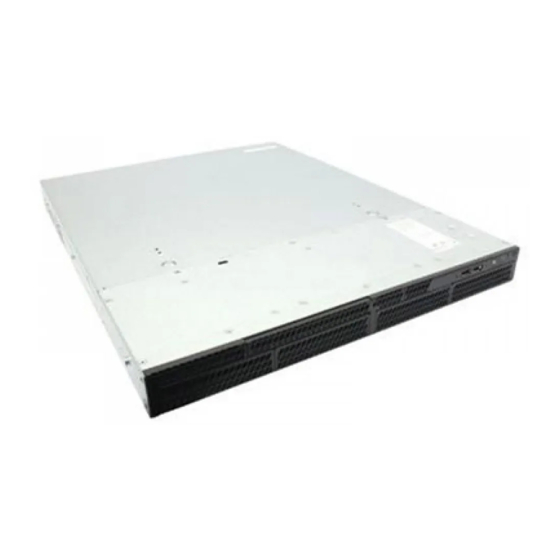
Figure 1. Intel Server System R1304BTSSFAN/R1304BTLSFAN Note: Figure 1 is shown without an optional optical drive installed. ® Figure 2. Intel Server System R1304BTLSHBN Note: Figure 2 is shown with an optional optical drive installed. ® Intel Server System R1304BTSSFAN/R1304BTLSFAN/R1304BTLSHBN Service Guide... -
Page 22: Table 1. Intel ® Server System R1304Btssfan/R1304Btlsfan/R1304Btlshbn Feature Summary
Four USB 2.0 connectors • Two USB 2.0 connectors (front) Expansion Capabilities One low-profile riser slot supporting one low-profile half-length PCI Express* 2.0 x8 add-in card. (optional accessory required) Fans Supports three system fans. ® Intel Server System R1304BTSSFAN/R1304BTLSFAN/R1304BTLSHBN Service Guide... - Page 23 Integrated Baseboard Management Controller (Integrated BMC), IPMI 2.0 compliant • Integrated 2D video controller on PCI-E x 1 • ® Optional Intel Remote Management Module 4 (RMM4) lite and optional dedicated NIC module ® Intel Server System R1304BTSSFAN/R1304BTLSFAN/R1304BTLSHBN Service Guide...
-
Page 24: Chassis Component Identification
System Front Panel The front of the server system includes the following buttons and LEDs. ® Note: The LAN3/4 LEDs are not used on the Intel Server Systems R1304BTSSFAN/ R1304BTLSFAN or R1304BTLSHBN. Unstuffable ID Button with ID LED and Status/ ®... - Page 25 LAN link/no access. ® (LAN 1-2 for Intel Green Blink LAN access. Server Board S1200BT) Idle. Chassis Identification Blue Front panel chassis ID button pressed. Blue Blink Unit selected for identification via software. No identification. ® Intel Server System R1304BTSSFAN/R1304BTLSFAN/R1304BTLSHBN Service Guide...
-
Page 26: System Rear
LAN link is not established. LAN link is established. Blinking LAN activity is occurring. Right 10 Mbit/sec data rate is selected Green 100 Mbit/sec data is selected Yellow 1000 Mbit/sec data rate is selected ® Intel Server System R1304BTSSFAN/R1304BTLSFAN/R1304BTLSHBN Service Guide... -
Page 27: Peripheral Devices (R1304Btssfan/R1304Btlsfan)
One slimline drive carrier is included with your server system; you must purchase the optical drive separately. To use the slimline DVD drive provided by Intel, use order code AXXSATADVDROM. To use the slimline DVD CDRW drive provided by Intel, use order code AXXSATADVDRWROM. -
Page 28: Internal Components (R1304Btssfan)
Rack Handles (two) System Memory DIMM Sockets Server Board Cooling Fans PCIe* Riser Assembly Front Panel Processor and Heatsink Hard Drive Bays Power Supply Front Panel Slimline Optical Drive Figure 5. System Components (R1304BTSSFAN) ® Intel Server System R1304BTSSFAN/R1304BTLSFAN/R1304BTLSHBN Service Guide... -
Page 29: Internal Components (R1304Btlsfan)
Rack Handles (two) System Memory DIMM Sockets Server Board Cooling Fans PCIe* Riser Assembly Front Panel Processor and Heatsink Hard Drive Bays Power Supply Front Panel Slimline Optical Drive Figure 6. System Components (R1304BTLSFAN) ® Intel Server System R1304BTSSFAN/R1304BTLSFAN/R1304BTLSHBN Service Guide... -
Page 30: Internal Components (R1304Btlshbn)
Rack Handles (two) System Memory DIMM Slots Server Board Cooling Fans PCIe* Riser Assembly Front Panel Board Processor and Heatsink Hard Drive Bays Power Supply Slimline Optical Drive Figure 7. System Components (R1304BTLSHBN) ® Intel Server System R1304BTSSFAN/R1304BTLSFAN/R1304BTLSHBN Service Guide... -
Page 31: Server Board Connectors/Components (S1200Bts)
Slot 7, PCI Express* Gen2 x8 (x16 Chassis Intrusion connector) Ethernet and Dual USB COMBO SATA_SGPIO Ethernet and Dual USB COMBO SYS_FAN_3 Video port Six 3Gb/s SATA ports External Serial port Internal USB connector CPU Power connector Internal USB ® Intel Server System R1304BTSSFAN/R1304BTLSFAN/R1304BTLSHBN Service Guide... -
Page 32: Server Board Connectors/Components (S1200Btl)
MAIN power connector HDD LED M. TPM connector ® Figure 8. Intel Server Board S1200BTS Layout Server Board Connectors/Components (S1200BTL) Slot 1, 32 Mbit/33 MHz PCI System FAN2 and System FAN3 Connector CPU connector ® Intel Server System R1304BTSSFAN/R1304BTLSFAN/R1304BTLSHBN Service Guide... -
Page 33: Figure 9. Intel ® Server Board S1200Btl Layout
Internal USB Connector RMM4 Dedicated NIC connector CMOS battery Four DIMM Slots Four 3Gb/s SATA ports P/S AUX Two 6Gb/s SATA ports MAIN POWER Smart module ® Figure 9. Intel Server Board S1200BTL Layout ® Intel Server System R1304BTSSFAN/R1304BTLSFAN/R1304BTLSHBN Service Guide... -
Page 34: Configuration Jumpers
Configuration Jumpers BIOS Default Recovery Enabled J2G1 Password Default Clear Cleared J1G1 Protected Default Clear J1H3 Default Force Update Enabled J2J1 AF003618 Figure 10. Configuration Jumper Locations (S1200BTS) Figure 11. Configuration Jumper Locations ® Intel Server System R1304BTSSFAN/R1304BTLSFAN/R1304BTLSHBN Service Guide... - Page 35 Jumper in normal position (pins 1-2) allows normal system operation with correct BIOS settings. System will POST normally. ® Jumper in maintenance mode (pins 2-3) allows Intel AMT setting/ password reset. Jumper removed is used to recover from a corrupted BIOS. Bootable media with a valid BIOS ROM required.
-
Page 36: Hardware Requirements
B1 Dual Channel B2 Dual Channel 3 DIMMs Intel Symmetric Symmetric Asymmetric Flex Memory A1 Dual Channel A2 Dual Channel B1 Dual Channel B2 Dual Channel 4 DIMMs Dual Symmetric Symmetric Symmetric Symmetric Channel Symmetric ® Intel Server System R1304BTSSFAN/R1304BTLSFAN/R1304BTLSHBN Service Guide... - Page 37 E3-1200 based platforms. All three channels may be populated in any order and have no matching requirements. All channels must run at the same interface frequency, but individual channels may run at different DIMM timings (RAS latency, CAS latency, and so on). ® Intel Server System R1304BTSSFAN/R1304BTLSFAN/R1304BTLSHBN Service Guide...
- Page 38 ® Intel Server System R1304BTSSFAN/R1304BTLSFAN/R1304BTLSHBN Service Guide...
-
Page 39: Chapter 2: Server Utilities
You can run BIOS Setup with or without an operating system ® present. See the links under “Server System References” on page xi for a link to the Intel Server Board S1200BT Technical Product Specification where you will find details about specific BIOS setup screens. Starting Setup You can enter and start BIOS Setup under several conditions: •... -
Page 40: Table 5. Setup Menu Key Use
If “No” is selected and <Enter> is pressed, or <Esc> is pressed, the user is returned to where they were before <F9> was pressed without affecting any existing field values. ® Intel Server System R1304BTSSFAN/R1304BTLSFAN/R1304BTLSHBN Service Guide... -
Page 41: Upgrading The Bios
Press <F2> Key if you want to run SETUP 2. Write down the current settings in the BIOS Setup program. Note: Do not skip Step 2. You need these settings to configure your server at the end of the procedure. ® Intel Server System R1304BTSSFAN/R1304BTLSFAN/R1304BTLSHBN Service Guide... -
Page 42: Upgrading The Bios
1. Power down and unplug the system from the AC power source. 2. Move the recovery jumper from the default location at pins 1 and 2 to cover pins 2 and 3. For location of the jumper, see “Configuration Jumpers” on page ® Intel Server System R1304BTSSFAN/R1304BTLSFAN/R1304BTLSHBN Service Guide... -
Page 43: Clearing The Password
1 and 2. 7. Reconnect the AC power and power up the server. 8. Close the server chassis. The password is cleared and can be reset by going into the BIOS setup. ® Intel Server System R1304BTSSFAN/R1304BTLSFAN/R1304BTLSHBN Service Guide... -
Page 44: Clearing The Cmos
6. Perform the Integrated BMC firmware update procedure as documented in the README.TXT file included in the given Integrated BMC firmware update package. After successful completion of the firmware update process, the firmware ® Intel Server System R1304BTSSFAN/R1304BTLSFAN/R1304BTLSHBN Service Guide... -
Page 45: Updating Me Firmware
9. Move jumper from the enabled position (covering pins 2 and 3) to the disabled position (covering pins 1 and 2). 10. Close the server chassis. 11. Reconnect the AC cord and power up the server. ® Intel Server System R1304BTSSFAN/R1304BTLSFAN/R1304BTLSHBN Service Guide... - Page 46 ® Intel Server System R1304BTSSFAN/R1304BTLSFAN/R1304BTLSHBN Service Guide...
-
Page 47: Chapter 3: Hardware Installations And Upgrades
Server System R1304BTLSHBN are hot-swappable and are noted as such (where applicable) in the following instructions. ® Note: Most of the illustrations in this chapter show the Intel Server System R1304BTLSFAN with an optional optical drive installed. Unless otherwise noted, the instructions for ®... -
Page 48: Removing And Installing The Server Cover
5. Push down the two buttons, then push rearward. See letter "B" in Figure 15. Slide the cover back until it stops and then lift the cover upward to remove it. See letter “C” in Figure 12. AF003681 Figure 12. Removing the Server System Cover ® Intel Server System R1304BTSSFAN/R1304BTLSFAN/R1304BTLSHBN Service Guide... -
Page 49: Installing The Server System Cover
3. Install the screw at the front of the server. See letter “B” in Figure 13. Recessed Edge AF003703 Figure 13. Installing the Server System Cover 4. Reconnect all peripheral devices and the AC power cord. ® Intel Server System R1304BTSSFAN/R1304BTLSFAN/R1304BTLSHBN Service Guide... -
Page 50: Removing And Installing The Processor Air Duct
2. Power down the server and unplug all peripheral devices and the AC power cable. 3. Remove the server system cover. For instructions, see “Removing the Server System Cover” on page 4. Lift the processor air duct from its location. ® Intel Server System R1304BTSSFAN/R1304BTLSFAN/R1304BTLSHBN Service Guide... -
Page 51: Installing The Processor Air Duct
5. Install the server system cover. For instructions, see “Installing the Server System Cover” on page AF003701 Figure 14. Installing the Processor Air Duct ® Intel Server System R1304BTSSFAN/R1304BTLSFAN/R1304BTLSHBN Service Guide... -
Page 52: Installing And Removing Memory
DIMM B2 starting from the center of the board. See “Memory” on page 16 for a discussion of the memory requirements and options. See “Server System References” on page xi for a link to the list of tested DIMMs. ® Intel Server System R1304BTSSFAN/R1304BTLSFAN/R1304BTLSHBN Service Guide... -
Page 53: Installing Dimms
“Installing the Server System Cover” on page Removing DIMMs To remove a DIMM, follow these steps: 1. Observe the safety and ESD precautions at the beginning of this book. See “Safety Information” on page iii. ® Intel Server System R1304BTSSFAN/R1304BTLSFAN/R1304BTLSHBN Service Guide... - Page 54 6. Holding the DIMM by the edges, lift it from the socket, and store it in an anti-static package. 7. Install the server system cover. For instructions, see “Installing the Server System Cover” on page ® Intel Server System R1304BTSSFAN/R1304BTLSFAN/R1304BTLSHBN Service Guide...
-
Page 55: Replacing The Processor
9. Remove the processor. 10. If installing a replacement processor, see “Installing the Processor” on page Otherwise, install the protective socket cover over the empty processor socket and then reinstall the chassis cover. ® Intel Server System R1304BTSSFAN/R1304BTLSFAN/R1304BTLSHBN Service Guide... -
Page 56: Installing The Processor
Figure 16. Lifting the Processor Socket Handle 5. Push the rear tab with your finger to slightly lift the front of the load plate. Raise the load plate completely. Raise the CPU load plate (see Figure 17). ® Intel Server System R1304BTSSFAN/R1304BTLSFAN/R1304BTLSHBN Service Guide... -
Page 57: Figure 17. Opening The Load Plate
Caution: Do not touch the socket pins; they are very sensitive and easily damaged. 6. Remove the processor from the packaging box and remove the protective shipping cover. See Figure AF003189 Figure 18. Removing the Shipping Cover ® Intel Server System R1304BTSSFAN/R1304BTLSFAN/R1304BTLSHBN Service Guide... -
Page 58: Figure 19. Installing The Processor
Note: Retain the protective socket cover for use when removing a processor that will not be replaced. 10. Lower the CPU load plate. 11. Lower the socket lever. 12. Install the heat sink. For instructions, see “Installing the Heat Sink” on page ® Intel Server System R1304BTSSFAN/R1304BTLSFAN/R1304BTLSHBN Service Guide... -
Page 59: Installing The Heat Sink
5. Gradually and equally tighten each captive screw in the same order until each is firmly tightened. AF001049 Figure 21. Installing the Heat Sink 6. Reinstall and reconnect any parts you removed or disconnected to reach the processor sockets. ® Intel Server System R1304BTSSFAN/R1304BTLSFAN/R1304BTLSHBN Service Guide... - Page 60 7. Install the server system cover. For instructions, see “Installing the Server System Cover” on page ® Intel Server System R1304BTSSFAN/R1304BTLSFAN/R1304BTLSHBN Service Guide...
-
Page 61: Installing And Removing A Hard Drive (R1304Btssfan/R1304Btlsfan)
Note: The server system does not support all hard drives. See “Server System References” on page xi for an Internet link to a list of supported hardware. Installing a Hard Disk Drive (R1304BTSSFAN/ R1304BTLSFAN) Note: If you are replacing a hard drive, see “Installing and Removing a Hard Drive (R1304BTSSFAN/R1304BTLSFAN)”... -
Page 62: Figure 22. Removing Drive Carrier From The Server System (R1304Btlsfan)
8. Attach the hard drive to the carrier with four screws as shown. 9. Re-install the hard drive/carrier assembly into the chassis. AF003686 Figure 23. Installing Drive into Drive Carrier (R1304BTSSFAN/ R1304BTLSFAN) 10. Secure the hard drive/carrier assembly with the screws. -
Page 63: Removing A Hard Disk Drive (R1304Btssfan/R1304Btlsfan)
Store the drive in an anti-static bag. 8. If you are installing a new drive, skip the rest of these steps and instead see “Installing and Removing a Hard Drive (R1304BTSSFAN/R1304BTLSFAN)” on page 41, beginning with step 7. -
Page 64: Installing And Removing A Hot-Swap Sata Drive (R1304Btlshbn)
Store the plastic retention device for future use. 6. Remove the hard drive from its wrapper and place it on an antistatic surface. 7. Set any jumpers and/or switches on the drive according to the drive manufacturer's instructions. ® Intel Server System R1304BTSSFAN/R1304BTLSFAN/R1304BTLSHBN Service Guide... -
Page 65: Figure 25. Installing Drive Into Drive Carrier (R1304Btlshbn)
11. When the black drive carrier lever begins to close by itself, push on it to lock the drive assembly into place (see letter “F” in Figure 26). ® Intel Server System R1304BTSSFAN/R1304BTLSFAN/R1304BTLSHBN Service Guide... -
Page 66: Removing A Hot-Swap Sata Drive (R1304Btlshbn)
7. With the black lever in the fully open position, slide the drive carrier into the server system. The green latch must be to the right. Do not push on the black lever until the lever begins to close by itself. ® Intel Server System R1304BTSSFAN/R1304BTLSFAN/R1304BTLSHBN Service Guide... - Page 67 9. Install the server system cover. For instructions, see “Installing the Server System Cover” on page 10. (Optional) Install the front bezel. 11. Plug all peripheral devices and the AC power cable into the server. ® Intel Server System R1304BTSSFAN/R1304BTLSFAN/R1304BTLSHBN Service Guide...
-
Page 68: Installing Or Removing A Slimline Optical Drive
3. Remove two screws secured the Filler Panel. 4. Remove the Filler Panel. AF003724 Figure 27. Removing the Knock-out from the Sheet Metal Panel 5. Attach the latch to the optical drive as shown, using two screws. ® Intel Server System R1304BTSSFAN/R1304BTLSFAN/R1304BTLSHBN Service Guide... -
Page 69: Figure 28. Attaching The Latch To The Optical Drive
Figure 29. Installing the Optical Drive into the System 10. Install the server system cover. For instructions, see “Installing the Server System Cover” on page 11. Plug all peripheral devices and the AC power cable into the server. ® Intel Server System R1304BTSSFAN/R1304BTLSFAN/R1304BTLSHBN Service Guide... -
Page 70: Removing A Slimline Optical Drive
7. If you are installing a replacement optical drive, skip the rest of these steps and instead continue with “Installing a Slimline Optical Drive” on page 48, Step 5 on page 48. 8. Install the server system cover. For instructions, see “Installing the Server System Cover” on page ® Intel Server System R1304BTSSFAN/R1304BTLSFAN/R1304BTLSHBN Service Guide... -
Page 71: Installing And Removing The Pcie* Riser Assembly
5. Lift riser assembly up to remove it. Use caution to gently ease the riser card from the add-in card slot so you do not damage the slot or the riser card. See Figure Riser Card Connector AF003683 Figure 30. Removing PCIe* Riser Assembly from the Server System ® Intel Server System R1304BTSSFAN/R1304BTLSFAN/R1304BTLSHBN Service Guide... -
Page 72: Installing The Pcie* Riser Assembly
4. Connect any cables to add-in cards that require them. See your add-in card documentation for information and add-in card requirements. 5. Install the server system cover. For instructions, see “Installing the Server System Cover” on page ® Intel Server System R1304BTSSFAN/R1304BTLSFAN/R1304BTLSHBN Service Guide... -
Page 73: Installing Or Replacing A Pcie* Riser Card
8. Install the replacement riser connector, if desired. For instructions, see “Installing a PCIe* Riser Card” on page 9. Install the PCIe* Riser assembly into the server system. For instructions, see “Installing the PCIe* Riser Assembly” on page ® Intel Server System R1304BTSSFAN/R1304BTLSFAN/R1304BTLSHBN Service Guide... -
Page 74: Installing A Pcie* Riser Card
“Installing the Processor Air Duct” on page 12. Install the server system cover. For instructions, see “Installing the Server System Cover” on page 13. Plug all peripheral devices and the AC power cable into the server. ® Intel Server System R1304BTSSFAN/R1304BTLSFAN/R1304BTLSHBN Service Guide... -
Page 75: Installing And Removing A Pci Add-In Card
See letter “C” in Figure 8. Re-install the screw you removed in Step 5. See letter “A” in Figure ® Intel Server System R1304BTSSFAN/R1304BTLSFAN/R1304BTLSHBN Service Guide... -
Page 76: Removing A Pci Add-In Card
7. Install a filler panel over the opening at the rear of the riser assembly. ® Intel Server System R1304BTSSFAN/R1304BTLSFAN/R1304BTLSHBN Service Guide... - Page 77 “Installing the Processor Air Duct” on page 11. Install the server system cover. For instructions, see “Installing the Server System Cover” on page 12. Plug all peripheral devices and the AC power cable into the server. ® Intel Server System R1304BTSSFAN/R1304BTLSFAN/R1304BTLSHBN Service Guide...
-
Page 78: Replacing The Server Board
8. Remove the DIMMs. For instructions, see “Removing DIMMs” on page 9. Remove the nine screws from the server board and lift the server board from the server system. AF003739 Figure 35. Removing the Server Board ® Intel Server System R1304BTSSFAN/R1304BTLSFAN/R1304BTLSHBN Service Guide... -
Page 79: Installing The Server Board
Riser Assembly” on page 6. Place the server board into the server system as shown by letter “A” in Figure 7. Attach the server board with nine screws. See letter “B” in Figure ® Intel Server System R1304BTSSFAN/R1304BTLSFAN/R1304BTLSHBN Service Guide... -
Page 80: Figure 36. Installing The Server Board
“Installing the Processor Air Duct” on page 14. Install the server system cover. For instructions, see “Installing the Server System Cover” on page 15. Plug all peripheral devices and the AC power cable into the server. ® Intel Server System R1304BTSSFAN/R1304BTLSFAN/R1304BTLSHBN Service Guide... -
Page 81: Replacing The Cmos Battery
System Cover” on page 4. Remove the server's cover and locate the battery. See Figure 5. Pull back gently on the metal tab at the top of the battery. 6. Remove the battery from its socket. ® Intel Server System R1304BTSSFAN/R1304BTLSFAN/R1304BTLSHBN Service Guide... -
Page 82: Figure 37. Replacing The Cmos Battery
8. Remove the new lithium battery from its package, and, being careful to observe the correct polarity, insert it in the battery socket. 9. Close the chassis. 10. Run the BIOS Setup utility to restore the configuration settings. ® Intel Server System R1304BTSSFAN/R1304BTLSFAN/R1304BTLSHBN Service Guide... -
Page 83: Replacing The Power Supply
9. Connect the power supply cables to the server board and peripherals. See Figure 10. Install the server system cover. For instructions, see “Installing the Server System Cover” on page 11. Plug all peripheral devices and the AC power cable into the server. ® Intel Server System R1304BTSSFAN/R1304BTLSFAN/R1304BTLSHBN Service Guide... -
Page 84: Replacing A System Fan
“Removing the Processor Air Duct” on page 5. Disconnect the fan cables from the server board. 6. Lift the fan holder from the server. AF003568 Figure 39. Removing Bracket and System Fans from Server System. ® Intel Server System R1304BTSSFAN/R1304BTLSFAN/R1304BTLSHBN Service Guide... - Page 85 11. Connect the fans to the server board. 12. Install the processor air duct. For instructions. see “Installing the Processor Air Duct” on page ® Intel Server System R1304BTSSFAN/R1304BTLSFAN/R1304BTLSHBN Service Guide...
-
Page 86: Installing And Removing The Rack Handles
Figure 40. Installing the Rack Handle 5. Repeat Step 4 on the opposite side of the server. 6. (Optional) Install the front bezel, if desired. 7. Plug all peripheral devices and the AC power cable into the server. ® Intel Server System R1304BTSSFAN/R1304BTLSFAN/R1304BTLSHBN Service Guide... -
Page 87: Removing The Rack Handles
5. Repeat Step 4 on the opposite side of the system. 6. (Optional) Install the front bezel, if desired. 7. Plug all peripheral devices and the AC power cable into the server. ® Intel Server System R1304BTSSFAN/R1304BTLSFAN/R1304BTLSHBN Service Guide... - Page 88 ® Intel Server System R1304BTSSFAN/R1304BTLSFAN/R1304BTLSHBN Service Guide...
-
Page 89: Appendix A: Technical Reference
For example, the PCI cooling fan cable is labeled with the letter “C” both where it connects to the server board and at the PCI cooling fan itself. ® Intel Server System R1304BTSSFAN/R1304BTLSFAN/R1304BTLSHBN Service Guide... -
Page 90: Cable Routing (R1304Btssfan)
Power Supply to CPU Power SATA port to HSBP HDD2 ODD to SATA Port SATA port to HSBP HDD3 M. Power Supply to ODD System FAN1 Power Supply to HDDs Figure 41. Cable Routing (R1304BTSSFAN) ® Intel Server System R1304BTSSFAN/R1304BTLSFAN/R1304BTLSHBN Service Guide... -
Page 91: Cable Routing (R1304Btlsfan)
Power Supply to CPU Power SATA port to HSBP HDD2 M. ODD to SATA Port SATA port to HSBP HDD3 Power Supply to ODD System FAN1 Power Supply to HDDs System FAN2 Figure 42. Cable Routing (R1304BTLSFAN) ® Intel Server System R1304BTSSFAN/R1304BTLSFAN/R1304BTLSHBN Service Guide... -
Page 92: Cable Routing (R1304Btlshbn)
Power Supply to ODD ODD to SATA Port Power Supply to HDDs M. SGPIO Internal USB to Front System FAN1 Front Panel System FAN2 SATA port to HSBP HDD0 System FAN3 Figure 43. Cable Routing (R1304BTLSHBN) ® Intel Server System R1304BTSSFAN/R1304BTLSFAN/R1304BTLSHBN Service Guide... -
Page 93: 350-W Single Power Supply Input Voltages
Warning: Do not exceed a combined power output of 90 W for the +5 V and +3.3 V outputs. Exceeding a combined 90 W will overload the power subsystem and may cause the power supplies to overheat and malfunction. ® Intel Server System R1304BTSSFAN/R1304BTLSFAN/R1304BTLSHBN Service Guide... -
Page 94: System Environmental Specifications
7 Bels in sound power for a typical office ambient temperature (65 to 75 °F). Your selection of peripherals may change the noise level. Electrostatic Tested to 8 Kilovotls (KV) contact discharge, 12 kilovolts (KV) air discharge; discharge (ESD) no component damage. ® Intel Server System R1304BTSSFAN/R1304BTLSFAN/R1304BTLSHBN Service Guide... -
Page 95: Appendix B: Troubleshooting
In addition to the server firmware and files, also update any drivers used for components you installed in your system, such as video drivers, network drivers, and SATA drivers. Intel provides a package called the “Platform Confidence Test” that may help with your diagnostics. See “Server System References” on page xi for a link to this software. -
Page 96: Problems Following Initial System Installation
Are all integrated components from the tested components lists? Check the tested memory and chassis lists, as well as the supported hardware and operating system list. See “Server System References” on page xi for links to the tested component lists. ® Intel Server System R1304BTSSFAN/R1304BTLSFAN/R1304BTLSHBN Service Guide... -
Page 97: Hardware Diagnostic Testing
“No Characters Appear on Screen” on page Specific Problems and Corrective Actions This section provides possible solutions for these specific problems: • Power light does not light. • No characters appear on screen. ® Intel Server System R1304BTSSFAN/R1304BTLSFAN/R1304BTLSHBN Service Guide... -
Page 98: Power Light Does Not Light
No Characters Appear on Screen Check the following: • Is the keyboard functioning? Test it by turning the “Num Lock” function on and off to make sure the Num Lock light is functioning. ® Intel Server System R1304BTSSFAN/R1304BTLSFAN/R1304BTLSHBN Service Guide... -
Page 99: Characters Are Distorted Or Incorrect
Does this video monitor work correctly if plugged into a different system? System Cooling Fans Do Not Rotate Properly If the system cooling fans are not operating properly, it is an indication of possible system component failure. ® Intel Server System R1304BTSSFAN/R1304BTLSFAN/R1304BTLSHBN Service Guide... -
Page 100: Drive Activity Light Does Not Light
• Try a different network cable. • Make sure you are using the correct and the current drivers. See “Server System References” on page xi for a link to the current drivers. ® Intel Server System R1304BTSSFAN/R1304BTLSFAN/R1304BTLSHBN Service Guide... -
Page 101: Problems With Network
Try reseating the add-in adapter. The add-in adapter stopped working without apparent cause • Reseat the adapter. • The network driver files may be corrupt or deleted. Delete and then reinstall the drivers. • Run diagnostics. ® Intel Server System R1304BTSSFAN/R1304BTLSFAN/R1304BTLSHBN Service Guide... -
Page 102: System Boots When Installing Pci Card
• If you suspect a transient voltage spike, power outage, or brownout might have occurred, reload the software and try running it again. Symptoms of voltage spikes ® Intel Server System R1304BTSSFAN/R1304BTLSFAN/R1304BTLSHBN Service Guide... -
Page 103: Devices Are Not Recognized Under Device Manager (Microsoft Windows* Operating System)
Devices are not Recognized under Device Manager (Microsoft Windows* Operating System) ® The Microsoft Windows* operating systems do not include all of the drivers for the Intel chipsets, onboard NICs, and other components. See “Server System References” on page xi for a link to the current drivers and chipset files. -
Page 104: Led Information
BIOS beep codes. Table 10. POST Error Beep Codes Number of Reason for Beeps and Action to Take Beeps System halted because a fatal error related to the memory was detected. ® Intel Server System R1304BTSSFAN/R1304BTLSFAN/R1304BTLSHBN Service Guide... -
Page 105: Appendix C: Warranty
"as is" unless specifically provided for otherwise in any software license accompanying the software. If any Product furnished by Intel which is the subject of this Limited Warranty fails during the warranty period for reasons covered by this Limited Warranty, Intel, at its option, will: •... -
Page 106: Warranty Limitations And Exclusions
Limitations of Liability Intel's responsibility under this, or any other warranty, implied or expressed, is limited to repair, replacement, or refund, as set forth above. These remedies are the sole and exclusive remedies for any breach of warranty. -
Page 107: How To Obtain Warranty Service
Telephone Support If you cannot find the information you need on Intel's World Wide Web site (http:// www.intel.com/), call your local distributor or an Intel Customer Support representative. - Page 108 ® Intel Server System R1304BTSSFAN/R1304BTLSFAN/R1304BTLSHBN Service Guide...
-
Page 109: Appendix D: Getting Help
Telephone All calls are billed per incident, levied in local currency at the applicable credit card exchange rate plus applicable taxes. (Intel reserves the right to change the pricing for telephone support at any time without notice). ® Before calling, fill out an Intel Server Issue Report Form. -
Page 110: Latin America
Easter Island....Contact AT&T USA at 800 800 311. Once connected, dial 800 843 4481 Mainland and Juan .. Contact AT&T USA at 800 225 288. Once connected, dial 800 843 4481 ® Intel Server System R1304BTSSFAN/R1304BTLSFAN/R1304BTLSHBN Service Guide... - Page 111 Panama..Contact AT&T USA at 00 800 001 0109. Once connected, dial 800 843 4481 Paraguay ... 001 916 377 0114 Peru ... 001 916 377 0114 Uruguay..001 916 377 0114 Venezuela... Contact AT&T USA at 0 800 2255 288. Once connected, dial 800 843 4481 ® Intel Server System R1304BTSSFAN/R1304BTLSFAN/R1304BTLSHBN Service Guide...
- Page 112 ® Intel Server System R1304BTSSFAN/R1304BTLSFAN/R1304BTLSHBN Service Guide...
Need help?
Do you have a question about the R1304BTSSFAN and is the answer not in the manual?
Questions and answers