Table of Contents
Advertisement
Quick Links
Advertisement
Table of Contents

Subscribe to Our Youtube Channel
Related Manuals for Silca Fastbit


Summary of Contents for Silca Fastbit
- Page 1 Fastbit Operating Manual Original Instructions D444087XA vers. 1.0...
- Page 2 This manual has been drawn up by SILCA S.p.A. All rights reserved. No part of this publication may be reproduced or used in any form or by any means (photocopying, microfi lm or other) without the written permission of SILCA S.p.A. Edition: October 2014 Printed in India by MINDA SILCA Engineering Ltd.
-
Page 3: Table Of Contents
INDEX USE OF THE MANUAL ........................1 GENERAL WARNINGS ........................3 1 MACHINE DESCRIPTION ........................4 1.1 Main working parts ........................6 1.2 Technical Data ..........................7 1.3 Electric circuit ..........................7 1.4 Accessories provided ........................8 2 TRANSPORT ............................9 2.1 Packing ............................9 2.2 Unpacking ...........................9 2.3 Handling the machine .........................9 3 MACHINE INSTALLATION AND PREPARATION ................10 3.1 Checking for damage ........................10... -
Page 5: Use Of The Manual
This manual must be read and its contents acquired by those who will use it. Manufacturer’s ID FASTBIT has an ID plate located on the right side of the machine, showing the serial number. Fig. 1 (*) see chap. 7 DISPOSING OF MACHINE. - Page 6 2) Stem 4) Bit 6) Side GRAPHICS IN THE USER’S MANUAL Pay attention Obligation to read the manual GRAPHICS ON THE FASTBIT MACHINE WARNING! Obligatory use of safety goggles Read instructions before use cutting tool in motion WARNING! Earth connection...
-
Page 7: General Warnings
To guarantee maintaining these results over time, please follow the instructions below: • Observe the procedures described in this manual; • Always use Original Silca Tools as they are designed to make the best of FASTBIT and provide quality key-cutting; • Use Silca key blanks, made with top quality materials;... -
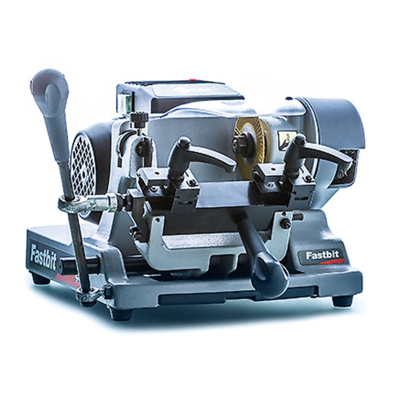
Page 8: Machine Description
FASTBIT Operating manual 1 MACHINE DESCRIPTION FASTBIT is a professional key-cutting machine for bit, double bit, pump keys, mail box keys and special keys. Fig. 3 The main parts of the machine are described below: • Main switch The key-cutting machine is connected to a power socket provided with a differential switch; when the machine is turned on by means of the switch (H) located on its right-hand side, the warning light (H1) comes on to show that the machine is live. - Page 9 • Cutting Tool The cutting tool (F) is the part of the FASTBIT used for cutting key blanks. The cutting tool is in HSS super rapid steel and is protected by a special cover (N) to ensure safe operation. •...
-
Page 10: Main Working Parts
E1 - tracer point spring locking knob N - cutting tool cover F - cutting tool P - brush/belt cover G - tracer point ring nut R - power supply socket H - main switch S - brush H1 - warning light (power) Copyright Silca 2014... -
Page 11: Technical Data
The main parts of the electric circuit on the key-cutting machine are listed below: 1) Power supply socket 2) Fuses 4 Amp rapid (230V) 3) Master switch 4) LED 5) Motor start switch 6) Motor with collector: 230V-50/60Hz 7) Condenser Fig. 7 Copyright Silca 2014... -
Page 12: Accessories Provided
FASTBIT Operating manual 1.4 Accessories provided FASTBIT comes with a set of accessories for its operation and maintenance (tools, hex wrenches, fuses) supplied in a special tool kit comprising: allen key 2,5 mm fuses 4 Amp rapid (230V) allen key 3 mm... -
Page 13: Transport
The packed machine can be carried by one person. 2.1 Packing The FASTBIT is packed in a strong cardboard box, the dimensions of which are shown in Fig. 8, suffi ciently robust to be used for storing the machine for long periods. -
Page 14: Machine Installation And Preparation
However, it is always advisable to check that the machine has not suffered any damage. 3.2 Environmental conditions To ensure that the best use is made of the FASTBIT key-cutting machine, certain parameters must be borne in mind: damp, badly ventilated sites should be avoided. -
Page 15: Separate Parts
FASTBIT Operating manual 3.5 Separate parts The separately packed parts must be installed on the FASTBIT key-cutting machine by the purchaser, as follows: 3.5.1 Carriage handle Screw the handle (B) onto the carriage lever (Fig. 11). Fig. 11 3.5.2 Power cable Connect the key-cutting machine power cable to the electricity mains (Fig. -
Page 16: Fixing Bracket
Fig. 13 3.6 Connection to the mains For the safety of the operator and the machine it is important to ensure that the machine is connected to the proper mains voltage by means of an earthed differential switch. Copyright Silca 2014... -
Page 17: Machine Regulation And Utilization
The FASTBIT key-cutting machine requires two types of calibration: axis and depth. Axis calibration: Axis calibration is used to adjust the cutting space on the key. The axis setting for the FASTBIT is fi xed and is established on assembly in our workshops. Fig. 15 Copyright Silca 2014... - Page 18 The ideal condition is achieved when the internal part of the left-hand stop is up against the right-hand side of the tracer point and the internal part of the right-hand stop is in contact with the right-hand side of the cutter. If this condition is not achieved, contact Silca After-Sales Service. Fig. 16...
- Page 19 Fig. 18 Turn the nut to the RIGHT (clockwise) to take the tracer point down. Result: LESS DEEP CUTS. Fig. 19 • Turn the nut to the LEFT (anticlockwise) to take the tracer point up. Result: DEEPER CUTS. Copyright Silca 2014...
-
Page 20: Cutting Operations
To activate the tilting movement: pull out the pin (D) and move handle (B) to round off the cuts. • To deactivate the tilting movement: fi t the pin (D) into its seat so that the carriage is locked in a fi xed horizontal position. Fig. 20 Fig. 21 Copyright Silca 2014... -
Page 21: Cutting Bit And Double Bit Keys
12) For double bit keys, turn both keys over and repeat the operations described above. 13) When cutting is fi nished, turn off the switch (K) and remove the keys. Fig. 22 Fig. 23 Fig. 24 Fig. 25 Copyright Silca 2014... - Page 22 FASTBIT Operating manual Fig. 26 Fig. 27 Copyright Silca 2014...
-
Page 23: Cutting Keys With Central Stop
6) Pull the carriage back and go on to another cutting point, then continue as for point 6. 7) When cutting is fi nished, turn off the switch (K) and remove the keys. Fig. 28 Fig. 29 Copyright Silca 2014... -
Page 24: Cutting Short Double Bit Keys
8) Use the knob to pull back the carriage and move into position for another cut, then continue as for point 6. 9) When cutting is fi nished turn off switch (K) and remove the keys. Fig. 30 Copyright Silca 2014... -
Page 25: Cutting Pump Keys
9) Complete all the bits in the same way and if necessary check the sides of the bits. 10) When the cutting operation is fi nished, take the carriage all the way back. 11) Turn off the switch (K) and remove the keys. Fig. 31 Fig. 32 Copyright Silca 2014... -
Page 26: Maintenance
4) Replace the brush and tighten the screw with the Allen key. 5) Remove the locking rod from the cutting tool shaft. 6) Place the cover (P) and secure with the 3 screws (P1). Fig. 33 Fig. 34 Copyright Silca 2014... -
Page 27: Replacing The Cutting Tool
3) Install the new cutting tool (pay attention to the rotation direction) and tighten the nut. 4) Remove the locking rod. 5) Re-place the protective shield (N). 6) Check calibration (see chap. 4.3) Fig. 35 Fig. 36 Copyright Silca 2014... -
Page 28: Replacing The Tracer Point
2) Replace the fuses (R1). 3) Close the fuses box and connect the power cable. ATTENTION: fuses must always be replaced with others of the same type and with the same Amps (4 Amp rapid). Fig. 38 Copyright Silca 2014... -
Page 29: Access To The Lower Compartment
2) Detach the 4 connectors (H2) and (H3) paying special attention to their position (Fig. 41). 3) Remove the switch making pressure on the tabs with a screwdriver (Fig. 42). 4) Fit the new main switch. 5) Reconnect the 4 connectors (H2) and (H3). Fig. 41 Fig. 42 Copyright Silca 2014... -
Page 30: Replacing The Motor
15) Connect the 2 connectors (H2) to the switch (H) and secure the earthing wire to its screw with a nut (T1). 16) Replace and secure the metal bottom (W) (chap. 6.5). 17) Replace the protective cover (P) and secure with the 3 screws (P1). Fig. 44 Fig. 45 Copyright Silca 2014... -
Page 31: Replacing And/Or Adjusting Tension On The Belt
6) Push the motor to the back until the belt has the right tension. 7) Tighten the four screws (M1) and the 4 nuts (M4). 8) Place the motor cover (P) and secure with the 3 screws (P1). Fig. 49 Copyright Silca 2014... -
Page 32: Replacing The Motor On Switch
2) Detach the connectors (Z) paying special attention to their position. 3) Remove the condenser (Y). 4) Fit the new condenser (Z). 5) Re-place the motor cover and secure with the 2 screws (M2). Fig. 52 Fig. 53 Copyright Silca 2014... -
Page 33: Disposing Of Machine
• For information about the collection system for such appliances please contact SILCA S.p.A. or another subject registered in the various National Rolls for other countries in the European Union. Household waste(or of similar origin) can be included in the separate collection system for urban waste. -
Page 34: Assistance
8.1 How to request service The guarantee attached to the key-cutting machines ensures free repairs or replacements of faulty parts within 24 months of purchase. All other service calls must be arranged by the customer with Silca or with a Silca service centre. - Page 35 | 14 | European Union DIRECTIVE 2006/95/CE (Low Voltage) and with the IEC/EN 60204 – 1 : 2009 Standards Claudio Tomasella of the Silca S.p.A. Research & Development Division is authorized to create a Technical File. General Manager Basic Production Center...
- Page 36 SILCA S.p.A. Via Podgora, 20 (Z.I.) 31029 VITTORIO VENETO (TV) Tel. 0438 9136 Fax 0438 913800 E-mail: silca@silca.it www.silca.biz Members of the Kaba Group...
Need help?
Do you have a question about the Fastbit and is the answer not in the manual?
Questions and answers