Table of Contents
Advertisement
Quick Links
Advertisement
Table of Contents

Related Manuals for Ametek 3050-RM


Summary of Contents for Ametek 3050-RM
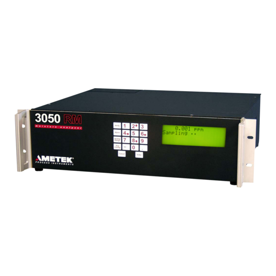
- Page 1 USER MANUAL 3050-RM Moisture Analyzer PN 305892901, Rev S...
- Page 2 AMETEK Process Instruments assumes no responsibility or liability for any errors or inaccuracies that may appear in this document. AMETEK Process Instruments is not responsible for any infringement of patents or other rights of third parties that may result from the use of this document. The content of this document is furnished for informational purposes only, is subject to change without notice, and does not represent a commitment or guaranty by AMETEK Process Instruments.
-
Page 3: Table Of Contents
Contents Safety Notes ..............................vii Electrical Safety ............................viii Grounding ..............................viii Sample Gas ............................... viii Personnel and Equipment Safety Information................ix Special Warnings and Information ......................xi Equipment Used in Class I, Division 2 Hazardous Locations ..........xi Dryer Warning .............................xi Electromagnetic Compatibility (EMC) ....................xii Warning Labels ............................ - Page 4 Function Keys ..........................2-17 Overview of Display ........................2-19 Initial Start-Up ............................2-20 Dry-Down Period ......................... 2-20 Configuring the 3050-RM Analyzer for Serial Communications ......... 2-21 Protocol ............................2-21 Special Addresses ........................2-23 Address $F0 ...........................2-23 Defined Commands (Master to Slave) .................. 2-23 Echo (A) ...........................2-24...
- Page 5 Production Codes .........................3-12 Moisture Unit ........................3-13 System Test ..........................3-14 Working From the AMETEK 3050 UHP Configurator Software..........3-15 UHP Configurator Software Installation ................3-15 Configuring the 3050-RM ......................3-16 Working From the General Tab ..................3-16 Saving Analyzer Configuration Settings ................3-18 Working From the Device Communication Tab ............3-19...
- Page 6 User Interface Board ........................4-22 Alarm Messages ........................... 4-23 SPECIFICATIONS ........................5-1 Compatible Gases ...........................5-1 3050-RM Moisture Analyzer Specifications ...................5-1 3050-RM Moisture Analyzer Approvals and Certifications ............5-2 APPENDIX A – QUICK REFERENCE CARD ................A-1 PN 305892901, Rev S vi | 3050-RM Moisture Analyzer...
-
Page 7: Safety Notes
Read this manual before beginning the installation and operation of the 3050-RM Analyzer. Failure to do so, and or use of the equipment in a manner not specified in this manual or accompanying documents, may impair the protection against fire, electrical shock and injury originally provided by this equipment. -
Page 8: Electrical Safety
Sample gas is toxic, flammable, or corrosive. Check the Sample gas line and all connections for leaks before powering up. Consult plant safety personnel for appropriate exhaust venting guidelines for specific Sample gas type. PN 305892901, Rev S viii | 3050-RM Moisture Analyzer... -
Page 9: Personnel And Equipment Safety Information
Personnel and Equipment Safety Information This section describes important safety information to avoid personal injury and dam- age to the equipment while installing, operating, maintaining, or servicing the equip- ment. All safety regulations, standards, and procedures at the analyzer location must be followed. - Page 10 Do Not Operate in Explosive Atmosphere To avoid injury or fire hazard, do not operate this product in an explosive atmosphere unless you have purchased options that are specifically designed for these environments. PN 305892901, Rev S x | 3050-RM Moisture Analyzer...
-
Page 11: Special Warnings And Information
AVERTISSEMENT – Risque d’explosion – La substitution de composants peut rendre ce materiel inacceptable pour les emplacements de Classe I, Division 2. Refer to the “Safety Critical Components” in the 3050-RM Analyzer Replacement Parts list in Chapter 4 of this manual. -
Page 12: Electromagnetic Compatibility (Emc)
The various configurations of the 3050-RM Moisture Analyzer should not produce, or fall victim to, electromagnetic disturbances as specified in the European Union’s EMC Directive. Strict compliance to the EMC Directive requires that certain installation techniques and wiring practices are used to pre- vent or minimize erratic behavior of the Analyzer or its electronic neighbors. -
Page 13: Warning Labels
Achtung – Heiße Oberfläche Environmental Information – WEEE This AMETEK product contains materials that can be reclaimed and recycled. In some cases the product may contain materials known to be hazardous to the environ- ment or human health. In order to prevent the release of harmful substances into the environment and to conserve our natural resources, AMETEK recommends that you arrange to recycle this product when it reaches its “end of life. - Page 14 This page intentionally left blank. PN 305892901, Rev S xiv | 3050-RM Moisture Analyzer...
-
Page 15: Overview
Freon 134A, Freon 152, helium, hydrogen, krypton, natural gas, neon, nitrogen, oxygen, propane, propene, SF6, and xenon. Carbon dioxide is also compat- ible, but requires an alternate Sensor assembly (refer to the 3050-RM Analyzer Replacement Parts list in Chapter 4 for ordering part number). Please contact the factory to confirm compatibility with other gases. -
Page 16: Controller/Communications
between the analyzer and your recording or data acquisition equipment. The 3050-RM Analyzer is configured, and analyzer parameters are set, by using either the analyzer display, keypad and function keys, or using an external PC. 4-line x 20-character LCD display that provides moisture data, system oper- ... -
Page 17: Contact Closure Signals
Contact Closure Signals The analyzer provides the following contact closure signals: System Alarm Activates (contact opens) when a condition exists that makes analyzer output questionable. Such conditions include: Cell temperature alarm Verify error Battery alarm Moisture Concentration Alarm Activates (contact opens) when a moisture concentration exceeds the pro- grammed alarm levels. -
Page 18: Moisture Sensor
Moisture Sensor Quartz Crystal Microbalance (QCM) The 3050-RM Analyzer uses a quartz crystal microbalance sensor to measure water vapor concentration. This is a piezoelectric device that is capable of extremely sensitive mass measurement. To make the QCM sensitive to water vapor the surface is coated with a thin film of hygroscopic material. -
Page 19: Gas Flow
Gas Flow Sample System The 3050-RM Moisture Analyzer sample system enables the analyzer to make reli- able water vapor measurements at concentrations down to 0.1 PPMV. The sample system serves several purposes: • It controls the sample conditions at the Sensor assembly (e.g., flow rate, temperature, pressure). -
Page 20: Sample Flow
Sample Flow Normal operation of the 3050-RM Analyzer uses an internal bypass, which increases the response speed of the system. However, the 3050-RM is capable of running in a gas-saver mode as well, which allows the analyzer to run on a sample volume of approximately 150 SCCM. -
Page 21: Solenoid Valves
The three-way solenoid valves (SV2, SV3, SV4) are used to select the gas stream that is passed through the sensor; the remaining two (2) streams are passed to the vent. During normal operation of the 3050-RM, the analyzer continuously cycles between the Sample- and Dry-Reference gas streams. This switching action modulates the water vapor concentration to which the sensor is exposed. -
Page 22: Verifying The Analyzer
During the verification operation, a new span factor is calcu- lated for the sensor, and this value is then applied for all subsequent readings. AMETEK recommends performing a verification cycle monthly. How- ever, no verification cycle should be performed during the startup of the analyzer. -
Page 23: Dew/Frost Point Measurements
Dew point values are calculated from the moisture concentration measure- ments (PPMV) and the sample or process pressure. For temperatures below 0 °C, the 3050-RM uses equations to determine the water vapor pressure over ice, rather than over super-cooled water. Thus, the 3050-RM reports a frost- point temperature consistent with the physical form of the condensed phase in a real process stream. - Page 24 This page intentionally left blank. 1-10 | 3050-RM Moisture Analyzer PN 305892901, Rev S...
-
Page 25: Installation And Start-Up
All regulatory agency and personnel safety proce- dures for your jurisdiction must be followed. Read this entire chapter before installing the 3050-RM Moisture Ana- lyzer. Failure to do so may impair protection against fire, electric shock and injury originally provided by this equipment. Do not use this analyzer in a manner not specified in this manual. -
Page 26: Pre-Installation Requirements
Analyzer Requirements Space Requirements The 3050-RM Analyzer requires an area 48 cm wide x 13 cm high x 42 cm deep (19" x 5.25" x 16.5") plus rear clearance for analyzer connections and proper ventilation (Figures 2-1.1, 2-1.2, and 2-1.3). It should be located as close as pos- sible to the sample tap. - Page 27 Figures 2-1.2. 3050-RM dimensions rear (bottom). Figures 2-1.3. 3050-RM dimensions top and sides. Installation and Start-Up PN 305892901, Rev S...
-
Page 28: Unpacking And Inspecting The Equipment
Unpacking and Inspecting the Equipment Remove any packing material from the 3050-RM Moisture Analyzer shipping crate. Check for damage. If equipment is damaged, notify the carrier and contact AMETEK (https://www.ametekpi.com/customersupport/aftermarket) immediately if parts are missing or damage is found, and to verify if damaged parts will require replacement prior to safely installing and operating the ana- lyzer/equipment. -
Page 29: Electrical Requirements
Electrical Requirements The 3050-RM Moisture Analyzer must be installed in a general purpose or Divi- sion 2 area. It does not have an On/Off power switch so power must be applied through a circuit breaker switch at the AC source. -
Page 30: Analyzer Installation
Sample Inlet temperature. Optimal results are obtained with the sample line maintained at 60 °C. Recommended Sample gas input tubing is 1/8-inch OD, electropol- ished 316L VAR stainless steel (AMETEK Part No. 257707000) or equiva- lent. Exhaust pressure must be 0–15 PSIG. -
Page 31: Rear Panel Connections And Interface Board
Fuse Receptacle 2 A, 250 V, time lag, T-type. Line Voltage Selector Select 120 Volt or 240 Volt line voltage. Figure 2-2. 3050-RM rear panel connections and inside of dryer compartment. Installation and Start-Up PN 305892901, Rev S... - Page 32 4–20 mA output to user recording equipment. Wiring supplied by user. 11 Alarm Contacts Connections for: Data Valid, Concentration Alarm, and System Alarm. Wiring supplied by user. Figure 2-3. 3050-RM Analog Interface board connections. 2-8 | 3050-RM Moisture Analyzer PN 305892901, Rev S...
-
Page 33: Installing The Dryer
Installing the Dryer Prior to operating the 3050-RM Analyzer, the Dryers must be installed. One (1) Dryer has been supplied with this analyzer. Make sure that you have the new Dryer and the new VCR gaskets available before beginning installation. - Page 34 For all subsequent replacement/installations of replacement dryer, you will need to enter a production code for the refer- ence dryer (see details in Chapter 2). 2-10 | 3050-RM Moisture Analyzer PN 305892901, Rev S...
-
Page 35: Gas Connections
3. Connect the exhaust tube to the analyzer Exhaust Outlet. The exhaust must be vented to an appropriate vent system. 4. Check all Sample Inlet and Exhaust Outlet fittings for leaks. Figure 2-5. 3050-RM rear panel gas connections. Installation and Start-Up 2-11... -
Page 36: Electrical Connections
If qualified service personnel are not avail- able, contact AMETEK Service. Voltage Selection The 3050-RM Analyzer comes from the factory set to operate on 120 VAC. If you must switch the setting to 240 VAC (or back to the 120 VAC setting), follow the procedure below. -
Page 37: Power Connection
Power Connection If the factory-supplied flexible power cord is not long enough or is not compli- ant with local standards, a 3-meter European-type harmonized power cord is also included. Ensure that the area is safe and replace the power cord as follows: 1. - Page 38 (Figure 2-8). Do not use the ground position on the power connector. Plug in the power connector. 8. Connect a proper, locally recognized plug or terminator to the end of your cord. 9. Replace the Rear Panel. 10. Reconnect power. 2-14 | 3050-RM Moisture Analyzer PN 305892901, Rev S...
-
Page 39: Communication Connections
Alarm & Alert Contacts Analog Output Figure 2-9. Communication connections on the 3050-RM Analyzer Interface board. 3. Connect the RS-232 or RS-485 serial communication to the analyzer. The RS-485 connection, analog output, and Conc Alarm/Data Valid contacts share the same cable. -
Page 40: Signal Connections (4-20 Ma)
Signal Connections (4–20 mA) 100 to 500 ohms Figure 2-10.1. Self-powered 4–20 mA output Meter connections. 100 to 500 ohms Supply 24 Volts Figure 2-10.2. Externally powered 4–20 mA Meter output connections. 2-16 | 3050-RM Moisture Analyzer PN 305892901, Rev S... -
Page 41: Overview Of The Keypad
Overview of the Keypad The 3050-RM Moisture Analyzer keypad (Figure 2-11) is used to access menus and sub-menus and system values for the function keys, and to configure your analyzer parameters. Verify Alarm FUNCTION Analog KEYS Range Test Config Cancel Enter Figure 2-11. - Page 42 To exit without saving when entering data. (Any changes made will not be saved.) To go back through previous levels, one level at a time, until the display returns to the normal operation screen, when browsing the menu list. 2-18 | 3050-RM Moisture Analyzer PN 305892901, Rev S...
-
Page 43: Overview Of Display
Overview of Display The default display has four (4) lines (Figure 2-13): Line 1 Sample concentration Line 2 Status message Line 3 Alarm message Line 4 Alarm value There is also a series of dots after the “Status” message that “beat” to indicate the analyzer is functioning. -
Page 44: Initial Start-Up
If the concentration value is still decreasing after the initial dry down period, allow additional dry down time. The 3050-RM Analyzer is now fully operational with factory default configura- tion of the analog output and concentration alarms. You are ready to do an initial Verify cycle. -
Page 45: Configuring The 3050-Rm Analyzer For Serial Communications
Configuring the 3050-RM Analyzer for Serial Communications Protocol The protocol used for the 3050-RM Analyzer is a master/slave, command/re- sponse communication with the master initiating all transfers. The message format for transfers initiated by the master is illustrated in Figure 2-15. - Page 46 Message format for slave Response Code acknowledge. The message format for slave failure response is illustrated in Figure 2-18. End Flag Command Code Figure 2-18. Error Code Slave failure response format. 2-22 | 3050-RM Moisture Analyzer PN 305892901, Rev S...
-
Page 47: Special Addresses
Special Addresses Addresses $F0 through $FF are reserved for special functions with address $F0 used as a broadcast address. Address $F0 Node address $F0 is used as a single point address (i.e., it is intended for use in configurations with a single slave). The slave will respond to all messages with node address $F0. -
Page 48: Echo (A)
2-21.1 and 2-21.2 (Variable tables) for a list of defined handles for system variables. Example: Master: >34F0512[CR] Slave: A1234540[CR] Start Verify (G) Initiates a verify cycle. Example: Master: >34G??[CR] (Note the use of wildcard in place of checksum) Slave: A[CR] 2-24 | 3050-RM Moisture Analyzer PN 305892901, Rev S... -
Page 49: Write Data (H)
Write Data (H) The data field of this frame contains the handle for a system variable. See Fig- ures 2-21.1 and 2-21.2 (Variable tables) for a list of defined handles for system variables. Example: Master: >34H05123.40C[CR] Slave: A[CR] Write Cell EEPROM (L) Copy cell serial number and cell calibration coefficients into cell EEPROM. -
Page 50: Defined Responses (Slave To Master)
ASCII failure code. Defined failure codes are given in the table below. Example: Slave: N01[CR] Failure Code Description Unknown Command Byte Check Sum Figure 2-20. Parameter Out of Range Defined Failure Codes. 2-26 | 3050-RM Moisture Analyzer PN 305892901, Rev S... -
Page 51: Variables Table
Baud Serial communication speed Integer 9600 SerialMode RS-485 two-wire or four-wire mode Integer 1(four-wire) NodeAddress RS-485 analyzer address String AnalyzerName AMETEK analyzer name String 3050-RM Sample gas name String Nitrogen Alarm1Hi High concentration limit Float 100.0 Alarm1Lo Low concentration limit... - Page 52 Moisture units of measure set Integer PpmW PpmV to ppmW conversion factor Float 0.6431 IgnoreSpanDrift Ignore span drift flag Integer OldMoistSpan Moisture span before the correction Float Figure 2-21.2. Variables table (continued). 2-28 | 3050-RM Moisture Analyzer PN 305892901, Rev S...
-
Page 53: Controller/Interface
Controller/Interface Communicating with the 3050-RM Moisture Analyzer can be done using the built-in user interface or using the AMETEK 3050 Analyzer Configurator Soft- ware. Both methods are described in this chapter. Working From the Built-in User Interface The built-in user interface consists of the LCD display screen and keypad on the front of the 3050-AM Moisture Analyzer. - Page 54 Figure 3-2. Menu Map for 3050-RM Moisture Analyzer. 3-2 | 3050-RM Moisture Analyzer PN 305892901, Rev S...
-
Page 55: Verify Key
Verify Key Use the Verify key to define on-demand verify settings. VERIFY Hold Outputs Enable Disable Adjust Span Enable Disable Verify Figure 3-3. Abort Main Menu, Verify key. Hold Outputs Enable Select this function to hold the output at the last valid reading during a verify. -
Page 56: Alarm Key
Enter the high limit value in moisture units selected. Low Limit Enter the low limit value in moisture units selected. Enable Alarm Select Enable or Disable to activate the moisture concentration alarm relay. 3-4 | 3050-RM Moisture Analyzer PN 305892901, Rev S... -
Page 57: Range Key
Range Key Use the Range key to define your 4–20 mA output setting. Use this setting to scale the 4–20 mA output. The 4–20 mA output is propor- tional to the moisture readings. RANGE Enter Maximum Conc Value Enter Figure 3-5. Minimum Conc Value Main Menu, Range key. -
Page 58: Config Key
Enter a value from '1' to '9' . The default is '5' . Back Light Select On or Off. The default is On. Font This is a factory-set parameter that identifies the type used for the display on the analyzer. 3-6 | 3050-RM Moisture Analyzer PN 305892901, Rev S... -
Page 59: Communication
Communication Select communication setup. Config Communication Node Enter Address Address 9600 Baud Rate 19200 RS-485 Two Wire Mode Figure 3-6.3. Four Wire optional Communication sub-menu. Node Address Enter the address for RS-485 serial communications (0–240). Address 240 is reserved (see the “Special Addresses” section in Chapter 2 for details). -
Page 60: Sample Gas
Gas K Factor. The Gas K Factor is a parameter used by the Flow Meter in the 3050-RM to adjust for the molar heat capacities of different gases. Nitrogen is used as the Reference gas for the K factors, and its value is defined as 1.000. - Page 61 Gas Saver In the default configuration the 3050-RM Analyzer runs with the internal bypass valve open, so that the total flow through the analyzer is greater than 1 SLPM. This high sample flow rate helps to improve the response speed of the system.
-
Page 62: Clock
Select the day of the week from the list. Month Enter the 2-digit value for the month. Hour Enter the value using the 24-hour clock. Minute Enter the 2-digit value for minutes. 3-10 | 3050-RM Moisture Analyzer PN 305892901, Rev S... -
Page 63: Verify Schedule
('0') is the starting hour. Duration Enter the Verify period value in minutes. AMETEK recommends performing a verification every 24 hours for the first month of operation. After this start-up period, the analyzer will have dried down sufficiently to increase the verification interval to 1 month. -
Page 64: Production Codes
Use caution, as entering a “new” value informs the analyzer that a new dryer has been installed in the reference leg of the analyzer. The remaining dryer capacity is reset when a new number is entered. 3-12 | 3050-RM Moisture Analyzer PN 305892901, Rev S... -
Page 65: Moisture Unit
Moisture Unit Config PPmV PPMV Centigrade Centigrade Pressure (KPa)* Fahrenheit Moisture Unit Select Unit Fahrenheit Pressure (KPa)* lbs/mnscf mg/Nm³ ppmW Figure 3-6.8. Moisture Unit sub-menu. Select Unit The units for the moisture readings can be selected from a list. Pressing Enter at the Select Unit prompt displays the list. -
Page 66: System Test
Tests the analog output by allowing the user to set outputs to 4, 12, or 20 mA. Test Serial Communications Performs a “loop back” test and reports the result to the display. 3-14 | 3050-RM Moisture Analyzer PN 305892901, Rev S... -
Page 67: Working From The Ametek 3050 Uhp Configurator Software
3. Follow the instructions on the subsequent screens to complete the instal- lation. When you get to the Setup Complete screen, click Finish to com- plete the installation. The default location for the 3050-RM UHP software is in the AMETEK, Inc. folder. -
Page 68: Configuring The 3050-Rm
After initial setup, any changes to the analyzer communications parameters must be made using the Device Communications tab. These changes must be made before you make any changes to the computer serial port settings. 3-16 | 3050-RM Moisture Analyzer PN 305892901, Rev S... - Page 69 PC Communications Setup Options Displays information that has been configured from the Serial Port Con- figuration dialog box. Click the Setup button to configure PC Communications. The Serial Port Communication dialog box opens (Figure 3-8). Figure 3-8. PC Serial Communications setup dialog box.
-
Page 70: Saving Analyzer Configuration Settings
To save all of the settings made on the General tab, click Apply. To save settings and exit the program, click Apply+Exit. To abort changes you have made, click Cancel+Exit. This will close the Con- figurator Software program. 3-18 | 3050-RM Moisture Analyzer PN 305892901, Rev S... -
Page 71: Working From The Device Communication Tab
Working From the Device Communication Tab For initial setup of PC communication parameters, use the Setup but- ton on the General tab. Figure 3-9. Device Communication setup tab. Configuring Multiple Analyzers Use the Device Communication tab to set the analyzer’s communication parameters to agree with the PC settings when controlling analyzers in a daisy chain. -
Page 72: Saving Your Settings
To save settings on the Device Communications tab, click Apply. To save settings and exit the program, click Apply+Exit. To abort changes you have made, click Cancel+Exit. This will close the Con- figurator Software program. 3-20 | 3050-RM Moisture Analyzer PN 305892901, Rev S... -
Page 73: Working From The Setup Tab
Working From the Setup Tab Use the Setup tab to define analyzer parameters. Figure 3-10. Setup tab. Select the gas being sampled. Dewpoint Temp – If you select dewpoint temp, the Process Pressure box is activated and you must enter a process pressure parameter in kPa. - Page 74 Check this box to enable the concentration alarm. High Limit Enter the high limit for the concentration alarm. Low Limit Enter the low limit for the concentration alarm. To Save settings on the Setup tab, click Apply. 3-22 | 3050-RM Moisture Analyzer PN 305892901, Rev S...
-
Page 75: Working From The Schedule Tab
Working From the Schedule Tab Use the Schedule tab to schedule routine Verification. Figure 3-11.1. Schedule tab. Abort button Click to terminate Verification. Verify Now button Click to begin Verify cycle now. Adjust Offset check box Checked The analyzer performs an offset adjustment at the end of the Verify cycle. - Page 76 Scheduled Verification Schedule routine Verifications by clicking the Daily, Weekly, or Monthly button. Never No verify will be done. Scheduling slots at the bottom of the box are not available. 3-24 | 3050-RM Moisture Analyzer PN 305892901, Rev S...
-
Page 77: Saving Your Settings
Daily Select the time of day by entering a number in the Hour slot at the bottom of the box. The analyzer uses a 24-hour clock. Example: 1:00 PM = 13 hours. Weekly Select the day of the week from the drop-down list under Day of the week at the bottom of the box. -
Page 78: Working From The Status Tab
The file format is Excel-compatible CSV format. Concentration readings data for the last 24 hours can be written to this file from the analyzer’s data buffer. 3-26 | 3050-RM Moisture Analyzer PN 305892901, Rev S... -
Page 79: Working From The Monitor Tab
Working From the Monitor Tab Use the Monitor tab to check on analyzer operation. From this tab you can also collect data from the analyzer. Figure 3-13. Monitor tab. Controller/Interface 3-27 PN 305892901, Rev S... -
Page 80: Data Capture
The preferred data collection rate is “0.5” minutes and is set as the default. A record is created every 30 seconds. The collection rate can be increased to one (1) minute or more. 3-28 | 3050-RM Moisture Analyzer PN 305892901, Rev S... -
Page 81: Maintenance And Troubleshooting
The operations in this chapter should be performed only by qualified service personnel experienced in electrical safety techniques. Before working on the 3050-RM Analyzer, read the entire procedure you will be performing to learn how to safely and properly perform maintenance or service the analyzer. -
Page 82: Aftermarket Excellence And Long-Term Commitment To Safety And Quality
Scan the QR code or click the link below to request expert Aftermarket support for parts, repairs, service, training, and more: www.ametekpi.com/customersupport/aftermarket 4-2 | 3050-RM Moisture Analyzer PN 305892901, Rev S... -
Page 83: 3050-Rm Analyzer Replacement Parts
3050-RM Analyzer Replacement Parts * Indicates recommended stock spare parts to have on hand. Refer to the Figure numbers listed for the location of the part. Part Description AMETEK Part No. Figure Battery, Lithium 280750043 4-11 Fuse*, 2 Amp, 250 V... -
Page 84: Servicing The 3050-Rm Analyzer
Servicing the 3050-RM Analyzer Make sure that power has been disconnected from the analyzer before attempting to remove or replace any of the parts. Figure 4-1. 3050-RM exploded view. 4-4 | 3050-RM Moisture Analyzer PN 305892901, Rev S... - Page 85 Figure 4-2. 3050-RM sample system. Figure 4-3. Sensor removal in 3050-RM. PN 305892901, Rev S Maintenance and Troublshooting | 4-5...
-
Page 86: Sensor
1. Remove the Analyzer Cover from the analyzer. 2. Remove the Sample Oven Cover (Figure 4-9). Facing the front of the 3050-RM Analyzer, the Sensor is the small PC board with two (2) metal cans in the center of the sample manifold plate (Figure 4-2). -
Page 87: Mass Flow Meter
Removing the Mass Flow Meter: 1. Remove the Analyzer Cover from the analyzer. 2. Remove the Sample Oven Cover. Facing the front of the 3050-RM Analyzer, the Mass Flow Meter is the small black box on the left-hand side of the Sample Oven (Figure 4-3). - Page 88 6. Replace the Sample Oven Cover, and secure it with the two (2) nuts. 7. Replace the Analyzer Cover, and secure it with the mounting nuts. Figure 4-4. 3050-RM Mass Flow Meter. 4-8 | 3050-RM Moisture Analyzer PN 305892901, Rev S...
-
Page 89: Moisture Generator
Removing the Moisture Generator 1. Remove the Analyzer Cover from the analyzer. 2. Remove the Sample Oven Cover. Facing the front of the 3050-RM Analyzer, the Moisture Generator is located left-center on the sample manifold plate, above the pressure transducer, between the Flow Meter and the Sensor assembly. - Page 90 Figure 4-5. 3050-RM Moisture Generator. 4-10 | 3050-RM Moisture Analyzer PN 305892901, Rev S...
- Page 91 8. Remove the old generator from the bracket, and set it aside. Use caution when disconnecting the Moisture Generator and pressure transducer from the sample system. The tubes are delicate and care should be taken not to transfer torque to them. Figure 4-6.
-
Page 92: Installing The New Moisture Generator
If you are removing the 3-way solenoid that is directly behind the fan, you will need to remove the fan first (Figure 4-7.1) so that you can ac- cess the screws that hold the solenoid in place. 4-12 | 3050-RM Moisture Analyzer PN 305892901, Rev S... - Page 93 6. Using a flat-head screwdriver, remove the screws that hold the valve body to the manifold; set the screws aside. Lift-off the solenoid valve and reserve the O-rings for the replacement solenoid. Figure 4-7.1. 3050-RM Solenoids. PN 305892901, Rev S Maintenance and Troublshooting | 4-13...
-
Page 94: Installing The New Solenoid
5. Replace the Sample Oven Cover and secure it with the two (2) nuts (Figure 4-1). 6. Replace the Analyzer Cover and secure it with the mounting screws. Figure 4-7.2. 3050-RM Solenoid replacement. 4-14 | 3050-RM Moisture Analyzer PN 305892901, Rev S... -
Page 95: Dryers/Contaminant Traps
5. Loosen the 1/8-inch fittings on the dryer(s)/trap and remove the dryer(s)/ trap from the analyzer. Discard the used gaskets from the fittings. Figure 4-8. 3050-RM Dryers. PN 305892901, Rev S Maintenance and Troublshooting | 4-15... -
Page 96: Installing The New Dryer/Trap
Installing the New Dryer/Trap Minimize the time that the dryer is exposed to the atmosphere after removing the protective caps. AMETEK recommends that the dryer be exposed for less than a minute. 1. Insert the replacement dryer into the dryer port on the analyzer. Use the new gaskets provided with the dryer in each of the fittings. -
Page 97: Maintenance Of The Electronics Module
• Once you remove the Electronics Module from the 3050-RM Enclosure, you can place it on the 3050-RM Enclosure as a resting fixture. However, take care not to scratch the 3050-RM Enclosure with the Electronics Module (a piece of cardboard can be placed under the Electronics Module to protect the enclosure). - Page 98 Figure 4-9. Electronics Module 4-18 | 3050-RM Moisture Analyzer PN 305892901, Rev S...
-
Page 99: Analog Interface Board
Analog Interface Board The Analog Interface board (AMETEK Part No. 591144901) is located on top of the MCU board at the front of the Electronics Module (Figures 4-9 and 4-10). Removing the Analog Interface Board • Remove the four (4) knurled screws that secure the board in place. One (1) of the screws secures the PSV board in place. -
Page 100: Mcu Board
MCU Board The MCU board (AMETEK Part No. 305110907S) is located below the Analog Interface board (Figures 4-9 and 4-11). Removing the MCU Board • Remove the Analog Interface board as described in the previous section. • Using a 1/16-inch hex wrench, remove the four (4) standoffs that secure the MCU board in place. -
Page 101: Reinstalling The Electronics Module
Reinstalling the Electronics Module Once you have serviced the various components in the Electronics Module, reassemble the analyzer. 1. Carefully reposition the Electronics Module above and to the front of the analyzer. Lower the module into the analyzer so the screws at the four (4) corners can be attached. -
Page 102: Board Connections
Board Connections User Interface Board Heater Wire 120 Volt System RS-485 Alarm 120-Volt System Alarm RS-485 Heater Wire Circuit Side 120-Volt RS-485 System Alarm Figure 4-12. User Interface board connections. 4-22 | 3050-RM Moisture Analyzer PN 305892901, Rev S... -
Page 103: Alarm Messages
Contact AMETEK Service if problem persists. Flow Alarm Gas flow out of range (45–55 SCCM). Corrective Action: Check inlet and outlet pressures. Contact AMETEK Service if problem persists. Battery Alarm Low battery voltage detected. Corrective Action: Replace battery or contact AMETEK Service. - Page 104 Alarm Reference Gas Alarm Delta frequency is less than -0.3 Hz. Corrective Action: Verify analyzer. Check and/or replace dryer. Contact AMETEK Service if problem persists. Enclosure Temperature Electronics compartment temperature Exceeds 70 °C. Corrective Action: Contact AMETEK Service. Moisture Generator Date Alarm Moisture generator is more than two (2) years old.
- Page 105 The pressure limit is different for each of the gases in the list. Corrective Action: Contact AMETEK Service. The Data Valid contact Opens on all alarms and stays Closed during normal functions and readings. An Open Data Valid contact indicates Verification is in process or an alarm condition.
- Page 106 This page intentionally left blank. 4-26 | 3050-RM Moisture Analyzer PN 305892901, Rev S...
-
Page 107: Specifications
SF6, and xenon. Carbon dioxide requires a custom Sensor assembly. Contact the factory to confirm compatibility with other gases. Read the Dryer Warning in the “Special Warnings and Information” section in the beginning of this manual for more information. 3050-RM Moisture Analyzer Specifications Specification Description Range Calibrated range of 0–2500 PPMV. -
Page 108: 3050-Rm Moisture Analyzer Approvals And Certifications
48 cm (19 inches) Height: 13 cm (5.25 inches) Depth: 42 cm (16.5 inches) Net Weight 10.9 kg (24 lb) 3050-RM Moisture Analyzer Approvals and Certifications Design Classifications MET Certified to: UL/CSA General Safety Requirements: UL61010, CAN/ CSA C22.2 No. 1010.1... -
Page 109: Appendix A - Quick Reference Card
Verify Cycle: AMETEK does not recommend performing a Verify cycle during initial startup. The ana- lyzer and its internal generator should be allowed to equilibrate for at least 24 hours before you run a Verify cycle. - Page 110 A-2 | 3050-RM Moisture Analyzer PN 305892901, Rev S...
- Page 111 AMETEK Process Instruments delivers worldwide sales and service support through a network of direct and factory-trained global distribution channels. AMETEK Service Assistance Program plans offer coverage up to 24 hours a day, 365 days of the year. As worldwide experts in the manufacture of process analyzers and instrumentation, we have supplied solutions to industry since 1962, providing the widest range of analysis technology available.
Need help?
Do you have a question about the 3050-RM and is the answer not in the manual?
Questions and answers