
Related Manuals for Ametek 303B


Summary of Contents for Ametek 303B
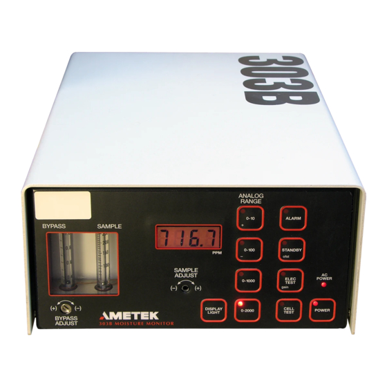
- Page 1 Model 303B Moisture Monitor User Manual Process Instruments 455 Corporate Boulevard Newark, DE 19702 PN 303230001 , Rev. U...
-
Page 2: Offices
© 2009 AMETEK This manual is a guide for the use of the 303B Moisture Monitor Analyzer. Data herein has been verified and validated and is believed adequate for the intended use of this instrument. If the instrument or procedures are used for purposes over and above the capabilities specified herein, confirmation of their validity and suitability should be obtained;... -
Page 3: Table Of Contents
Table of Contents Offices ........................ii Safety Notes ......................vii Warning Labels ....................viii SPECIAL WARNINGS AND INFORMATION FOR EQUIPMENT USED ..IN HAZARDOUS LOCATIONS ................ ix WARRANTY AND CLAIMS ................x Chapter 1 Overview Purpose ........................1-1 Description ......................1-1 Sample System Requirements ................1-2 Sample Adjust ....................1-2 Tubing ......................1-3 Flow Diagram ....................1-4... - Page 4 Flashing LED Positions ................5-7 Parameter Settings ..................5-8 Gain ........................5-8 Factory A/D Gain ..................5-9 Trouble-Shooting Chart ................5-10 Power Supply Board .................5-12 Chpater 6 Service and Parts Parts Ordering Information ...............6-1 Parts Lists ......................6-2 Accessories ....................6-3 303B Moisture Analyzer Manual iv |...
- Page 5 Apprndix A Conversion Chart Dew Point ......................A-1 Notes ........................A-1 Appendix B Nomogram Conversion to Relative Humidity ..............B-1 Appendix C Nomogram Dew Point with Pressure .................. B-1 Appendix D Glossary of System Conditions Appendix E Flow Meter Settings Contents | v...
- Page 6 303B Moisture Monitor 303B Moisture Analyzer Manual vi |...
-
Page 7: Safety Notes
Health Hazards Precaution Data: if and when hazardous chemicals or adverse health factors affect the environment or use of the equipment, appropriate precautions are provided. Service operations given or implied in this manual should be performed only by AMETEK or other qualified personnel. -
Page 8: Warning Labels
Achtung - Heiße Oberfläche Environmental Information (WEEE) This AMETEK product contains materials that can be reclaimed and recycled. In some cases the product may contain materials known to be hazardous to the environment or human health. In order to prevent the release of harmful substances into the environment and to conserve our natural resources, AMETEK recommends that you arrange to recycle this product when it reaches its “end of life.”... -
Page 9: Special Warnings And Information For Equipment Used
SPECIAL WARNINGS AND INFORMATION FOR EQUIPMENT USED IN HAZARDOUS LOCATIONS This Equipment is Suitable for Use in Class I, Division 2, Groups ABCD or Non-Hazardous Areas Only. Warning - Explosion Hazard - Substitution of Components May Impair Suitability for Class I, Division 2. WARNING AVERTISSEMENT - RISQUE D’EXPLOSION - LA SUBSTITUTION DE COMPOSANTS PEUT RENDRE CE MATERIEL INACCEPTABLE POUR LES EMPLACEMENTS DE... -
Page 10: Warranty And Claims
Resale items warranty is limited to the transferable portion of the original equipment manufacturer’s warranty to AMETEK. If you are returning equipment from outside the United State, a statement should appear on the documentation accompanying the equipment being returned declaring that the goods being returned for repair are American goods, the name of the firm who purchased the goods, and the shipment date. -
Page 11: Chapter 1 Overview
303B Moisture Monitor. Gas correction factor tables are given in Appendi- ces A through C. A glossary of terms is given in Appendix D. Purpose The Model 303B measures the water vapor content of most gases, or a mixture of gases, in ppmv or lb/MMscf in Division 2 areas. Description... -
Page 12: Sample Adjust
Filter out all particulate matter larger than 10 µm; if not, the internal filter will foul quickly. • Be sure sample temperature does not exceed 40°C. • Be sure the sample is free of oil mist. 1-2 | 303B Moisture Analyzer Manual... - Page 13 Sample gas tubing (PN A.571061017) is recommended. It should be chemi- cally cleaned and passivated, thermocouple grade 316 stainless steel. Cop- per, brass, and polycarbonate are not to be used. Most plastics or elasto- mer materials are unsatisfactory because of their relatively high moisture permeability.
- Page 14 50 VDC Figure 1-2. 303B Flow Diagram 1-4 | 303B Moisture Analyzer Manual...
-
Page 15: Optimising Response Time
Optimizing Response Time The built-in bypass system is always used to optimize response time. Un- less the sample gas is hazardous or costly, bypass flow should be as high as possible. The bypass system also is valuable with the instrument in portable service analyzing discrete samples. -
Page 16: Parameters Affecting Operation
Parameters Affecting Operation Flow Calibration The 303B is an easy to operate, but flow dependent instrument. To ob- tain an accurate moisture measurement the operator must set the sample flow to the equivalent of 100 mL/min at 1 atmospheric pressure and 25°C (77°F). -
Page 17: Pressure
pressure. Volumetric flow measuring devices such as the bubble-o-meter are not affected by different gas densities and will provide the correct flow independent of density (at constant temperature and pressure). Pressure Since the flow controller maintains a constant flow, sample input pressure changes do not affect instrument response. -
Page 18: Cell
OFF with low ppm readings, such that battery power can be conserved. The relay works against a single setpoint setting. In the fail-safe mode, the relay coil is ON when the moisture reading is below the alarm setpoint 1-8 | 303B Moisture Analyzer Manual... -
Page 19: Special Functions
and OFF when the reading goes above the setpoint. Since the coil is nor- mally ON with low readings, if power is lost accidentally, the coil turns OFF which, in turn, reverses the relay contacts as if a high ppm reading oc-curred;... -
Page 20: Stand By Test
(ICs), and should always be between 4.80 and 5.20 volts. If this voltage is out-of-range, most likely the 303B will not operate at all and the function cannot be accessed. If this function shows an out-of- range condition, voltage must be measured directly at the power supply board to verify the voltage error, and the power supply board should be replaced. - Page 21 rect factory_gain number for a particular display/cpu board. Through this, each instrument meets the published specifications. Since this calibration is so complex, it is not recommended that this number ever be changed. In case the number is accidentally overwritten or changed, a label at-tached to the display/cpu board has the factory_gain number inscribed.
-
Page 22: Zeroing Example
100; the 50 to 100 ppm readings then will be 0 to 100 percent of the 4 to 20- mA output. As stated earlier, 0 to 100 ppm will be displayed even though the real moisture levels are 50 to 100 ppm. 1-12 | 303B Moisture Analyzer Manual... - Page 23 The mathematics to map a specific range into another range are listed below. This technique assumes that gain and offset are at their default values, 1.0 and 0.0. Actual ppm Values = Act_low and Act_high Mapped Into Values = Map_low and Map_high (Map_high –...
- Page 24 This page intentionally left blank. 1-14 | 303B Moisture Analyzer Manual...
-
Page 25: Chapter 2 Specifications
SPECIFICATIONS Operating Environmental Range 0° to 52°C 10-90% RH Non-Condensing Pollution Degree 2 Installation Category II 0-2000 Meters Altitude Sample gas Temperature Range 10° to 52°C Temperature Stability 0.5 % per °C Maximum Inlet Pressure 690 kPa (100 psi) gauge Minimum Inlet/Outlet Pressure Differential 69 kPa (10 psi) gauge... - Page 26 6.4 kg (14 lb) Factory Defaults Factory Gain: Specified on board label Gain: 1.00 Offset: Alarm Setpoint: 2000 ppm or 100 lb/mmscf Analog Output Range: 0 to 2000 ppm or 0 to 100 lb/mmscf 2-2 | 303B Moisture Analyzer Manual...
- Page 27 Approvals and Certifications UL/CSA General Safety Requirements Class 1, Division 2, Groups ABCD T4A Electromagnetic Compatibility Directive; EN61326-1 Industrial Low Voltage Directive; EN61010-1 Pressure Equipment Directive Complies with all relevant European direc tives Specifications...
- Page 28 This page intentionally left blank. 2-4 | 303B Moisture Analyzer Manual...
-
Page 29: Chapter 3 Installation
Analyzer Site Preparation General This section provides instructions to connect and apply power to the 303B and to connect it to a sample source. Refer to Appendices B and C for additional sampling considerations and parameters affecting operation. -
Page 30: Power
AMETEK Service. The 303B is shipped with three feet (.91m) of nondetachable, extra-hard usage (Class 1, Div 2 requirement), AC power cord, pre-terminated at the unit. For European and other overseas products, this cable will be of the CENELEC Harmonized type. - Page 31 See NEC section 501- 3b6 or CEC 18-172,174 When the 303B is connected to the AC power mains, the internal battery will either be in a state of recharge, or full charge, maintained by the internal battery charger portion of the power supply.
-
Page 32: External Dc Operation
WARNING originally provided by this equipment. When the 303B is properly connected to a vehicle, the internal battery will be in a state of recharge or full charge, maintained by the internal bat-tery charger portion of the power supply. Note that the front panel AC LED does not illuminate during external DC operation. -
Page 33: Start Up
3. Check that jumper plug JP2 is set as desired for your alarm operation; pins 1 and 2 (F) for fail-safe (relay actuated with readings below setpoint, or pins 2 and 3 (L) for low power (relay actuated with readings above set-point). 4. - Page 34 Close the BYPASS ADJUST valve. Do not over tighten. Connect a precision flow meter such as the bubble-o-meter (figure 3-4) to the GAS OUT fitting. The 303B flow meters must be calibrated for all sample gases (refer to Appendix E for correction factors).
-
Page 35: Pressure Vacuum Pump
69 kPa (10 psi) gauge, you must increase the pressure with either a pressure (option 271803001 A in figure 3-2) or a vacuum pump (option B). An AMETEK pump (PN ) or (271813001, 240V) can be used in either configuration. Keep in mind that some pressure pumps will add moisture to the sample. -
Page 36: Interconnection Diagram
Figure 3-2 Interconnection Diagram (illustration) 3-8 | 303B Moisture Analyzer Manual... -
Page 37: Grounding Methods
Figure 3-3 Proper and Improper Grounding Methods Installation... -
Page 38: System Installation Bubble-O Meter
WARNING When making measurements at low flow rates with gases like helium or hydrogen, form several films ahead of the one being timed to prevent gas loss by diffusion through the film. 3-10 | 303B Moisture Analyzer Manual... - Page 39 Figure 3-4 Bubble-O-Meter PN 303030006. Installation 3-11...
- Page 40 This page intentionally left blank. 3-12 | 303B Moisture Analyzer Manual...
-
Page 41: Chapter 4 User Interface
USER INTERFACE OPERATION Controls and Indictors Control Function Normal Measuring BYPASS flow meter Sets and reads bypass gas flow rate. Mid-scale. SAMPLE flow meter Reads sample flow rate. 100 cc/min at 1 atm Moisture display Liquid crystal display (LCD) shows moisture Moisture reading value or other data depending on mode. -
Page 42: Transportation
If the instrument is used to measure moisture in toxic or flammable gases, the GAS OUT must exhaust to an area deemed safe and appropriate by the local authority having ju- WARNING risdiction. Take appropriate precautions. 4-2 | 303B Moisture Analyzer Manual... - Page 43 The effect of electrolyzed reformed water can be easily determined. The reformation of water is constant and independent of flow within the instrument range. Generally, the error resulting from air or oxygen streams can be as high as 10 percent. Use the following technique to reduce this effect: 1.
- Page 44 This page intentionally left blank. 4-4 | 303B Moisture Analyzer Manual...
-
Page 45: Chapter 5 Maintenance
WARNING TERY IN THIS SITUATION! Service operations given or implied in this section should be performed only by AMETEK or other qualified personnel. There are no operator- replaceable parts internal to the unit. General Frequency of analyzer maintenance depends almost entirely on the condi- tion of the sample stream being monitored. -
Page 46: Moisture Monitor Interior View
Figure 5-1. Moisture Monitor Interior View 5-2 | 303B Moisture Analyzer Manual... -
Page 47: Parts Replacement
Parts Replacement Flow Meter Tubes (Figure 5-1) Turn off power using front panel switch and disconnect the unit from the power source. Shut off sample flow at the source and purge the line. Shut off purge. Remove the screws and lift off the cover. Disconnect the “U”... -
Page 48: Main Ac Fuse
Remove the two bracket nuts, move the bracket to the side, and lift out the battery. If new battery does not fix problem, check polarity. Allow 24 hours for initial charge. On battery replacement, use only AMETEK 303020001, nominal 12Vdc @ 5 Amp hour. WARNING CPU/Display Board To gain access, perform steps 1, 2 and 3 above under Flow Meter Tubes section. -
Page 49: Testing
Testing Leak Test The following test will assure that the monitor is free from leaks that will interfere with proper operation. Cap off the GAS OUT fitting. Attach a 0 to 1000-kPa (150-psi) leak-free pressure gauge and leak-free shutoff valve to the GAS IN fitting (the gauge must be between the valve and the monitor). -
Page 50: Power Supply Voltage Test
A coding scheme — checksum — is stored with the data to make sure the data does not change during storage. On power-up, the stored parameters are read and checked against the checksum. If there is a problem with checksum reading, read error Er01 5-6 | 303B Moisture Analyzer Manual... -
Page 51: Display And Led Test
is displayed. If there is a problem storing values during parameter value en-tering, write error Er02 is displayed. Only the Analog Range param- eter entry does not give a display feedback when it is stored correctly. For either error, power-down and reenter the parameters as directed in the procedures on pages 5-7 and 5-8. -
Page 52: Parameter Settings
Press the + or – key to increment or decrement the display to the de- sired valve. When the desired value is displayed, press GAIN to store the value; ProG will be displayed until the value is stored, followed by the nor- mal LED/display test. 5-8 | 303B Moisture Analyzer Manual... -
Page 53: Factory A/D Gain
NOTE If the ALARM, CELL TEST, 0-1000 (50), 0-2000 (100), or DISPLAY LIGHT key is pressed during the routine, the new value is not stored and normal moisture measuring begins. Factory A/D Gain Factory A/D gain linearizes the cpu/display board to the moisture cell. Press the POWER key (LED OFF). - Page 54 Check and adjust flow rate on gas with a known moisture content Leak in sample system Do a leak test Dirty flow meter Replace flow regulator Shorted or partially Remove, flush and recoat cell 5-10 | 303B Moisture Analyzer Manual...
- Page 55 STANDBY (display blank) In standby - battery power shorted cell LEDs flashing save mode Symptom Possible Cause Corrective Action Replace filter or flow Clogged filter or flow meter Flow slow or erratic regulator Replace fuse Blown fuse F1 AC POWER LED does not light with unit connected to ac supply After power up, display...
- Page 56 CELL TEST and any one Press CELL TEST to exit. ANALOG RANGE LEDs flashing Low Battery Analyzer will not turn off Recharge the battery by in battery mode running the analyzer in the AC power mode. 5-12 | 303B Moisture Analyzer Manual...
-
Page 57: Service And Parts
SERVICE AND PARTS Parts Ordering Information This section lists parts AMETEK considers practical to stock and supply for replacement. The parts are listed in Table 6-1 and identified by reference designation or item numbers in Figures 6-1, 6-2, and 5-1. - Page 58 Back Panel Overlay (120 V) 303212901 Back Panel Overlay (240V) 303212902 Battery 12 V , 5 Amp-Hour 203626001 — Battery Bracket 303213003 303B Rotometer Assy, Bypass and Sample 303209901 — Flow Controller Bracket 303213001 Flow Controller, Sample 280807005 — Electrolytic Cell, Printed 303372908S —...
-
Page 59: Accessories
Accessories FIGURE DESCRIPTION PART NO. BUBBLE-O-METER 303030006 VACUUM/PRESSURE PUMP 271803001 VACUUM/PRESSURE PUMP 240V 271813001 COALESCING OIL FILTER 303165901 PRESSURE REDUCER 510150901 — HEATED PRESSURE REDUCER 259889003 (230 V , DIV 1) — HEATED PRESSURE REDUCER (115 V , DIV 1) 259890003 —... - Page 60 Figure 6-1. Accessories 6-4 | 303B Moisture Analyzer Manual...
- Page 61 The graph is based on standard atmospheric pressure. See figure C-1 for relationship at other pressures. The graph relates absolute moisture levels, as obtained on the 303B, to dew point in either °F or °C. To convert ppm to lb/mmscf, multiply the ppm value by 0.0476.
- Page 62 This page intentionally left blank. A-2 | 303B Moisture Analyzer Manual...
- Page 63 Appendix B Figure B-1. Nomogram, Conversion of PPm H 0 to Relative Humidity Appendix-B...
- Page 64 This page intentionally leftr blank. B-2 | 303B Moisture Analyzer Manual...
- Page 65 Appendix C Figure C-1. Nomogram, Determination of Dew Point with Pressure. Appendix-C...
- Page 66 This page intentionally left blank. C-2 | 303B Moisture Analyzer Manual...
- Page 67 Appendix D lb/MMscf Pounds of water per million cubic feet of sample. (A temperature must be specified.) Electrolytic Cell Cell with two electrodes coated with a phospho-rus pentoxide desiccant. Water vapor is absorbed by the desiccant and electrolyzed by current passing through the cell.
- Page 68 This page intentionally left blank. D-2 | 303B Moisture Analyzer Manual...
- Page 69 Appendix E Divide desired flow rate by the following correction factors to obtain proper flow meter setting Flow meter Correction Factors (Approximate) Argon 0.85 Butadiene 0.73 Butane 0.71 Carbon Monoxide 1.01 Ethane 0.98 Ethylene 1.02 F-22 0.58 F- 12 0.49 134A 0.53 Helium...
- Page 70 This page intentionally left blank. E-2 | 303B Moisture Analyzer Manual...
Need help?
Do you have a question about the 303B and is the answer not in the manual?
Questions and answers