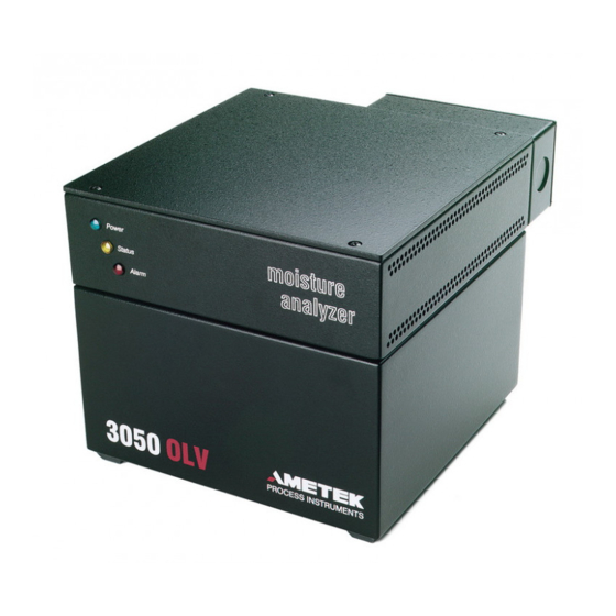
Ametek 3050-OLV Manual Supplement
Moisture analyzer sample system
Hide thumbs
Also See for 3050-OLV:
- User manual (103 pages) ,
- Manual (25 pages) ,
- Manual supplement (12 pages)
Subscribe to Our Youtube Channel
Summary of Contents for Ametek 3050-OLV
- Page 1 Model 3050-OLV Moisture Analyzer Division 2 Sample System Manual Supplement Process Instruments 455 Corporate Boulevard PN 305485001 Rev. L Newark, DE 19702...
- Page 2 © 2000 AMETEK This manual is a guide for the use of the 3050-OLV Moisture Analyzer. Data herein has been verified and validated and is believed adequate for the intended use of this instrument. If the instrument or procedures are used for purposes over and above the capabilities specified herein, confirmation of their validity and suitability should be obtained;...
- Page 3 L’EQUIPEMENT, COUPER LE COURANT OU S’ASSURER QUE L’EMPLACMENT EST DESIGNE NON DANGEREUX. ————————————————————————————————————— All Input and Output Wiring Must be in Accordance with Class I, Division 2 Wir- ing Methods and in Accordance With the Authority Having Jurisdiction. 3050-OLV Division 2 Sample System...
-
Page 4: Power Requirements
(AMETEK PN 571061017 or equivalent). Dry Reference Gas A dryer (AMETEK Dryer PN 305400901S or equivalent) is required to dry reference gas to less than 0.025 ppmv. Dryers must be periodically replaced. In normal use, the dryer (PN 305400901S) should dry a 50-ppm reference gas to specification for 1 year. -
Page 5: Mechanical Installation
Mechanical Installation Locate the 3050-OLV system as close as possible to the sample source. The unit should be protected from direct exposure to weather and sunlight, and located so that the ambient tem- perature specifications will not be exceeded. 1. If not already installed, install a main process shut-off valve and pressure reducer (rec- ommended) at the sample tap. - Page 6 As an example, for Class 1, Division 2, Nema 4(X) outdoor applications, use only gasketed, self-sealing, UL Listed conduit hubs. 3050-OLV Division 2 Sample System...
- Page 7 Figure 1: Sample system fl ow diagram 3050-OLV Division 2 Sample System...
- Page 8 Figure 2: Sample System Wiring Diagram 3050-OLV Division 2 Sample System...
- Page 9 2. Cable shields should be connected to both the analyzer and the DCS. If this is not possible, cable shields should be tied to the chassis at each 3050-OLV. If this is not possible, tie the shield at the PC or DCS to chassis and remaining shield to the chassis through a 0.1 mF @ 500V capacitor.
- Page 10 Figure 3: NEMA Enclosure 3050-OLV Division 2 Sample System...
- Page 11 Terminal Block (Incoming power) Power, 1/2” Gland Liquid Separator (Optional) Signal, 1/2” Gland Communications, 1/2” Gland Back Pressure Regulator (Optional) Power Supply Bypass Outlet 1/4”Tube Sample Outlet 1/8” Tube Figure 4: Sample system components and options 3050-OLV Division 2 Sample System...
- Page 12 Power and signal conduits are on the right side of enclosure. Figure 5: Power and signal conduits Heat trace with thermal switch Terminal block Figure 6: Heat trace and terminal block 3050-OLV Division 2 Sample System...
-
Page 13: Replacement Parts
Replacement Parts Table 1 lists the replacement parts available for the Model 3050-OLV Moisture Analyzer. Please contact the AMETEK Sales office (800-222-6789) for pricing and ordering information. Table 1 Model 3050-OLV Sample System Replacement Parts AMETEK Part Description Part Number... - Page 14 Sample System Options Back Pressure Regulator The 3050-OLV can operate with an exhaust pressure from 0 to 15 psig, and the sensor measure- ments (i.e. - the moisture readings) are automatically compensated for the measured pressure. However, for proper operation of the analyzer, the exhaust pressure that the analyzer sees must remain stable.
-
Page 15: Isolation Valve
AMETEK recommends that an isolation valve is installed upstream of the analyzer, and preferably at the sample tap. Because AMETEK recommends that this valve is installed at the sample tap, we have not included it as part of the sample system package. It is the customer’s responsibility to install a process isolation valve, prior to the installation of the... - Page 16 This page intentionally left blank. 3050-OLV Division 2 Sample System...


Need help?
Do you have a question about the 3050-OLV and is the answer not in the manual?
Questions and answers