
Related Manuals for Ametek 3050-RM


Summary of Contents for Ametek 3050-RM
- Page 1 3050-RM Moisture Analyzer User Manual Process Instruments 455 Corporate Boulevard PN 305892901, Rev R Newark, DE 19702 Configurator Version 3.0...
- Page 2 If the instrument or procedures are used for purposes over and above the capabilities specified herein, confirmation of their validity and suitability should be obtained; otherwise, AMETEK does not guarantee results and assumes no obligation or liability. This publication is not a license to operate under, or a recommendation to infringe upon, any process patents.
-
Page 3: Table Of Contents
Table of Contents CHAPTER 1 3050-RM Moisture Analyzer Overview ......................1-1 Controller / Communications ................1-2 Contact Closure Signals .................1-2 Moisture Sensor .....................1-3 Quartz Crystal Microbalance (QCM) ............1-3 Gas measurement cycle ..................1-3 Gas Flow ......................1-3 Sample system ....................1-3 Sample flow ....................1-4 Solenoid valves ....................1-5 Verifying the Analyzer ...................1-6... - Page 4 Simple Acknowledge ..................5-6 Acknowledge with Data .................5-6 Failure ......................5-6 CHAPTER 6 3050-RM Configurator Software Setup 3050-RM Configurator Software ..............6-1 3050-RM Configurator Software Installation ..........6-1 Configuring the 3050-RM ................6-2 General Tab ......................6-2 PC Communications ..................6-2 Saving Your Settings ..................6-3 Device ......................6-3 Live Data ......................6-3...
- Page 5 Installing the new solenoid ................8-9 Dryers / Contaminant Trap ................8-10 Removing the dryers / contaminant trap .............8-10 Installing the new dryer / contaminant trap ..........8-11 Maintenance of the Electronic Module ............8-12 Removing the Electronic Module from the Model 3050-RM ......8-12...
- Page 6 Tools required ....................8-12 Procedure for removing the electronics module ...........8-12 Analog Interface PCB ..................8-14 Removing the analog interface PCB ............8-14 Replacing the analog interface PCB ............8-14 MCU PCB ......................8-14 Removing the MCU PCB ................8-14 Replacing the MCU PCB ................8-14 Reinstalling the Electronic Module .............8-16 Board Connections ...................8-17 User Interface Board ..................8-17 Spare Parts ....................8-18...
- Page 7 Safety Notes WARNINGS, CAUTIONS, and NOTES contained in this manual emphasize critical instructions as follows: An operating procedure which, if not strictly observed, may result in personal injury or envi- ronmental contamination. WARNING An operating procedure which, if not strictly observed, may result in damage to the equipment. CAUTION ...
- Page 8 Achtung - Heiße Oberfläche Environmental Information (WEEE) This AMETEK product contains materials that can be reclaimed and recycled. In some cases the product may contain materials known to be hazardous to the environment or human health. In order to prevent the release of harmful substances into the environment and to conserve our natural resources, AMETEK recommends that you arrange to recycle this prod- uct when it reaches its “end of life.”...
- Page 9 Electromagnetic Compatibility (EMC) Read and follow the recommendations in this section to avoid performance variations or dam- age to the internal circuits of this equipment when installed in harsh electrical environments. CAUTION The various configurations of the 3050 AM Moisture Analyzer should not produce, or fall victim to, electromagnetic disturbances as specified in the European Union’s EMC Directive.
- Page 10 SPECIAL WARNINGS AND INFORMATION EQUIPMENT USED IN CLASS I, DIVISION 2 HAZARDOUS LOCATIONS This equipment is suitable for Use in Class I, Division 2, Groups ABCD (UL1604/ CSA#213) and general purpose areas only. Explosion Hazard - Substitution of Components May Impair Suitability for Class I, Division WARNING Risque d’explosion - La substitution de composants peut rendre ce materiel inacceptable pour Avertisse-...
- Page 11 | xi...
- Page 12 Process photometric analyzers, process moisture analyzers, and sampling systems are warranted to perform the intended measurement, only in the event that the customer has supplied, and AMETEK has accepted, valid sample stream composition data, process conditions, and electrical area classification prior to order acknowledgment.
-
Page 13: 3050-Rm Moisture Analyzer
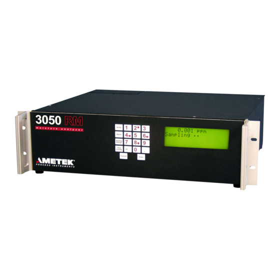
3050-RM MOISTURE ANALYZER Overview The Model 3050-RM Moisture Analyzer reliably measures moisture con- centrations in a variety of industrial and UHP gases, using a quartz crystal microbalance (QCM) sensor. The calibrated range of the analyzer is 0 to 2500 PPMV. The QCM-sensor technology used in this analyzer is com-... -
Page 14: Controller / Communications
One RS-232 or one RS-485 serial interface provides communication be- tween the analyzer and your recording or data acquisition equipment. The Model 3050-RM analyzer is configured, and analyzer parameters are set, by using either the analyzer display, keypad and function keys, or us- ing an external PC. -
Page 15: Moisture Sensor
Moisture Sensor Quartz Crystal Microbalance (QCM) The 3050-RM analyzer uses a quartz crystal microbalance sensor to mea- sure water vapor concentration. This is a piezoelectric device that is capa- ble of extremely sensitive mass measurement. To make the QCM sensitive to water vapor the surface is coated with a thin film of hygroscopic mate- rial. -
Page 16: Sample Flow
Sample flow Normal operation of the Model 3050-RM analyzer uses an internal bypass, which increases the response speed of the system. However, the 3050-RM is capable of running in a gas-saver mode as well, which allows the ana- lyzer to run on a sample volume of approximately 150 SCCM. -
Page 17: Solenoid Valves
The three-way solenoid valves (SV2, SV3, SV4) are used to select the gas stream that is passed through the sensor; the remaining two streams are passed to the vent. In normal operation of the 3050-RM, the analyzer continuously cycles between the sample- and dry-reference gas streams. -
Page 18: Verifying The Analyzer
Dew point values are calculated from the moisture concentration mea- surements (PPMV) and the sample or process pressure. For temperatures below 0 °C, the 3050-RM uses equations to determine the water vapor pressure over ice, rather than over super-cooled water. Thus, the 3050-RM reports a frost-point temperature consistent with the physical form of the condensed phase in a real process stream. - Page 19 GERG-Water Correlation: GERG Technical Monograph TM14, 2001), AMETEK has provided a means of using either method in the 3050-RM product. Specifically, in the gas list we have cited two separate entries for natural gas. The first entry is labeled “Natural Gas”, and will provide dewpoint/frostpoint values consistent with ASTM D1142.
- Page 20 This page intentionally left blank. 1-8 | 3050-RM Moisture Analyzer...
-
Page 21: Chapter 2 Specifications
SPECIFICATIONS All specifications subject to change without notice. NOTE Compatible Gases Air, argon, Air, argon, butane, carbon dioxide, ethane, ethene, Freon 12, Freon 22, Freon 32, Freon 114, Freon 116, Freon 125, Freon 134A, Freon 152, helium, hydrogren, krypton, natural gas, neon, nitrogen, oxygen, pro- pane, propene, SF6, and xenon. - Page 22 [Optimal performance in low-level applications is obtained when ambient tempera- ture is maintained at a constant temperature (± 2 °C)] 90% RH maximum, noncondensing IEC Pollution Degree 2 Maximum altitude 2,000 meters (6560 feet) IEC Installation Category II Indoor use only, IEC 529; IP40 2-2 | 3050-RM Moisture Analyzer...
- Page 23 Utility Requirements 100-127 VAC 47-63 Hz, 185 W max OR 220-240 VAC, 47-63 Hz, 185 W max Mounting 19-inch rack Dimensions Width: 48 cm (19 inches) Height: 13 cm (5.25 inches) Depth: 42 cm (16.5 inches) Net Weight 10.9 Kg (24 lb.) Approvals and Certifications MET Certified to UL/CSA General Safety Requirements -...
- Page 24 This page intentionally left blank. 2-4 | 3050-RM Moisture Analyzer...
-
Page 25: Chapter 3 Installation And Start-Up
INSTALLATION AND START-UP Read this entire chapter before installing the 3050-RM analyzer. Failure to do so may impair protection against fire, electric shock and injury originally provided by this equipment. Do not use this ana- WARNING lyzer in a manner not specified in this manual. -
Page 26: Analyzer Requirements
Analyzer Requirements Space Requirements The 3050-RM Moisture Analyzer requires an area 48 cm wide x 13 cm high x 42 cm deep (19” x 5.25” x 16.5”) plus rear clearance for analyzer connec- tions and proper ventilation (Figures 3-1a, b and c). It should be located as close to the sample tap as possible. - Page 27 Figures 3-1c. Model 3050-RM dimensions top and sides. Installation & Start-Up...
-
Page 28: Utility Requirements
Utility Requirements Electrical requirements The 3050-RM Moisture Analyzer must be installed in a general purpose or Division 2 area. It does not have an On/Off power switch so power must be applied through a circuit breaker switch at the AC source. -
Page 29: Analyzer Installation
Optimal results are obtained with the sample line maintained at 60 °C. Recommended sample gas input tubing is 1/8 inch OD, electro polished 316L VAR stainless steel (AMETEK #257707000 or equiva- lent). Exhaust pressure must be 0 – 15 PSIG. -
Page 30: Rear Panel Connections And Interface Board
Figure 3-2. Model 3050-RM rear panel connections and inside of dryer compartment. Rear Panel Connections and Interface Board See Figures 3-2 and 3-3 for location of analyzer connections on rear panel and interface board. Remove terminal cover to access interface board. - Page 31 Analog Output 4 to 20 mA output to user recording equipment. Wiring supplied by user. Alarm Contacts Connections for: Data Valid, Concentra- tion Alarm and System Alarm. Wiring supplied by user. Figure 3-3. Model 3050-RM interface board connections. Installation & Start-Up...
-
Page 32: Installing The Dryer (Figures 3-4A And B)
Installing the Dryer (Figures 3-4a and b) Prior to operating the 3050-RM analyzer, the dryer must be installed. A dryer is supplied with this analyzer. Make sure that you have the new dryer and the new VCR gaskets available before beginning installation. - Page 33 Remove the dryer mounting screws that holds the dryer in place and set them aside. Working with one dryer at a time to minimize the time that the device is exposed to room air, remove the first dryer from its packaging. Loosen the 1/8 inch VCR fittings.
-
Page 34: Gas Connections (Figure 3-5)
Connect the sample input tube to the analyzer sample inlet. Connect the exhaust tube to the analyzer exhaust. The exhaust must be vented to an appropriate vent system. Check all sample input and exhaust fittings for leaks. Figure 3-5. 3050-RM rear panel gas connections. 3-10 | 3050-RM Moisture Analyzer... -
Page 35: Electrical Connections (Figure 3-6)
WARNING available, contact AMETEK service. Voltage selection The 3050-RM analyzer comes from the factory set to operate on 120 VAC. If you must switch the setting to 240 VAC (or back to the 120 VAC setting), follow the procedure below. -
Page 36: Power Connection
If the new cord is a smaller diameter than the original, consider using the alternate bushing that is included with the European cord. Ensure that the power cord does not slip when pulled or pushed from the outside. 3-12 | 3050-RM Moisture Analyzer... -
Page 37: Communication Connections (Figure 3-9)
Replace rear cover. 10. Reconnect power. Figure 3-9. Communication connections on the 3050-RM analyzer interface board. Communication Connections (Figure 3-9) Disconnect the power from the analyzer and remove the rear panel terminal cover. Connect the 4 to 20 mA analog output (13) (see Figures 3-10a and 3-10b) and alarm and data valid terminals (14) on the interface board to the analyzer through the metallic signal conduit (2) (Figure 3-2). -
Page 38: Rs-485 Communications
Turn on the RS-485 termination switch (11) Figure 3-9 if communi- cating with one analyzer or the last in a chain of analyzers. 2-wire and 4-wire mode selection is performed using software. NOTE 4. Replace terminal cover. 3-14 | 3050-RM Moisture Analyzer... -
Page 39: Signal Connections (4 To 20 Ma )
Signal Connections (4 to 20 mA ) Figure 3-10a. Self-powered 4-20 mA output connections. Figure 3-10b. Externally powered 4-20 mA output connections. Installation & Start-Up 3-15... -
Page 40: Overview Of Keypad
Overview of keypad The Model 3050-RM Moisture Analyzer keypad (Figure 3-11) is used to ac- cess menus and sub-menus and system values for the function keys, and to set-up your analyzer parameters. Figure 3-11. 3050-RM analyzer keypad. Function keys Press one of the four function keys to access the main menu for that cat- egory as well as sub-menus and system values. -
Page 41: Overview Of Display
To highlight an item, scroll through the menu items until the small arrow- heads point to your choice as shown in Figure 3-12. Up and down arrow symbols displayed on the right-hand side of the screen indicate that there are more menu items above or below the currently displayed items. Figure 3-12. -
Page 42: Initial Start-Up
If the concentration value is still decreasing after the initial dry down period, allow additional dry down time. NOTE The 3050-RM Moisture Analyzer is now fully operational with factory default configuration of the analog output and concentration alarms. 3-18 | 3050-RM Moisture Analyzer... -
Page 43: Chapter 4 User Interface
Line 1 - Concentration Heartbeat 5.7 ppmv Sampling . . . Line 2 - Status message High Concentration 5.0 ppmv Limit Line 3 - Alarm message Line 4 - Alarm value Figure 4-1. Keypad and display for the 3050-RM Moisture Analyzer. User Interface... - Page 44 Figure 4-2. Menu map for 3050-RM Moisture Analyzer. 4-2 | 3050-RM Moisture Analyzer...
-
Page 45: Verify Key
Verify Key Use the Verify Key to define on-demand verifysettings. VERIFY Hold Outputs Enable Disable Adjust Span Enable Disable Verify Abort Figure 4-3. Main menu for the Verify key. Hold Outputs Enable Select this function to hold the output at the last valid reading during a verify. -
Page 46: Alarm Key
High Limit Enter the high limit value in moisture units selected. Low Limit Enter the low limit value in moisture units selected. Enable Alarm Select Enable or Disable to activate the moisture concentration alarm relay. 4-4 | 3050-RM Moisture Analyzer... -
Page 47: Range Key
Range Key Use the Range Key to define your 4 to 20 mA output setting. RANGE Enter Maximum Conc Value Enter Minimum Conc Value Figure 4-5. Main menu for Range key. Use this setting to scale the 4 to 20 mA output. The 4 to 20 mA output is proportional to the moisture readings. -
Page 48: Config Key
Select On or Off. The default is ON. Enter Value Contrast 1 to 9 • Font Back Light This is a factory-set parameter that identifies Enter Value the type used for the display on the ana- Font 0 or 1 lyzer. 4-6 | 3050-RM Moisture Analyzer... -
Page 49: Communication
Communication Select communication setup. Config Communication Node Enter Address Address 9600 Baud Rate 19200 RS-485 Two Wire Mode Four Wire optional Node Address Enter the address for RS485 serial communications ( 0 - 240). Address 240 is reserved (see the “Special Addresses” section in Chapter 5 for details). Baud Rate Select the baud rate at which you transfer data (9600 or 19200). -
Page 50: Sample Gas
Gas K Factor. The Gas K Factor is a parameter used by the mass flow meter in the Model 3050-RM to adjust for the molar heat capacities of dif- ferent gases. Nitrogen is used as the reference gas for the K factors, and its value is defined as 1.000. - Page 51 1.395, rather than the 1.401 estimated in the example. Please consult AMETEK Process Instruments for assistance, before run- ning gases that are not listed in the menu on the 3050-RM analyzer. If a custom gas is entered, the conversion to units of dew point will be based on an ideal gas model, without any enhancement factor.
-
Page 52: Clock
Enter the 2-digit value for the month. Wednesday Month Enter Value Thursday Friday Hour Saturday Hour Enter Value Enter the value using the 24-hour clock. Minute Enter Value Minute Enter the 2-digit value for minutes. 4-10 | 3050-RM Moisture Analyzer... -
Page 53: Verify Schedule
After this start-up period, the analyzer NOTE will have dried down sufficiently to increase the verification interval to 1 month. AMETEK recommends that the duration of the verifica- tion cycle be set to 30 (i.e. - 30 minutes). User Interface... - Page 54 Use caution, as entering a “new” value informs the analyzer that a new dryer has been installed in the reference leg of the analyzer. The NOTE remaining dryer capacity is reset when a new number is entered. 4-12 | 3050-RM Moisture Analyzer...
- Page 55 Moisture Units Config PPMV Moisture Unit Select Unit Cen grade Pressure (KPa)* Fahrenheit Pressure (KPa)* lbs/mmscf mg/Nm3 ppm W Select Units The units for the moisture readings can be selected from a list. Pressing Enter at the “Select Units” prompt displays the list. (If a dew/frost point is selected, you must enter a value for the process pressure in units of kPa.
-
Page 56: System Test
Test Analog Output Tests the analog output by allowing the user to set outputs to 4, 12 or 20 mA. Test Serial Communications Performs a “loop back” test and reports the result to the display. 4-14 | 3050-RM Moisture Analyzer... -
Page 57: Chapter 5 Serial Communications
SERIAL COMMUNICATIONS Protocol The protocol used for the 3050-RM Moisture Analyzer is a master/slave, command/response communication with the master initiating all trans- fers. The message format for transfers initiated by the master is seen in Figure 5-1. Figure 5-1. Message format for transfers initiated by the master. - Page 58 The message format for slave acknowledge without a data field is seen in Figure 5-3 . Figure 5-3. Message format for slave acknowledge. The message format for slave failure response is seen in Figure 5-4. Figure 5-4. Slave failure response format. 5-2 | 3050-RM Moisture Analyzer...
-
Page 59: Special Addresses
Special Addresses Addresses $F0 through $FF are reserved for special functions with address $F0 used as a broadcast address. Address $F0 Node address $F0 is used as a single point address, i.e. it is intended for use in configurations with a single slave. The slave will respond to all messages with node address $F0. -
Page 60: Echo (A)
Figures 5-7a and 5-7b for a list of defined handles for system variables. Example Master: >34F0512[CR] Slave: A1234540[CR] Start Verify (G) Initiates a verify cycle. Example: Master: >34G??[CR] (Note the use of wildcard in place of checksum) Slave: A[CR] 5-4 | 3050-RM Moisture Analyzer... -
Page 61: Write Data (H)
Write Data (H) The data field of this frame contains the handle for a system variable. See Figures 5-7a and 5-7b for a list of defined handles for system variables. Example Master: >34H05123.40C[CR] Slave: A[CR] Write Cell EEPROM (L) Copy cell serial number and cell calibration coefficients into cell EEPROM. Example Master: >34LB3[CR]... -
Page 62: Defined Responses (Slave To Master)
‘ A ’ followed by data and checksum. Example: Slave: A0123456A6[CR] Failure All failure responses consist of an ASCII ‘N’ followed by a two byte hexa- decimal ASCII failure code. Defined failure codes are given in the table below. Example: Slave: N01[CR] 5-6 | 3050-RM Moisture Analyzer... - Page 63 Figure 5-6. Defined Failure Codes. Serial Communications...
- Page 64 Figure 5-7a. Variable Table. 5-8 | 3050-RM Moisture Analyzer...
- Page 65 Figure 5-7b. Variable Table. Serial Communications...
- Page 66 This page intentionally left blank. 5-10 | 3050-RM Moisture Analyzer...
- Page 67 Follow the instructions on the subsequent screens to complete the in- stallation. When you get to the Setup Complete screen, click Finish to complete the installation. The default location for the UHP software is in the AMETEK, Inc. folder. Turn off all power saving modes.
-
Page 68: Configuring The 3050-Rm
NOTE serial port settings. PC Communications Click the Setup button to configure PC Communications. The Serial Port Communication screen opens (Figure 6-2). Figure 6-2. PC Serial Communications setup screen. 6-2 | 3050-RM Moisture Analyzer... -
Page 69: Saving Your Settings
Port Select the COM port on your computer where the connection to the analyzer is installed. Baud Rate Select the baud rate at which data will be transferred. RS-232 Port Click if the analyzer is connected to an RS-232 port. RS-485 Port Click if the analyzer is connected to an RS-485 port. -
Page 70: Status
For initial setup of PC communication parameters, use the Setup button on the General tab. NOTE Configuring Multiple Analyzers Use the Device Communications tab to set the analyzer’s communication parameters to agree with the PC settings when controlling analyzers in a daisy chain. 6-4 | 3050-RM Moisture Analyzer... -
Page 71: Changing Communication Parameters
Changing Communication Parameters • Change the ANALYZER parameter(s) first. • Click Apply to confirm the change. This may cause the analyzer to go off-line. • Change the PC settings or physical wires/cables. • Reset the analyzer by recycling power. Figure 6-3. Device Communications setup screen. -
Page 72: Setup Tab
Check this box to enable the concentration alarm. High Limit Enter the high limit for the concentration alarm. Low Limit Enter the low limit for the concentration alarm. To Save settings on the Setup tab, click Apply. 6-6 | 3050-RM Moisture Analyzer... -
Page 73: Schedule Tab
Schedule Tab Use the Schedule tab to schedule routine Zero. Figure 6-5. Schedule tab. Abort Button Click to terminate verification or zero. Verify Now Button Click to begin verify cycle now. Adjust Span check box Checked The analyzer performs a span adjustment at the end of the verify cycle. -
Page 74: Set Moisture Generator Production Code
Saving Your Settings To save settings on the Schedule tab, click Apply. To save settings and exit the program, click Apply+Exit. To abort changes you have made, click Cancel+Exit. This will close the Configurator software program. 6-8 | 3050-RM Moisture Analyzer... -
Page 75: Status Tab
Status Tab Use the Status tab to view current readings and the status of the analyzer. Figure 6-7. Status tab. Upload Data Click Upload Data to save data from the analyzer to a file. The Save As screen opens so that you can browse to where you want to save the file. The file format is Excel-compatible CSV format. -
Page 76: Data Collection
Rate The preferred data collection rate is “0.5” minutes and is set as the default. A record is created every 30 seconds. The collection rate can be increased to one minute or more. 6-10 | 3050-RM Moisture Analyzer... -
Page 77: Chapter 7 Troubleshooting
TROUBLESHOOTING Alarms Following is a table of alarm messages (Figure 7-1) for the AMETEK 3050- RM Moisture Analyzer. If there is a problem, the alarm will appear on the LCD screen on the third and fourth line. Troubleshooting... - Page 78 This page intentionally left blank. 7-2 | 3050-RM Moisture Analyzer...
-
Page 79: Chapter 8 Service And Parts Parts Replacement
SERVICE AND PARTS Parts Replacement Make sure that power has been disconnected from the analyzer before attempting to remove or replace any of the parts. CAUTION Figure 8-1. Model 3050 RM exploded view. Service & Parts... - Page 80 Figure 8-2. Sample System Model 3050 RM. Figure 8-3. Sensor removal in Model 3050 RM. 8-2 | 3050 RM Moisture Analyzer...
-
Page 81: Sensor
Sensor Removing the sensor Remove the top cover from the analyzer. Remove the cover from the oven assembly. Facing the front of the Model 3050 RM analyzer, the sensor is the small PC board with two metal cans in the center of the sample manifold plate (Figure 8-2). Disconnect the two 1/16”... -
Page 82: Mass Flow Meter
Remove the top cover from the analyzer. Remove the cover for the oven assembly. Facing the front of the Model 3050-RM analyzer, the mass flow meter is the small black box on the left-hand side of the sample oven (Figure 8-2). - Page 83 Reconnect all four 1/16 fittings on the bracket in the center of the oven. Replace the oven lid, and secure it with the two nuts. Replace the analyzer cover, and secure it with the mounting nuts. Figure 8-4. Model 3050 RM Mass flow meter.
-
Page 84: Moisture Generator
Remove the top cover from the analyzer. Remove the cover for the oven assembly. Facing the front of the 3050-RM analyzer, the moisture generator is located left- center on the sample manifold plate, above the pressure transducer, between the flowmeter and the sensor assembly. See Figure 8-2. -
Page 85: Installing The New Moisture Generator
Note the position of the moisture generator in the bracket and how it is oriented to the mounting screws and the gas connections. NOTE Remove the old generator from the bracket, and set it aside. Use caution when disconnecting the moisture generator and pressure transducer from the sample system. -
Page 86: Solenoid Valves
Solenoid Valves Remove the top cover from the analyzer. Remove the cover for the oven assembly. Disconnect the 1/16 inch fittings on all four sample tubes, which are located on the bracket in the center of the sample oven (Figure 8-7a). Remove the four nuts that secure the sample manifold plate (the square aluminum mounting plate, located in the front section of the oven), and gently lift the manifold out of the oven (Figure 8-5). -
Page 87: Installing The New Solenoid
Using a flat-head screwdriver, remove the screws that hold the valve body to the manifold; set the screws aside. Lift-off the solenoid valve and reserve the O-rings for the replacement solenoid. Installing the new solenoid Carefully, mount the new solenoid valve on the valve manifold using the two flat-head screws. -
Page 88: Dryers / Contaminant Trap
Dryers / Contaminant Traps Removing the dryers At the rear of the analyzer, locate the dryer compartment on the right- hand side (Figure 8-8). Use a 7/64” hex wrench to loosen the four captured screws on the compartment cover. Remove the cover from the analyzer. The single dryer is located in the bottom position. -
Page 89: Installing The New Dryer / Contaminant Trap
Installing the new dryer / trap Minimize the time that the dryer is exposed to the atmosphere after removing the protective caps. AMETEK recommends that the dryer CAUTION be exposed for less than a minute. Insert the replacement dryer into the dryer port on the analyzer. Use the new gaskets provided with the dryer in each of the fittings. -
Page 90: Maintenance Of The Electronic Module
Maintenance of the Electronic Module The electronics module was designed to easily identify and service the boards and power supplies used in the Model 3050 RM Analyzer. These components include: • MCU Assembly • Analog Interface Assembly • Power Supply •... - Page 91 Figure 8-9. Electronic Module Service & Parts 8-13...
-
Page 92: Analog Interface Pcb
Analog Interface PCB The Analog Interface PCB (AMETEK Part #591210901) is located on top of the MCU PCB at the front of the electronic module (Figure 8-9). Removing the analog interface PCB • Remove the four knurled screws that hold the board in place. - Page 93 Sensor LCD Display Front Panel Thermistor Sensor LCD Display Front Panel Single Fan and Dual Fan DC Power System Alarm DC Power System Alarm (Single) (Dual) Figure 8-10. Analog Interface Board Connections Battery (Solder Side) RS-232 RS-485 RS-485 P3-1 Reference Valve P3-3 Sample Valve RS-232...
-
Page 94: Reinstalling The Electronic Module
Reinstalling the Electronic Module Once you have serviced the various components in the electronics module, reassemble the analyzer. Carefully reposition the electronic module above and to the front of the analyzer. Lower the module into the analyzer so the screws at the four corners can be attached. -
Page 95: Board Connections
Board Connections User Interface Board Heater Wire 120 Volt System RS-485 Alarm 120-Volt System Alarm RS-485 Heater Wire Circuit Side 120-Volt RS-485 System Alarm Service & Parts 8-17... -
Page 96: Spare Parts
Spare Parts Battery, Lithium 280750043 Fuse, 2 Amp, 250V 271291001 LCD Display with 6-inch cable 591132901 MCU Board 305110907S MFM - Mass Flow Meter 305449901S PCB Assembly, Analog Interface 591144901 PCB Assembly, User Interface 591200901 Power Supply (+/-15 V, 5V) T460-048 Power Supply (24 V) 271768001... - Page 97 QUICK REFERENCE CARD Reference Chapter 3 of the 3050-RM Moisture Analyzer manual. INSTALLATION AND START-UP ANALYZER PARAMETERS Incoming sample temperature 0 °C and 100 °C Optimum input gas temperature 60 °C ± 5 °C Verify Key: Minimum input pressure 20 PSIG...
- Page 98 PPmV Centigrade Fahrenheit lbs/mnscf mg/Nm ppmW...
Need help?
Do you have a question about the 3050-RM and is the answer not in the manual?
Questions and answers