Ametek 3050-OLV User Manual
Moisture analyzer
Hide thumbs
Also See for 3050-OLV:
- Manual supplement (16 pages) ,
- User manual (46 pages) ,
- Manual (25 pages)

Related Manuals for Ametek 3050-OLV


Summary of Contents for Ametek 3050-OLV
- Page 1 USER MANUAL 3050-OLV Moisture Analyzer PN 305200901, Rev YT AMETEK 3050 Configurator Software Version 2.0...
- Page 2 AMETEK Process Instruments assumes no responsibility or liability for any errors or inaccuracies that may appear in this document. AMETEK Process Instruments is not responsible for any infringement of patents or other rights of third parties that may result from the use of this document. The content of this document is furnished for informational purposes only, is subject to change without notice, and does not represent a commitment or guaranty by AMETEK Process Instruments.
-
Page 3: Table Of Contents
Tools, Equipment, and Supplies Required for Installation ..........2-4 Mechanical Installation .........................2-6 Dryer Installation Instructions ....................2-9 Electrical Connections ........................2-11 3050-OLV Power and Signal Connections ................2-12 Power Connections ......................2-12 Signal Connections ......................2-12 4–20 mA Output Wiring ......................2-13 RS-232 Wiring ..........................2-14 RS-485 Cables, Multiple 3050-OLV Analyzers .............. - Page 4 Frequency Offset ..........................4-19 Span Factor ............................ 4-21 Alarm and Warning Messages ......................4-22 SPECIFICATIONS ........................5-1 3050-OLV Moisture Analyzer Specifications .................5-1 3050-OLV Moisture Analyzer Approvals and Certifications.............5-2 3050-OLV Moisture Analyzer Rating Label ..................5-2 PN 305200901, Rev YT iv | 3050-OLV Moisture Analyzer...
- Page 5 SERIAL COMMUNICATION INTERFACE (MODBUS ® ) ............6-1 Analyzer Modbus Interface Parameters ..................6-3 Modbus Address ..........................6-3 Communication Parameters .......................6-3 Modbus Functions ..........................6-4 Exception Code..........................6-4 Holding Registers ..........................6-5 ID/Status Information ......................... 6-10 Analyzer Configuration Operations ..................6-11 Configuration Examples .....................6-11 Example 1: Alarm Enable....................6-11 Example 2: Setting the High Alarm Limit ..............6-11 Example 3: Setting the Low Alarm Limit ..............6-12 Example 4: Enabling “Hold During Verify”...
-
Page 6: Safety Notes
Burn hazard. Hot surface. Do not touch, allow to cool before servicing. Read this manual before beginning the installation and operation of the 3050-OLV Analyzer system. Failure to do so, and/or use of the equipment in a manner not specified in this manual or accompanying documents, may impair the protection against fire, electrical shock and injury originally provided by this equipment. -
Page 7: Personnel And Equipment Safety Information
Personnel and Equipment Safety Information This section describes important safety information to avoid personal injury and dam- age to the equipment while installing, operating, maintaining, or servicing the equip- ment. All safety regulations, standards, and procedures at the analyzer location must be followed. - Page 8 Do not operate this product from a power source that applies more than the voltage specified. Do Not Operate with Suspected Failures If you suspect there is damage to this product, have it inspected by qualified service personnel. PN 305200901, Rev YT viii | 3050-OLV Moisture Analyzer...
-
Page 9: Important Notice To Users
Wiring Methods (NEC Sec 501.4(b) or CEC 18-152) and in Accordance with the Authority Having Jurisdiction. If the 3050-OLV is to be powered by a source of 24 VDC other than that supplied by AMETEK, the power source’s output must be isolated from hazardous mains voltages by use of double or reinforced insulation, having a minimum dielectric strength 2300 VAC. -
Page 10: Electromagnetic Compatibility (Emc)
The various configurations of the 3050-OLV Analyzer should not produce, or fall victim to, electromag- netic disturbances as specified in the European Union’s EMC Directive. Strict compliance to the EMC Directive requires certain installation techniques and wiring practices be used in order that erratic behavior of the Analyzer, or its electronic neighbors be prevented or minimized. -
Page 11: Warning Labels
Achtung – Heiße Oberfläche Environmental Information – WEEE This AMETEK product contains materials that can be reclaimed and recycled. In some cases the product may contain materials known to be hazardous to the environ- ment or human health. In order to prevent the release of harmful substances into the environment and to conserve our natural resources, AMETEK recommends that you arrange to recycle this product when it reaches its “end of life. - Page 12 This page intentionally left blank. PN 305200901, Rev YT xii | 3050-OLV Moisture Analyzer...
-
Page 13: Overview
Overview The 3050-OLV Moisture Analyzer measures trace concentrations of moisture in a process gas stream. The 3050-OLV is compatible with He, Ar, Ne, Xe, Kr, O , NO, CO, CO , light hydrocarbons, natural gas, refrigerants, air, and specialty gases. Refer to Figure 1-3 for a Gas List. The analyzer is calibrated to measure moisture contents from 0.1–2,500 PPMV. - Page 14 Figure 1-2. 3050-OLV Flow Diagram. 1-2 | 3050-OLV Moisture Analyzer PN 305200901, Rev YT...
-
Page 15: Controller Communication
One RS-232 serial port. • One RS-485 serial port. The 3050-OLV has no local user programming functions. It requires serial communication with an external PC for configuration. Once configured, the analyzer is capable of standalone operation. The analyzer is factory configured and packaged with Configurator Software for initial setup of operating param- eters. -
Page 16: Verification
Verification The 3050-OLV has a built-in Moisture Generator for onboard Verification. A portion of the dry Reference gas flows through the Moisture Generator where a known amount of moisture is added. When Cell Verification is initiated, the QCM sensor is alternately exposed to gas from the Moisture Generator and dry Reference gas. -
Page 17: Dewpoint Conversions
A second consideration, when using the 3050-OLV Analyzer to calculate dewpoint/frostpoint temperatures, is the sample (i.e., the process) pressure. The range of process pressures allowed by the 3050-OLV is restricted for many sample gases. Many gases liquefy at relatively low pressures, so calculating a dewpoint/frostpoint temperature for these compounds has no value. -
Page 18: Calculation Of Dewpoint Values For Hydrocarbon Streams
(ISO 18453, which is based on the work presented in GERG-Water Correlation: GERG Technical Monograph TM14, 2001), AMETEK has provided a means of using either method in the 3050-OLV product. Specifically, in the Gas List we have cited two separate entries for natural gas. The first entry is labeled “Natural Gas”, and will provide dewpoint/frostpoint values consistent with... -
Page 19: 3050-Olv Analyzer Gas List
(ethylene) helium hydrogen krypton methane natural gas natural gas GERG neon nitrogen oxygen propane propene (propylene) R114 xenon Figure 1-3. 3050-OLV Gas List. Contact AMETEK Service with inquiries regarding other applications. Overview PN 305200901, Rev YT... - Page 20 This page intentionally left blank. 1-8 | 3050-OLV Moisture Analyzer PN 305200901, Rev YT...
-
Page 21: Installation And Start-Up
All regulatory agency and personnel safety proce- dures for your jurisdiction must be followed. ”PN” in this chapter refers to AMETEK Part Number. The installation of the analyzer must be in accordance with all of the customer and local regulatory standards and procedures. There are no operator-serviceable components inside the analyzer. -
Page 22: Pre-Installation Requirements
(refer to Chapter 5). If the ambient temperature is outside the specified limits or the vibration is excessive, contact your AMETEK representative to discuss solutions and special options to address ambi- ent temperatures. -
Page 23: Unpacking And Inspecting The Equipment
24 VDC power supply (PN 305442901) with universal input (85–265 V, 47–63 Hz) can be purchased from AMETEK. If the analyzer is powered by a 24 VDC source other than that supplied by AMETEK, the power source’s output must be isolated from hazardous mains voltages by use of double or reinforced insulation having a minimum dielectric strength of 2300 VAC. -
Page 24: Tools, Equipment, And Supplies Required For Installation
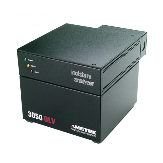
Sample Gases • The 3050-OLV is designed to operate on a clean gas stream; specifically, the Sample gas stream must be free of particulates and aerosols. If the 3050-OLV Analyzer is being used on a clean gas stream (i.e., free from particulates... - Page 25 Power moisture Status analyzer Alarm 18.7 (7.36) 3050 OL V PROCESS INSTRUMENTS 20.32 (8.00) 25.24 (9.56) 4.00 (1.56) 20.32 (8.00) (inches) Figure 2-1. 3050-OLV Analyzer front and side view. Installation and Start-Up PN 305200901, Rev YT...
-
Page 26: Mechanical Installation
Mechanical Installation Install the 3050-OLV Analyzer as close as possible to the sample source. The unit should be protected from direct exposure to weather and located so that the ambient temperature specifications will not be exceeded (see Figure 2-2 for connection locations). - Page 27 1 2 3 4 5 6 7 8 9 1 0 1 1 1 2 TB-1 TB-2 Power Signal Connections Exhaust Sample From 15.04 Dryer Dryer (5.92) 50 PSI MAX 3.81 3.81 (1.50) (1.50) 7.62 7.62 inches (3.00) (3.00) Figure 2-2. 3050-OLV Analyzer rear view. Installation and Start-Up PN 305200901, Rev YT...
- Page 28 To Analyzer* *Depending on application consider heat tracing the sample line. Gauge Optional Heated or Unheated Remote Pressure Regulator Probe Ball Valve Sample Flow Figure 2-3. Typical Probe Installation. 2-8 | 3050-OLV Moisture Analyzer PN 305200901, Rev YT...
-
Page 29: Dryer Installation Instructions
Dryer Installation Instructions Tools needed to install Dryer: • One #2 slotted screwdriver • Two 7/16-inch wrenches • One 5/8-inch wrench • One 3/4-inch wrench 1. To alleviate stress on the tube connections attach the Dryer to the Dryer Bracket using two (2) 10-32 screws, and flat and lock washers (Figure 2-4). 2. - Page 30 Figure 2-4. Dryer Installation. 2-10 | 3050-OLV Moisture Analyzer PN 305200901, Rev YT...
-
Page 31: Electrical Connections
Exhaus t Fr om Sam pl e Dr yer Dr yer 50 PSI M ax Figure 2-5. 3050-OLV Power and Signal Connections, Rear View. Rear View Power Terminal Function DC P ower , 24 +/- 4 Volts 3.15 Amps Fused... -
Page 32: 3050-Olv Power And Signal Connections
3050-OLV Power and Signal Connections Power Connections Terminal Function DC Power, 24 ±4 Volts 3.15 Amps F used DC Common Chassis Ground Signal Connections Terminal Function Remote Pressure Transmitter + Remote Pressure Transmitter Return 4–20 mA Output Source Isolated 24 V power supply +, 50 mA maximum Isolated 24 V power supply 4–20 mA Output Return... -
Page 33: 4-20 Ma Output Wiring
2. Cable shields should be connected to both the analyzer and the DCS. If this is not possible, cable shields should be tied to the chassis at each 3050-OLV. If this is not possible, tie the shield at the PC or DCS to chassis and remaining shield to the chassis through a 0.1 mF @ 500V capacitor... -
Page 34: Rs-232 Wiring
Maximum cable length is 10 metres. (maximum cable length 10m) 9 pin PC connector 3050-OLV (type DB9M) (type DB9F) 25 pin PC connector 3050-OLV Figure 2-7. (type DB9M) (type DB25F) RS-232 Wiring. 2-14 | 3050-OLV Moisture Analyzer PN 305200901, Rev YT... -
Page 35: Rs-485 Cables, Multiple 3050-Olv Analyzers
3. Cable shields should be connected to both the analyzer and the DCS. If this is not possible, cable shields should be tied to the chassis at each 3050-OLV. If this is not Cable shields should be connected to both the analyzer and the DCS. -
Page 36: Rs-485 To Rs-232 Conversion For Host Pc
1. Converter and Power Supply are not suitable for use in hazardous locations. 2. Refer to Chapter 4 for replacement part numbers. Converter and Power Supply are not suitable for use in hazardous locations. Refer to Chapter 4 for replacement part numbers. 2-16 | 3050-OLV Moisture Analyzer PN 305200901, Rev YT... -
Page 37: Analyzer Start-Up
Analyzer Start-up 1. Turn On the power source. 2. Open main process shut-off valve. Adjust sample pressure between 20–50 PSIG. Allow the analyzer to dry down before recording moisture concentra- tion measurements. Dry Down Period Allow a minimum of two (2) hours for the analyzer to dry down and stabilize. For sample systems, allow a minimum of three (3) days. - Page 38 This page intentionally left blank. 2-18 | 3050-OLV Moisture Analyzer PN 305200901, Rev YT...
-
Page 39: Controller/Interface
3. Follow the instructions on the subsequent screens to complete the in- stallation. When you get to the Setup Complete screen, click Finish to complete the installation. The default location for the 3050 Configurator Software is in the AMETEK folder. Controller/Interface PN 305200901, Rev YT... -
Page 40: Configuring The 3050-Olv Analyzer
Device Communication tab. These changes must be made before you make any changes to the computer serial port settings. Figure 3-1. General tab. 3-2 | 3050-OLV Moisture Analyzer PN 305200901, Rev YT... - Page 41 PC Communications Displays information that has been configured from the Communication Settings dialog box. Setup Allows you to set up the communication parameters required to establish communication with the analyzer (see “PC Communications Setup Options” in this chapter). Click the Setup button to view the serial port Communication Set- tings dialog box, where you can configure PC Communications (Figure 3-2).
-
Page 42: Saving The Settings On The General Tab
To save settings on the General tab, click Apply. To discard the changes you have made, click Cancel. This will close the 3050 Configurator Software program. Clicking OK or Cancel will close the 3050 Configurator Software. 3-4 | 3050-OLV Moisture Analyzer PN 305200901, Rev YT... -
Page 43: Pc Communications Setup Options
Using this option allows for remote communica- tion between the analyzer and the customer DCS, DAS, or PLC. When changing from AMETEK Serial to Modbus Serial or Modbus TCP, the analyzer communication parameters must be changed be- fore the computer serial port settings. -
Page 44: Ametek Serial Communication Setup
AMETEK Serial Communication Setup When you select the AMETEK Serial communication option (Figure 3-2.1), the following parameter settings are available: Settings Port Select the COM port on your computer where the connection to the analyzer is installed. Baud (Rate) Select the baud rate at which data will be transferred. -
Page 45: Modbus Serial Communication Setup
Time out (ms) Time out value (duration) that the software will use to attempt to establish communications with the analyzer. AMETEK recommends a value of 1000 ms. Stop Bits Select the number of stop bits (1 or 2) of the Modbus network. -
Page 46: Modbus Tcp Communication Setup
Time out (ms) Time out value (duration) that the software will use to attempt to establish communications with the analyzer. AMETEK recommends a value of 1000 ms. Saving the PC Communication Settings To save the settings from any of the PC Communications settings screen, click To discard the changes you have made, click Cancel. -
Page 47: Working From The Device Communication Tab
Working From the Device Communication Tab For initial setup of PC Communications parameters, click the Setup button on the General tab. Configuring Multiple Analyzers Use the Device Communication tab (Figures 3-3.1 and 3-3.2) to set the ana- lyzer’s communication parameters to agree with the PC settings when control- ling analyzers connected in a daisy chain. - Page 48 The 3050 Analyzer can only operate at the four combinations listed below. Parity Stop Bits Even None None Figure 3-3.1. Device Communications setup screen for AMETEK Serial. Figure 3-3.2. Device Communications setup screen for Modbus Serial. 3-10 | 3050-OLV Moisture Analyzer PN 305200901, Rev YT...
-
Page 49: Saving The Settings On The Device Communication Tab
Saving the Settings on the Device Communication Tab To save settings on the Device Communication tab, click Apply. To discard the changes you have made, click Cancel. This will close the 3050 Configurator Software program. PC Communications Once the Device (analyzer) communication settings have been changed, the PC Communications setup screen will automatically open. -
Page 50: Working From The Setup Tab
Select this if using a fixed input. If selected, you must enter a fixed value. External Select this if using an external input. If selected, you must enter values for 20 mA and 4 mA points. Absolute pressure is required. 3-12 | 3050-OLV Moisture Analyzer PN 305200901, Rev YT... -
Page 51: Saving The Settings On The Setup Tab
Sensor Saver Select this check box to enable Sensor Saver. Checked Analyzer operates with a slow cycle time, maxi- mizing Measuring Cell life at the expense of system response time. Not Checked Analyzer operates with a rapid cycle time, mini- mizing system response time. -
Page 52: Working From The Verification Tab
The analyzer performs only a Verification. Ignore span drift Checked One time Span value change is not limited. Not Checked One time Span value change is limited to 10 % of the existing Span value. 3-14 | 3050-OLV Moisture Analyzer PN 305200901, Rev YT... - Page 53 Set Dryer Production Code Click to enter the Dryer Production Code for the Dryer that is installed in the analyzer. Click OK to accept. You must enter a new Dryer code each time you replace the Dryer. Figure 3-6.2. Dryer Production Code entry dialog box.
-
Page 54: Saving The Settings On The Verification Tab
Saving the Settings on the Verification Tab To save settings on the Verification tab, click Apply. To discard the changes you have made, click Cancel. This will close the 3050 Configurator Software program. 3-16 | 3050-OLV Moisture Analyzer PN 305200901, Rev YT... -
Page 55: Viewing Live Data From The Status Tab
Viewing Live Data From the Status Tab Use the Status tab to view current readings and the status of the analyzer. Figure 3-7. Status tab. Controller/Interface 3-17 PN 305200901, Rev YT... -
Page 56: Working From The Monitor Tab
Press the Off button to stop data collec- tion. The file will close when the Off button is pressed or another configurator button is selected. If you exit the Monitor tab, the Data Capture will automatically terminate. 3-18 | 3050-OLV Moisture Analyzer PN 305200901, Rev YT... - Page 57 Figure 3-8.2. Save As dialog box, Monitor tab. Rate The preferred data collection rate is “0.5” minutes (factory-set default). A record is created every 30 seconds. The collection rate can be increased to one (1) minute or more. Flow Adjust Flow Adjust is a utility designed to calibrate the internal flow meter inside the 3050 Analyzer.
- Page 58 The Test Alarms buttons allow you to toggle the alarm contacts to an Opened or Closed state. Use a multi-meter set to ohms to read resistance. Refer to Figure 2-5 and to “3050-OLV Power and Signal Connections” in Chapter 2 for the analyzer contact locations.
- Page 59 Test mA Output The Test mA Output buttons allow you to test the analog outputs. Use a meter while testing the outputs. Refer to Figure 2-6 for wiring. To exit out of Test mode, click another button. Test mode will automati- cally time out after 10 minutes of inactivity.
- Page 60 This page intentionally left blank. 3-22 | 3050-OLV Moisture Analyzer PN 305200901, Rev YT...
-
Page 61: Maintenance And Troubleshooting
Always use gloves when working on the analyzer. This chapter assumes that you have installed the AMETEK 3050 Configurator Software program and that you are using the program to troubleshoot the analyzer. This chapter only addresses troubleshooting the black box (electron- ics unit inside the cast enclosure) problems and not any external sample sys- tem problems. -
Page 62: Aftermarket Excellence And Long-Term Commitment To Safety And Quality
Aftermarket Excellence and Long-Term Commitment to Safety and Quality Safety is a core value at AMETEK Process Instruments and is our primary consideration in every decision. We believe all accidents, injuries, and occupa- tional illnesses are preventable. We adhere to the highest design and safety... -
Page 63: Requesting Technical Support
Requesting Technical Support To request service support, a call back, or product information we encour- age you to use our Web-to-Case online tool, so we are instantly aware of your request no matter the time zone or day of the week. To do this, follow the link below. -
Page 64: 3050-Olv Analyzer Replacement Parts
Solenoid Valves (4) General Services (Viton) 305644901S 4-12 Solenoid Valves (4) Sour Natural Gas (EPDM) 305644902S 4-12 High Capacity Dryer * 305400901S 2-4, 4-11 3050-OLV Moisture Analyzer User Manual 305200901 — MCU Board 305110901S — Cell Interface Board 305113903S 4-4, 4-6... -
Page 65: Diagnostics Charts
Diagnostics Charts While performing many of these checks, it will be necessary to be simultane- ously working with the AMETEK 3050 Configurator Software program running. Pressure Checks Possible Cause Corrective Action Process Pressure set Make sure your inlet sample pressure supply is between incorrectly 1.38–3.45 BARG and stable (or if your unit was created to run at... -
Page 66: Temperature Checks
Check the software parameters to ensure they are set to proper values. • Check the oven’s insulation to ensure it is intact and has no obvious gaps or lack of insulation around the oven walls. 4-6 | 3050-OLV Moisture Analyzer PN 305200901, Rev YT... - Page 67 First, start with checking the software: 1. The software parameters should be accessed using the ALT-C window. Working in the 3050 Configurator Software, view the Setup tab and, using your computer’s keyboard, simultaneously press the “ALT” and “C” keys to display the Command dialog box.
- Page 68 5. Connect your computer to the analyzer and power up the computer, and run the Configurator Software. 6. Apply the required 24 VDC power to the unit. 4-8 | 3050-OLV Moisture Analyzer PN 305200901, Rev YT...
-
Page 69: Oven Sensor Checks
Oven Sensor Checks Temperature problems can be found in various location, as listed under Pos- sible Causes: Possible Causes Corrective Action Cell Detector PC board The Oven Sensor is located on the Cell Detector PC board. The (the sensing device) prob- thermistor is a solid state device on the Cell Detector PC board lems/failure and cannot be replaced. - Page 70 Oven sensor on the cell PC Board Figure 4-4. Oven Sensor location, on Cell Detector PC board. 4-10 | 3050-OLV Moisture Analyzer PN 305200901, Rev YT...
- Page 71 22 AWG FEMALE CONNECTOR HEATER THERMAL SWITCH THERMOSTAT Figure 4-5. 24vdc, 36w HEATER Heater Control Circuit Schematic. Figure 4-6. Cell Interface board (AMETEK PN 305113903S). PN 305200901, Rev YT Maintenance and Troubleshooting 4-11...
-
Page 72: Flow Checks
Flow Checks The 3050-OLV-SLR, -TE, and -DO analyzer black boxes all have an internal Plumbing diagram (Figure 4-7). Figure 4-7. 3050-OLV Internal Plumbing Diagram. Note that there is one common input, Sample In, and one common output, Sample Out. All four vents from the valves are tied to the sample out vent. - Page 73 To turn off (close) the Bypass valve using the 3050 Configurator Software, view the Setup tab and click the Gas Saver check box. Figure 4-8. Setup tab. PN 305200901, Rev YT Maintenance and Troubleshooting 4-13...
-
Page 74: Flow Parameters Verification
ID Numbers 16, 17, 18. These parameters (16, 17, should only be logged and reported to AMETEK if the flow problem cannot be fixed. When contacting AMETEK, also report the Gas that has been chosen or that is displayed in the Gas field on the Setup tab. Whichever Gas is chosen, it has specific Values for ID Numbers 16, 17, 18. - Page 75 If the flow problem clears within 10–20 minutes, replace the exhaust fitting. If the problem persists, the issue is with the exhaust header. You must either find a new exhaust vent or install an AMETEK Process Instruments supplied back pressure regulator. If a back pressure regulator is being used, the differential pressure (delta P) between the inlet and outlet of the analyzer must be main- tained at a minimum of 15 PSIG.
- Page 76 Bad PSV valve, Flow Meter, or both. • Software problem. Software problems on flow are not common, but should be considered and checked. AMETEK will have you check software parameters if needed. 4-16 | 3050-OLV Moisture Analyzer PN 305200901, Rev YT...
- Page 77 Figure 4-11. Flow diagram. PN 305200901, Rev YT Maintenance and Troubleshooting 4-17...
- Page 78 Figure 4-12. Capillaries. 4-18 | 3050-OLV Moisture Analyzer PN 305200901, Rev YT...
-
Page 79: Frequency Offset
Frequency Offset Frequency offset is only used with the 3050-SLR, -TE, and -DO models. The 3050-OLV has no Zeroing method but it is important to be aware of what this parameter is and how it affects the instrument readings. Frequency offset is defined by AMETEK Process Instruments as the amount of Delta Frequency deviation from 0.0 Hz (plus or minus), at the end of the Zero... - Page 80 Zero by increasing this limit and running another Zero. By doing this, you will bring the analyzer back on line (eliminate the alarm), but you will have to replace the defective Dryer as soon as possible. 4-20 | 3050-OLV Moisture Analyzer PN 305200901, Rev YT...
-
Page 81: Span Factor
1.10, the analyzer readings will be 10 % higher. Conversely, by decreasing this factor to 0.9 the analyzer readings will be 10 % lower. AMETEK analyzers leave the factory with Moisture Span set to 1.00. Normal Span Factor numbers in the field will range from 0.5 to 3.00. -
Page 82: Alarm And Warning Messages
Descriptions of the Alarms and Warnings, along with corrective action to take to correct the Error, are also included. If a system alarm is triggered, the RED LED on the front panel of the 3050-OLV Analyzer will flash to signal the source of the problem. The RED LED will flash On for one (1) second and Off for one (1) second. - Page 83 Alarm Condition / Description / Corrective Action Flow Out of Tolerance* Sample flow rate too high or too low. Corrective Action: Check the Inlet and Outlet pressure. Call AMETEK Service if the problem persists. Battery Low* Battery needs to be replaced. Corrective Action: Call AMETEK Service.
- Page 84 This page intentionally left blank. 4-24 | 3050-OLV Moisture Analyzer PN 305200901, Rev YT...
-
Page 85: Specifications
Specifications Specifications included in this chapter are typical for the ranges listed. For custom ranges/applications, or consult with your AMETEK repre- sentative. 3050-OLV Moisture Analyzer Specifications Specification Description Ranges Calibrated 0.1–2,500 parts per million by volume (PPMV) Readings can also be displayed in units of PPMW, lb/mmscf,... -
Page 86: 3050-Olv Moisture Analyzer Approvals And Certifications
Weight of Analyzer 4.2 Kg Minimum PC Windows XP, 7, or 10 Requirements 3050-OLV Moisture Analyzer Approvals and Certifications Approvals and UL/CSA General Safety Requirements (General Purpose) Certifications UL/CSA Class I, Division 2, Groups A, B, C, D T4 UL/CSA Class I, Division 1, Groups B, C, D T5 T6 ATEX/IECEx db eb IIB + H2 T* Gb IP65 T6: -20 to 40 °C... -
Page 87: Serial Communication Interface (Modbus ® )
This program provides a graphical user interface to set up all the analyzer parameters as explained in Chapter 3. The variable called SerialMode allows switching communication protocol from AMETEK ASCII to Modbus protocol and back from Modbus to AMETEK ASCII. This variable can be reached from AMETEK ASCII protocol by ID=38(26Hex) and SerialMode can be modified by modifying holding register #28(4029), as indicated in the holding registers table. - Page 88 Power should be cycled Off-On or a reset command should be issued to activate the change in the serial mode setting. It is strongly recommended to conFigure and to test 3050 Analyzer in AMETEK ASCII mode using user-friendly 3050 Configurator Software. The Modbus RTU protocol mode should be used for monitoring purposes.
-
Page 89: Analyzer Modbus Interface Parameters
Analyzer Modbus Interface Parameters A number of analyzer Modbus interface parameters need to be set up in order to establish communication with the Modbus master. These parameters are accessed via the service port on the analyzer using a service program running on a PC. -
Page 90: Modbus Functions
When the values to be written to holding registers are outside the appro- priate ranges, exception code 03 is returned. 6-4 | 3050-OLV Moisture Analyzer PN 305200901, Rev YT... -
Page 91: Holding Registers
Holding Registers Since the RAM space on the analyzers is limited and not every customer’s DCS\SCADA\DAS\PLC supports Modbus floating point value transfer, floating point values that are commonly accessed on a 3050 Analyzer are scaled and converted into integer values to load into Modbus registers for transmission. The Register values need to be scaled back at the receiving end to yield the actual values. - Page 92 Heater control parameter (uMinLoop2= 23 Hex — 1 r,w — Gas based coefficient (PpmW= 24 Hex) — 1000 r,w — — — Flow control parameter (TempLoopDelay= 29 Hex) second Unit of measurement selection (MoistureUnits= 2B Hex) — 6-6 | 3050-OLV Moisture Analyzer PN 305200901, Rev YT...
- Page 93 DEFINITION UNITS SCALING ACCESS Concentration alarm range (Alarm1Hi= 2C Hex) — Concentration alarm range (Alarm1Lo= 2D Hex) — Concentration alarm range (Alarm2Hi= 2E Hex) — Concentration alarm range (Alarm2Lo= 2F Hex) — Process pressure units (PressUnits= 30 Hex) — Bypass valve state (BypassState= 31 Hex) —...
- Page 94 Dryer production code (DryerDateCode= 79 Hex) — — — 226-228 Reserved — — — Hi Span Limit (HiSpanLimit= 94 Hex) — — — Low Span Limit (LowSpanLimit= 95 Hex) — — — 6-8 | 3050-OLV Moisture Analyzer PN 305200901, Rev YT...
- Page 95 Register #0 holds the moisture concentration value not held during Verifica- tion. This value is in PPM. A pair of registers #135 and #136 provide the same moisture concentration value in floating point Modicon standard. Register #1 holds the moisture concentration value held during Verification. The units of measurement are changing depending of flag status located in register #65.
-
Page 96: Id/Status Information
The Modbus master can poll the analyzer periodically for status information via Modbus function 17 (11Hex). The returned information has the following format: 1 byte Slave ID = 50h for 3050-OLV Analyzer 1 byte Run Status = FFh for Analyzer Online (invalid signal = 0) -
Page 97: Analyzer Configuration Operations
Modbus using the serial communi- cations port. While the 3050 can be completely configured using the Modbus connection, AMETEK recommends the use of the 3050 Configurator Software for configuring the analyzer. The 3050 Configurator Software is compatible with Modbus RTU as well. -
Page 98: Example 3: Setting The Low Alarm Limit
Set the analyzer to operate in the Sensor Write one holding register (function 06). Saver mode. Register address = 99 (holding register #40100). Value = 1 (enable sensor saver =1, disable sensor saver = 0). 6-12 | 3050-OLV Moisture Analyzer PN 305200901, Rev YT... -
Page 99: Example 8: Switch To Dewpoint Readings
Example 8: Switch to Dewpoint Readings Task Actions ACTION 1 Set the analyzer to output the moisture concentration as a dewpoint, using the Write one holding register (function 06). Centigrade scale. A fixed process pressure of Register address = 65 (holding register 150 kPa is used for this example. -
Page 100: Example 9: Selecting A Sample Gas
#40048). Value = 1500Hex (multiplied by the scaling factor of 10). Write one holding register (function 06). Register address = 48 (holding register #40049). Value = 1500Hex (multiplied by the scaling factor of 10). 6-14 | 3050-OLV Moisture Analyzer PN 305200901, Rev YT... -
Page 101: Example 10: Setting Verification Schedule
Example 10: Setting Verification Schedule Task Actions ACTION 1 Set the analyzer to automatically trigger a Verification. For this example, the analyzer Set the Verification type to Monthly. will be set to perform a Verification on the third day of each month, at noon (12:00). Write one holding register (function 06). - Page 102 This page intentionally left blank. 6-16 | 3050-OLV Moisture Analyzer PN 305200901, Rev YT...
- Page 103 AMETEK Process Instruments delivers worldwide sales and service support through a network of direct and factory-trained global distribution channels. AMETEK Service Assistance Program plans offer coverage up to 24 hours a day, 365 days of the year. As worldwide experts in the manufacture of process analyzers and instrumentation, we have supplied solutions to industry since 1962, providing the widest range of analysis technology available.
Need help?
Do you have a question about the 3050-OLV and is the answer not in the manual?
Questions and answers