Advertisement
Quick Links
Instruction Manual
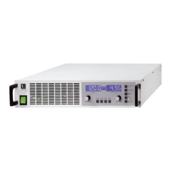
PS 8000 2U
Laboratory Power Supply
本图片为标准2U版产品
操作说明书
/
Picture shows standard 2U version
PS 8032-20 2U:
PS 8065-10 2U:
PS 8160-05 2U:
PS 8080-40 2U:
PS 8080-60 2U:
PS 8080-120 2U:
PS 8160-60 2U:
09 230 130
PS 8360-15 2U:
09 230 131
PS 8360-30 2U:
09 230 132
PS 8720-15 2U:
09 230 133
PS 8040-60 2U:
09 230 134
PS 8040-120 2U:
09 230 135
09 230 136
09 230 137
09 230 138
09 230 139
09 230 144
09 230 145
Advertisement
Chapters

Related Manuals for Elektro-Automatik 09 230130


Summary of Contents for Elektro-Automatik 09 230130
- Page 1 操作说明书 Instruction Manual PS 8000 2U Laboratory Power Supply 本图片为标准2U版产品 Picture shows standard 2U version PS 8032-20 2U: 09 230 130 PS 8360-15 2U: 09 230 137 PS 8065-10 2U: 09 230 131 PS 8360-30 2U: 09 230 138 PS 8160-05 2U: 09 230 132 PS 8720-15 2U: 09 230 139...
- Page 3 一般信息 关于 有生命危险 Elektro-Automatik GmbH & Co. KG 危险电压 Helmholtzstrasse 31-33 本产品输出电压可能上升至危险级别(>60V )! 41747 Viersen 产品上所有带电元件必须有外遮盖。输出端的所有操作必须在 Germany 产品与主电源(电源开关关闭)断开时才能执行,且可只有受 电话: +49 2162 / 37850 训过电流危险知识的专业人员执行此类操作。负载与本产品间 的任何连接必须有防碰擦装置。连到功率输出端的应用设备必 传真: +49 2162 / 16230 须配置好,并且有保险丝熔断保护,这样可防止使用过程中由 网站: www.elektroautomatik.cn 于过载或误操作损坏产品或更严重事情发生。 邮箱: ea1974@elektroautomatik.cn 注意! © Elektro-Automatik 产品或输出关闭后,直流输出端在一定时间内仍存在危险电...
-
Page 4: Table Of Contents
10. 模 拟接口 ....................18 10.1 一般信息 ....................18 10.2 应用举例 ....................19 10.3 模拟接口各引脚分布说明 ................. 20 11. 其 它应用 ....................21 11.1 终端系统总线的功能 ..................21 © 2006, Elektro-Automatik GmbH & Co. KG Irrtümer und Änderungen vorbehalten 11.1.1 主-从模式下的串联 ................. 21 11.1.2 共享总线模式下的并联 ................22 11.1.3 混合连接 ..................23 11.2 连网 ....................23 12. 其... -
Page 5: 技术规格
关于产品 1. 介绍 2. 技术规格 实验室用PS 8000 2U系列电源供应器为19“外壳,适用于测试 2.1 控制面板和显示器 系统和工业控制设备。 型号 除具备电源供应器的标准功能外,用户还可定义和恢复5组不 202 x 32点阵显示 显示: 同的预设值,或利用内置模拟接口的功能,该接口可在0...5V 分为三个区域 或0...10V普通电压范围下工作。从而可完全在遥控状态下轻易 地监控本产品。 2个旋钮,9+2个按钮 旋钮: 您还可选择各种数字接口卡通过电脑执行更宽范围的控制和监 控功能。 显示格式 1000W型号以上产品配有可调功率调整线路(有两个选择,见 额定值决定最大可调范围。 规格参数表),还有“System Bus”端子,通过它可实现主-从 模式下的串联或共享总线模式下的并联。 实际电压和电流同时显示,(1kW以上型号)过压极限设定值, 电压、电流和功率限定值则分别显示。 通过接口卡可方便地将产品融入现有系统,且完全不需配置卡 或仅做少数几个设定。 电压值显示 电源通过模拟接口可连接其它电源供应器,并藉由该接口来控 4位 制他们。或通过外部控制系统,如编程器,来控制和监控。 分辨率: 0.00V...99.99V 格式:... -
Page 6: 技术规格
EN 60950, EN 61326, EN 55022 Class B 安全标准 过压等级 保护等级 污染等级 < 2000m 工作高度 串联 600V 串联允许最大电压 © 2006, Elektro-Automatik GmbH & Co. KG 主-从联接 Irrtümer und Änderungen vorbehalten 并联 720V 并联允许最大电压 有,经Share bus 主-从联接 模拟编程 0…5V 或 0…10V,可选... - Page 7 关于产品 PS 8040-60 2U PS 8080-60 2U PS 8360-15 2U PS 8040-120 2U 电源输入 90…264V AC 90…264V AC 90…264V AC 180…264V AC 输入电压 90...150V AC 90...150V AC 90...150V AC 180...207V AC 输入电压功率降额 230V时输入电流 max. 7.5A max. 7.5A max. 7.5A max. 15A 100V时输入电流...
- Page 8 EN 60950, EN 61326, EN 55022 Class B 安全标准 过压等级 保护等级 污染等级 < 2000m 工作高度 串联 600V 串联允许最大电压 主-从联接 © 2006, Elektro-Automatik GmbH & Co. KG Irrtümer und Änderungen vorbehalten 并联 720V 并联允许最大电压 有,经Share bus 主-从联接 模拟编程 0…5V 或 0…10V,可选 输入电压范围 < 0.2% 精确度...
-
Page 9: 产品描述
关于产品 3. 产品描述 3.1 各面视图 PS 8000 2U 日期:02-09-2012 系列产品说明书... -
Page 10: 供应清
7 - Share Bus-共享总线 - 电源输出端, M8螺旋式接线柱 8 - 地 J - 输入保险丝 (具体规格请参考„2. 技术规格“) - 电源输入插座 (见章节 5.3) © 2006, Elektro-Automatik GmbH & Co. KG Irrtümer und Änderungen vorbehalten L - 带ZH选项功能的控制面板 3.2 供应清 1 x 电源供应器 1 x 印刷版使用说明书... -
Page 11: 一般信息
关于产品 4. 一般信息 5.4 直流输入端 电源输出端位于产品后面。 4.1 序言/安全警告 产品输入端并无容丝装置。为避免馈源损坏负载设备,应随时 本说明书和本设备专给对本电源有基本了解的人士使用。不应 注意电子负载器的额定值。 给无基本电器知识的人士操作,因本说明书未作此方面解释。 负载线的直径由多个条件而定,如:输出电流,连线长度和环 操作不当和未遵守安全说明的操作可能导致仪器损坏或丧失保 境温度。 修的权利! 我们建议使用1.5米以下长度的连线: 4.2 制冷 10A以下: 15A以下: 0,75mm² 1,5mm² 前板进风孔和后板排风孔必须保持干净,以保证良好的冷却效 30A以下: 4mm² 40A以下: 6mm² 果。注意产品(后方)要与周围摆放的任何物体保持至少10cm 距离,以保证空气通畅。 60A以下: 16mm² 120A以下: 35mm² 针对每根线(弹性线)。 4.3 操作产品 输入“+”和“-“极未接地,若有需要,可将其中一极接地。 打开该产品或用工具从内部取出零件时可能有高压触电的危 险。必须将该产品与主电源断开后方可进行,否则用户自行承 注意! 担风险。... -
Page 12: 控制面板各按钮
远程输入的电压设定值。 (2) - 状态区域:显示状态,如CC,CV等。 用LOCK键可锁定该按钮。见章节6.2.8详述。 (3) - 右显示区域:实际电流或I,P的设定值。 内存集选择模式下,利用该按钮可转为显示所选内存集的电压 设定值,但是不会传输到输出端。左显示区域将显示如下: (4) - 控制按钮:设定产品条件等。 (5) - 右旋钮:调节I和P设定值,以及在产品设定模式下的各项 设定。 (6) - 预设按钮:转为显示设定值。 (7) - 左旋钮:调节V、UVL和OVP设定值,以及产品设定模式 下的各项参数。 © 2006, Elektro-Automatik GmbH & Co. KG Irrtümer und Änderungen vorbehalten PS 8000 2U 日期:02-09-2012 系列产品说明书... -
Page 13: Preset Uvl / Ovp按钮
操作产品 6.2.2 Preset UVL / OVP按钮 6.2.4 Preset Current按钮 正常操作模式下,利用该按钮可将欠压极限(按一下)或过压 正常操作模式下,该按钮可将实际输出电流值的显示转为预设 保护阀值(按两下)实际值的显示转为其设定值的显示(预设 输出电流值(预设模式)。以上多数型号都有可调功率调整。 模式)。左显示区域将显示如下: 右显示区域将显示如下: 与 欠压极限(UVL)仅仅是输出电压的调节极限。意思是,如果UVL 预设模式下,右旋钮(Current / Power)可在正常操作模式下一 设为0以外的任何值,则只能将电压设定值下调,最低至UVL 样,调节0...100% I 范围内的电流设定值。调节值会立即传 值。同样,UVL值只能往上调,最高至电压设定值。 输到输出端! 左旋钮(Voltage / UVL / OVP)用来调节0...U 范围内的UVL值。 按两下该按钮立即退出预设模式,或者,如果没按预设按钮或 按两下按钮,转为显示过压保护阀值预设值(OVP)。这个数值 有任一设定值被更改,则5s后自动退出。 始终在0...110% U 范围内。 由模拟或数字接口控制的远程控制模式下,可用预设模式检测 按三下按钮立即退出预设模式,或者,如果没按预设按钮或有 远程输入的电流设定值。 任一设定值被更改,则5s后自动退出。 用LOCK键可锁定该按钮。见章节6.2.8详述。 由数字接口控制的远程控制模式下,可用预设模式检测远程输 内存选择模式下,用该按钮可转为显示所选内存集的电流设定... -
Page 14: Memory Start / Memory Save >3S按钮
源输出。输出状态通过按钮上面的“Output On”或“Output Off”LED灯指示出来。输出打开时,在显示器中间的状态区 用LOCK键可锁定该按钮。见章节6.2.8详述。 域显示当前工作中的调整模式CC、CV或CP(仅针对1kW以上 型号)。 6.2.7 Local按钮 用LOCK键可锁定该按钮。见章节6.2.8详述。 输出的打开可通过模拟接口的13脚(REM-SB)来阻止。见章节 „10. 模拟接口“。 本按钮激活或终止LOCAL模式。在LOCAL模式下不可进入远 此按钮还可用来确认错误消息。详情请见7.4和7.5章节。 程控制模式。LOCAL模式由“Local”灯指示。只要LOCAL未 激活,“Remote”灯就显示产品通过模拟或数字接口处于远 程控制模式。 用LOCK键可锁定该按钮。见章节6.2.8详述。 提示 激活LOCAL模式将会即刻从远程控制模式退出(模拟或数字 控制),并锁定产品,不再允许继续远程控制产品,直到再 次退出LOCAL模式。 提示 LOCAL 模式只是暂时的,关闭产品后不会保存。 © 2006, Elektro-Automatik GmbH & Co. KG Irrtümer und Änderungen vorbehalten PS 8000 2U 日期:02-09-2012 系列产品说明书... -
Page 15: 其它控制键
操作产品 6.3 其它控制键 7. 产品特性 6.3.1 旋钮 7.1 用电源开关打开 电源开关位于产品前端。打开产品后,显示器将显示一些信息: 生产商名称,地址和标识,产品类型和固件版本。在设置模式下 (见“8. 产品设置”)出现“AutoPwOn”(自动打开电源) 选项,它决定产品打开时的输出状态。默认状态下为“on”, 这两个旋钮有推动按钮功能。推动任何一个或两个会有下列作 意思是可恢复产品最后关闭时U、I、 P的设定值,OVP和UVL 用: 值,以及输出条件。如果该选项为“off”,U和I设定值设为0 a) 细调模式 (Fine) ,P的设定值为100%,OVP设为最大值,UVL为最小值,输出 短按任何一按钮可起用或停用细调模式。如果激活“Fine”, 在每一次开启后打开。 所有设定值、阀值和极限值都按最小的幅度调节,不管当前为 何种模式(预设,内存等)。在状态显示区域以“Fine”文字 7.2 用电源开关关闭 显示出来。也可参考下面章节„6.4 调节设定值“。 用电源开关关闭产品如电源断电一样。它会保存最后的设定值 b) 产品设置 和输出条件。短时间过后,功率输出和风扇关闭,几秒钟后, 产品完全关闭。 当输出为off时,同时按住两个按钮,时间>3s,可将产品改至 产品设置。按相同方式可退出。 7.3 转至远程控制模式 a) 模拟接口... -
Page 16: 调整电压、电流或功率
了功率,根据P = U * I公式,输出电压和电流减少。如果电流 负载(马达),性能不同,它们会对电源起反作用。例如,马达 设定值减少,输出电流和电压也会减少。产品的两个值,实际 会产生一反电压,导致电源因过压保护而关断输出。 功率将低到之前设定的功率极限以下,产品由恒功率调整(CP) 电子负载有电压、电流和功率调整线路,它们与电源的相互作 转为恒流调整(CC)。 用,可能会提高输出纹波或其它多余的副作用。电阻负载几乎 100%中性。故建议在安排应用时要考虑负载的特性。 7.7 远程感测被激活 远程感测操作用来补偿电源和负载间连线的压降。因为这受限 于一定水平,建议按照输出电流选择适当直径的连线,以将压 降减到最小。 感测输入端位于产品后板,System Bus端子上。按正确极性连 线到此。电源会自动检测外部感应端,并通过负载的实际电压而 非输出电压,来补偿输出电压,从而按照电源与负载间的压降值 提升输出电压。最大补偿值请见规格参数表。也可参考下图5。 © 2006, Elektro-Automatik GmbH & Co. KG Irrtümer und Änderungen vorbehalten 图 感测端连线图 PS 8000 2U 日期:02-09-2012 系列产品说明书... -
Page 17: 产品设置
操作产品 8. 产品设置 参数: Bus term 默认值: yes, no 产品设置目的在于调节某些操作参数。当输出关闭后方可访问。 可设置值: 长按旋钮上的两个按钮(见章节6.3)超过2s即可。退出设置并 解释:启用/停用CAN接口卡的总线终止电阻。仅在产品位于总 存储设定的操作方式与之相同。通常有三个基本设置,见下面。 线终端时需要。 其它设定仅在配上数字接口卡时才出现。 ID Sys Vector 参数: 默认值: Vector, normal 可设置值: 基本设置: 解释:选择CAN ID系统(IDSY)。用„Normal“设定,针对旧 Default: 参数:AutoPwrOn CAN ID系统,每台产品使用两个CAN IDs。这两个ID由„De- vice node“(如上)与„RID“(如上)创建而成。也可参考 可设置值:on, off 接口卡的使用说明书,CAN ID计算方法的描述。 解释:“on” --> 在产品被关闭或停电前,最后输出状态和设 其它ID系统就选择„Vector“,每台产品使用三个CAN ID, 定值被保存下来。这可保证产品在恢复电源后可继续按最后的 设定自动运作。 因此才能使用所谓的DBC文档,将产品应用到公司的Vector软... -
Page 18: 数字接口卡
0-10V:参考电压 = 10V,0...10V设定电压相当于0...100%的额 定电压,在实际输出端则对应0...100%的实际数值。 另外,数字接口卡允许查询和设定大量其它功能和数值。更多 详情请参考接口卡的使用说明书。 若输入超过极限的设定值,如>5V,当已选择0...5V电压范围, 则将有关设定值减至100%而限制。 请注意: • 用模拟电压来控制产品需用“REMOTE”(5)引脚转为远程 控制模式。 • 连接控制电源的应用设备前,要保证所有连线正确,并检查应 用设备不会输入高于指定电压的电压(最大12V)。 • REM-SB (程待机,13引脚)引脚要优先于Output On按钮。 意思是,如果该引脚定义输出状态为“off”,除非已激活 LOCAL模式。该模式会锁定所有接口,阻值其访问产品。也 可见“6.2.7 Local按钮”。 • 模拟接口的地与输出负极相连。 © 2006, Elektro-Automatik GmbH & Co. KG Irrtümer und Änderungen vorbehalten PS 8000 2U 日期:02-09-2012 系列产品说明书... -
Page 19: 应用举例
操作产品 10.2 应用举例 输出输出关闭 “REM-SB”引脚一直都为工作状态,因此它不依靠远程模 引脚总图 式。在无外部手段的条件下可用来关闭输出。具体操作是,利 用一低阻连接件,如开关、开集三极管或继电器,将该引脚接 到地(DGND),这样就可关闭输出。 注意 例如 PLC 的数字输出脚可能无法正确操作,因其阻抗可能不够 低。故需随时检查您外部控制设备的技术规格。 注意! 请勿将模拟接口的地接到外控设备(比如:PLC)的负输出 端,如果连上,就表示控制设备连到了电源输出负极(形成 接地回路),负载电流流经控制线,从而损坏设备! 远程控制电流和电压 VREF和接地脚之间有两电位器,VSEL和CSEL输入端上有一 滑动器。利用前板上的旋钮可控制电源,将它当作电流源或电 压源用。如果VREF输出脚的电流最大为3mA,则需使用至少 为10kOhm的电位器。 这儿显示的是带功率调整特点的产品型号,功率设定值束缚于 VREF,因此为100%。 或 图 远程控制功率 与上述例子相似,但是用可调功率极限来完成。(仅适用于具 有功率调节功能的产品型号) 图 PS 8000 2U 日期:02-09-2012 系列产品说明书... -
Page 20: 模拟接口各引脚分布说明
CC = HIGH, U >4V 短路保护对DGND High AI = 模拟输入,AO =模拟输出,DI = 数字输入,DO = 数字输出,POT =电位 内控 Vcc 约为14.3V 仅针对1kW以上型号 Power fail-电源故障 = PFC或输入端出现故障(仅自6.01固件版本后的才会报告) © 2006, Elektro-Automatik GmbH & Co. KG Irrtümer und Änderungen vorbehalten PS 8000 2U 日期:02-09-2012 系列产品说明书... -
Page 21: 其它应用
操作产品 11. 其它应用 11.1.1 主-从模式下的串联 串联时,建议只针对具有相同输出电流的产品,否则额定输出 11.1 终端系统总线的功能 电流最低的产品将定义为系统的最大电流。 8脚System Bus端子位于产品后端,用来连接远程感测线或串 一台设备总是下一台的主机,然后这个下一台成为辅机和再下 联或并联多台产品。 一台的主机,如此类推。连接两台以上产品时,建议将某一台 作为主机,其它为辅机。辅机由主机通过System Bus端字的 各引脚分布说明: 辅机输入引脚3和4来控制。可同时控制其电压和电流,也可分 1 : 感测 + 开控制。 2 : 感测 - 图9为连线举例。由主机提供电压和电流。如果只控制电压或电 3 : 主机输出电流 流其中一个,那另外一个的设定值应设为100%。 4 : 主机输出电压 要远程控制整个系统,经模拟或数字接口控制主机即可。读出 实际值时,电流监控值会代表整个系统的电流,但是电压监控 5 : 辅机输入电流 值仅代表主机的输出电压。若想获得实际读数,可将串联(只 6 : 辅机输入电压 有当所有产品为同型号时适用)在一起的多台产品的实际电压... -
Page 22: Irrtümer Und Änderungen Vorbehalten
所有产品System Bus端子的7(共享总线)和8(地)引脚并 360V。这是绝对不允许的!所以必须将较低电位的产品限制到 联连接。如果还需远程感测,则将所有感测+和感测-的输入脚 某一最大值。下图阐述了最后形成的总电压将为660V。 并联后与负载连接。 重点:在此连接下,最小输出电压的产品决定整个系统的输出 电压。意思是,每一台机根据其调整数值,都可控。故建议选 择一台机来控制整个系统,并将其它产品的设定值调到最大。 提示 若有一台产品因过热 (OT) 或过压 (OVP) 而出现故障或不工作, 整个系统都不会提供功率输出,直至故障被清除才回复。 要远程控制整个系统,经模拟或数字接口控制主机即可。读出 实际值时,电压监控值会代表整个系统的电压,但是电流监控 值仅代表主机的输出电流。若想获得实际读数,可将并联(只 有具有相同输出电流的产品适用)在一起的多台产品的实际电 流相乘,或者分开读出它们。 图10为连线举例。 © 2006, Elektro-Automatik GmbH & Co. KG Irrtümer und Änderungen vorbehalten 图10. 在共享总线上的并联 PS 8000 2U 日期:02-09-2012 系列产品说明书... -
Page 23: 混合连接
操作产品 11.1.3 混合连接 本产品允许一个系统内并联与串联的混合连接。虽然具 有这功能,仍建议按下列步骤进行: 先执行并联,如:3台65V/10A的先并联,然后再将它们 串联(相同的三台设备),以获得130V/30A的系统。 如需大电流,而且设备台数为奇数时,建议将负载放在 并联产品的中间。 建议连接方式 图 11. 用USB或RS232联网 不建议连接方式 图 12 用CAN卡联网举例,也适用于GPIB卡 11.2 连网 下图描述了多台产品在数控状态下以星形(USB,RS232 ,Ethernet)或车形(CAN,GPIB)配置的连网举例。 适用总线系统和接口的限制和技术规格。 通过USB,一台电脑可控制多达30台产品,需使用带特制电 源的USB集线器。这也基本适用于RS232。区别在于操作和线 长。 通过CAN,每个地址段上的多达30台电源,可容入新的或现 有的CAN总线系统。它们由产品节点和RID组成。 通过GPIB,每一条总线限制最多为15台,由一台GPIB主机控 制。一台电脑上可安装多台主机,这样可增加可编址单元数。 PS 8000 2U 日期:02-09-2012 系列产品说明书... -
Page 24: 其他
1000W以上额定功率,400V以下输出电压的型号才可配该选 项。 12.2 固件更新 只有当产品出现错误行为或者应用新功能时才需进行产品固件 更新。 要更新一台产品固件,需要用到某一数字接口卡,新的固件文 档,称作“更新工具”的Windows软件。 下列这些接口卡才能用于固件更新: • IF-U1 (USB) • IF-R1 (RS232) • IF-E1 (Ethernet/USB) • IF-PB1 (Profibus/USB) 如果手上没有一张上述接口卡,则不可更新。请立即联系您的 产品销售方寻求解决方案。 产品对应的更新工具和固件文档可从产品制造商网站获取,或 者发邮件索取。更新工具将会指导用户整个半自动更新过程。 © 2006, Elektro-Automatik GmbH & Co. KG Irrtümer und Änderungen vorbehalten PS 8000 2U 日期:02-09-2012 系列产品说明书... - Page 27 General About Danger to life! Elektro-Automatik GmbH & Co. KG Hazardous voltage Helmholtzstrasse 31-33 The output voltage of some models can rise up to ha- 41747 Viersen zardous levels of >60V Germany All live parts have to be covered. All actions at the out-...
- Page 28 10.1 General ....................................43 10.2 Application examples .................................43 10.3 Pin specification .................................45 11. Other applications ...................................46 11.1 Functions of terminal System Bus .............................46 © 2006, Elektro-Automatik GmbH & Co. KG Irrtümer und Änderungen vorbehalten 11.1.1 Series connection in Master-Slave mode .........................46 11.1.2 Parallel connection (Share Bus) ..........................47...
-
Page 29: Introduction
About the device Introduction Technical specifications The laboratory power supplies of the series PS 8000 2U are Control panel and display ideally suited for test systems and industrial control facilities by their 19“ draw-out case. Apart from standard functions of power supplies the user can Type define and recall 5 different presets of set values or make use of Display:... -
Page 30: Technical Specifications
Overvoltage class Protection class Pollution degree Operation altitude < 2000m Series connection 600V max. series connection voltage © 2006, Elektro-Automatik GmbH & Co. KG Master-Slave Irrtümer und Änderungen vorbehalten Parallel connection 720V max. parallel connection voltage yes, via Share bus Master-Slave... - Page 31 About the device PS 8040-60 2U PS 8080-60 2U PS 8360-15 2U PS 8040-120 2U Mains input Input voltage range 90…264V AC 90…264V AC 90…264V AC 180…264V AC - with derating 90...150V AC 90...150V AC 90...150V AC 180...207V AC Input current at 230V max.
- Page 32 Overvoltage class Protection class Pollution degree Operation altitude < 2000m Series connection max. series connection voltage 600V © 2006, Elektro-Automatik GmbH & Co. KG Master-Slave Irrtümer und Änderungen vorbehalten Parallel connection 720V max. parallel connection voltage Master-Slave yes, via Share bus...
-
Page 33: Device Description
About the device Device description Views Instruction Manual Date: 02-09-2012 PSI 8000 2U Series... -
Page 34: Scope Of Delivery
8 - Ground J - Input fuses (for value see „2. Technical specifications“) - Power input terminal (see section 5.3) © 2006, Elektro-Automatik GmbH & Co. KG Irrtümer und Änderungen vorbehalten L - Control panel of ZH option Scope of delivery... -
Page 35: General
About the device General DC output terminal The power output is located on the rear of the device. Prologue / Warning The output is not fused! In order to avoid damage to the load This user instruction manual and the device are intended to be application, always take care for the nominal values of the load. -
Page 36: Handling
(6) - Preset buttons: Switching to set value display (7) - Rotary knob left: Set value adjustment of U, UVL, OVP, as © 2006, Elektro-Automatik GmbH & Co. KG well as parameters in the device setup Irrtümer und Änderungen vorbehalten... -
Page 37: Pushbutton Preset Uvl / Ovp
Operating the device 6.2.2 Pushbutton Preset UVL / OVP During remote control by analogue or digital interface, the preset mode can be used to check the power set value that is given from remote. In memory selection mode the button is also used to switch to the power set value (only models from 1kW) of the selected During normal operation, this button is used to switch the display memory set, but in this mode the set value is not transferred... -
Page 38: Pushbutton Memory Select M1-M5
The output remains off, the The button might be locked by the condition LOCK. See 6.2.8. memory mode exits after saving. © 2006, Elektro-Automatik GmbH & Co. KG Irrtümer und Änderungen vorbehalten Switching the output on may be inhibited by pin 13 (REM-SB) The memory sets can also be defined by remote control and of the analogue interface. -
Page 39: Other Control Elements
Operating the device Other control elements Power Nominal value Coarse Fine 6.3.1 Rotary knobs 1000W 0.01kW 0.001kW 1500W 0.01kW 0.001kW 3000W 0.02kW 0.001kW Both of the rotary knobs have a push button function. Pushing any or both of these will effect following: Note a) Fine adjustment mode (Fine) The resolution of the set value adjustment in some cases is,... -
Page 40: Device Characteristics
The status of an OV alarm has priority over the status of an © 2006, Elektro-Automatik GmbH & Co. KG power limit and the device would change from constant power OT alarm and will overwrite the status text „OT“... -
Page 41: Remote Sense Operation
Operating the device Device setup Remote sense operation Remote sense operation is used to compensate voltage drops The device setup is intended to adjust certain operation para- along the leads between power supply and load. Because this meters. It can only be accessed while the output is off. Push compensation is limited to a certain level, it is recommended to both pushbuttons of the rotary knobs (also see section 6.3) match the cross section of the load leads to the output current... -
Page 42: Digital Interface Cards
CAN IDs, plus a broadcast ID (if used). Set values given by the digital interface (except GPIB) are al- © 2006, Elektro-Automatik GmbH & Co. KG ways percentage and correspond at 100% (hex: 0x6400), resp. Irrtümer und Änderungen vorbehalten at 110% (hex: 0x6E00) for the OVP threshold, to the nominal values of the device. -
Page 43: Analogue Interface
Operating the device 10. Analogue interface 10.2 Application examples Pin overview 10.1 General The integrated, non-isolated, 15 pole analogue interface (AI) is located on the rear and offers following main features: • Remote control of output current and voltage • Remote control of output power (only models from 1kW) • Remote monitoring of status (OT, OVP, CC, CV) • Remote monitoring of actual values • Remotely switching the output on/off... - Page 44 VREF output, potentiometers with at least 10kOhm have to be used. The power set value is here, for models with power regulation feature, tied to VREF and thus 100%. © 2006, Elektro-Automatik GmbH & Co. KG Irrtümer und Änderungen vorbehalten Instruction Manual Date: 02-09-2012...
-
Page 45: Pin Specification
Operating the device 10.3 Pin specification Pin Name Type Description Level Electrical specification 0…10V or 0...5V correspond VSEL Set value: voltage to 0..100% of U Accuracy < 0,2% Impedance R >100k 0…10V or 0...5V correspond CSEL Set value: current to 0..100% of I Accuracy <... -
Page 46: Other Applications
(-) output of the master. output current will define the maximum current of the system. © 2006, Elektro-Automatik GmbH & Co. KG Irrtümer und Änderungen vorbehalten Figure 9. Series connection in Master-Slave... -
Page 47: Parallel Connection (Share Bus)
Operating the device There are some restrictions and rules to consider because of 11.1.2 Parallel connection (Share Bus) safety and isolation reasons: Note: only available with devices from 1kW nominal power! • The negative DC output pole of no unit in the series Attention! connection may be raised to a potential >300V against ground (PE)! -
Page 48: Mixed Connections
With GPIB there is a limitation of max. 15 units on one bus, con- trolled by a GPIB master. Multiple GPIB masters can be installed in a PC in order to increase the number of addressable units. © 2006, Elektro-Automatik GmbH & Co. KG Irrtümer und Änderungen vorbehalten Instruction Manual... -
Page 49: Miscellaneous
Operating the device 12. Miscellaneous 12.1 Accessories and options Note: Details about options and accessories are avaible in seperate user instruction manuals. Following accessories are optionally available: a) USB-to-Analogue interface UTA12 Galvanically isolated remote control via USB (on PC side) and the device internal analogue interface. - Page 52 EA-Elektro-Automatik GmbH & Co. KG 研发 - 生产 - 销售一体化 Development - Production - Sales Helmholtzstraße 31-33 41747 Viersen Germany Tel: +49 2162 / 37 85-0 Fax: +49 2162 / 16 230 ea1974@elektroautomatik.de www.elektroautomatik.cn...
Need help?
Do you have a question about the 09 230130 and is the answer not in the manual?
Questions and answers