Sign In
Upload
Manuals
Brands
Elektro-Automatik Manuals
Power Supply
PS 8065-10 2U
Elektro-Automatik PS 8065-10 2U Manuals
Manuals and User Guides for Elektro-Automatik PS 8065-10 2U. We have
3
Elektro-Automatik PS 8065-10 2U manuals available for free PDF download: Instruction Manual, Manual
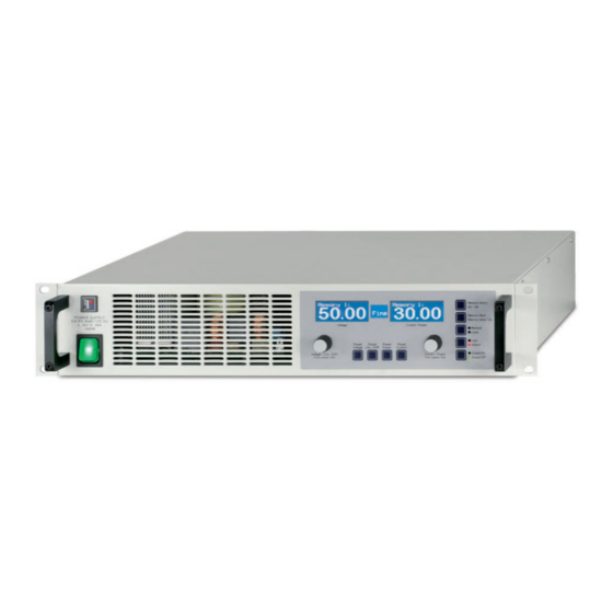
Elektro-Automatik PS 8065-10 2U Instruction Manual (52 pages)
Laboratory Power Supply
Brand:
Elektro-Automatik
| Category:
Power Supply
| Size: 3 MB
Table of Contents
Table of Contents
4
技术规格
5
控制面板和显示器
5
技术规格
6
产品描述
9
各面视图
9
供应清
10
一般信息
11
序言/安全警告
11
操作产品
11
与市电的连接
11
4U型号的市电连接
11
直流输入端
11
感测"端 (远程感测)
11
接口卡插槽
11
控制面板各按钮
12
Preset Voltage按钮
12
Preset Uvl / Ovp按钮
13
Preset Power按钮
13
Preset Current按钮
13
Memory Select M1-M5按钮
13
Memory Start / Memory Save >3S按钮
14
Local按钮
14
Lock / Unlock按钮
14
Output On / Output Off按钮
14
其它控制键
15
调节设定值
15
产品特性
15
用电源开关打开
15
用电源开关关闭
15
转至远程控制模式
15
过压报警
15
过温报警
15
调整电压、电流或功率
16
远程感测被激活
16
市电出现欠压或过压
16
连接不同类型的负载
16
产品设置
17
数字接口卡
18
模拟接口
18
一般信息
18
应用举例
19
模拟接口各引脚分布说明
20
其它应用
21
终端系统总线的功能
21
主-从模式下的串联
21
Irrtümer Und Änderungen Vorbehalten
22
共享总线模式下的并联
22
混合连接
23
其他
24
其它附件和选项功能
24
固件更新
24
Introduction
29
Technical Specifications
29
Control Panel and Display
29
Technical Specifications
30
Device Description
33
Views
33
Scope of Delivery
34
General
35
Prologue / Warning
35
Cooling
35
Maintenance / Repair
35
Installation
35
Visual Check
35
Mains Connection 2U Models
35
Mains Connection 4U Models
35
DC Output Terminal
35
Terminal „Sense" (Remote Sense)
35
Handling
36
The Display
36
Pushbuttons on the Control Panel
36
Pushbutton Preset Voltage
36
Pushbutton Preset UVL / OVP
37
Pushbutton Preset Power
37
Pushbutton Preset Current
37
Pushbutton Memory Select M1-M5
38
Pushbutton Memory Start / Memory Save >3S
38
Pushbutton Local
38
Pushbutton Lock / Unlock
38
Pushbutton Output on / Output off
38
Other Control Elements
39
Rotary Knobs
39
Adjusting Set Values
39
Device Characteristics
40
Switching on by Power Switch
40
Switching off by Power Switch
40
Switching to Remote Control
40
Overvoltage Alarms
40
Overtemperature Alarms
40
Voltage, Current and Power Regulation
40
Remote Sense Operation
41
Mains Undervoltage or Overvoltage
41
Connecting Different Types of Loads
41
Device Setup
41
Digital Interface Cards
42
Analogue Interface
43
General
43
Application Examples
43
Pin Specification
45
Other Applications
46
Functions of Terminal System Bus
46
2006, Elektro-Automatik Gmbh & Co. KG
46
Series Connection in Master-Slave Mode
46
Irrtümer Und Änderungen Vorbehalten
46
Parallel Connection (Share Bus)
47
Mixed Connections
48
Networking
48
Miscellaneous
49
Accessories and Options
49
Firmware Update
49
Advertisement
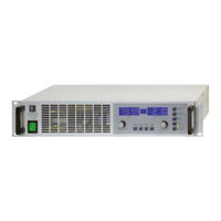
Elektro-Automatik PS 8065-10 2U Manual (48 pages)
Laboratory Power Supply
Brand:
Elektro-Automatik
| Category:
Power Supply
| Size: 2 MB
Table of Contents
Deutsch
4
Table of Contents
4
Bedien- und Anzeigeeinheit
5
Einleitung
5
Technische Daten
5
Gerätespezifische Daten
6
Gerätebeschreibung
9
Ansichten
9
Lieferumfang
10
Sichtprüfung
11
Anschlußklemme Fernfühlung
11
Anschluss DC-Ausgang
11
Netzanschluß 4HE-Modelle
11
Installation
11
Gerät Öffnen
11
Kühlung
11
Vorwort / Warnhinweis
11
Allgemeines zum Gerät
11
Netzanschluß 2HE-Modelle
11
Bedienung
12
Die Anzeige- und Bedieneinheit
12
Tasten am Bedienfeld
12
Weitere Bedienelemente
15
Sollwerte Einstellen
15
Überspannung
16
Spannungs-, Strom- und Leistungsregelung
16
Übertemperatur
16
Ausschalten mit dem Netzschalter
16
Umschalten auf Fernsteuerung (Remote)
16
Einschalten mit dem Netzschalter
16
Verhalten des Gerätes
16
Fernfühlungsbetrieb
17
Anschluß Verschiedener Lasttypen
17
Geräte-Setup
17
Netzüber-/Netzunterspannung
17
Allgemeines
18
Übersicht Sub-D-Buchse
18
Die Analogschnittstelle
18
Digitale Schnittstellenkarten
18
Pinspezifikation
19
Anwendungen
20
Weitere Anwendungen
21
Funktionen der Klemme System Bus
21
Reihenschaltung als Master-Slave
21
Parallelschaltung IM Share-Bus-Betrieb
22
Gemischte Verschaltungen
23
Vernetzung
23
Ersatzableitstrommessung nach DIN VDE 0701
24
Firmwareaktualisierung
24
Zubehör und Optionen
24
Sonstiges
24
English
26
Control Panel and Display
27
Introduction
27
Technical Specifications
27
Technical Specifications
28
Device Description
31
Views
31
Scope of Delivery
32
Cooling
33
DC Output Terminal
33
General
33
Installation
33
Mains Connection 2U Models
33
Mains Connection 4U Models
33
Opening the Device
33
Prologue / Warning
33
Terminal „Sense" (Remote Sense)
33
Visual Check
33
Handling
34
Pushbuttons on the Control Panel
34
The Display
34
Adjusting Set Values
37
Further Control Elements
37
Behaviour of the Device
38
Overtemperature Occurs
38
Overvoltage Occurs
38
Switching off by Power Switch
38
Switching on by Power Switch
38
Switching to Remote Control
38
Voltage, Current and Power Are Regulated
38
Connecting Different Types of Loads
39
Device Setup
39
Mains Undervoltage or Overvoltage Occurs
39
Remote Sense Is Active
39
Digital Interface Cards
40
General
40
Overview D-Sub Socket
40
The Analogue Interface
40
Pin Specifications
41
Example Applications
42
Functions of Terminal System Bus
43
Other Applications
43
Series Connection in Master-Slave Mode
43
Parallel Connection (Share Bus)
44
Mixed Connections
45
Networking
45
Accessories and Options
46
Firmware Update
46
Miscellaneous
46
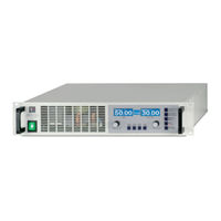
Elektro-Automatik PS 8065-10 2U Manual (40 pages)
Laboratory Power Supply Series, 640W-3000W, 32V-720V, 4A-120A
Brand:
Elektro-Automatik
| Category:
Power Supply
| Size: 2 MB
Table of Contents
Deutsch
4
Table of Contents
4
1 Einleitung
5
2 Technische Daten
5
Bedien- und Anzeigeeinheit
5
Gerätespezifische Daten
6
3 Gerätebeschreibung
7
Ansichten
7
Lieferumfang
8
4 Allgemeines zum Gerät
8
Vorwort / Warnhinweis
8
Kühlung
8
Gerät Öffnen
8
5 Installation
8
Sichtprüfung
8
Netzanschluss
8
Anschluss DC-Ausgang
8
Anschlußklemme Fernfühlung
8
Tasten am Bedienfeld
9
Weitere Bedienelemente
11
Sollwerte Einstellen
11
7 Verhalten bei
12
Einschalten mit dem Netzschalter
12
Ausschalten mit dem Netzschalter
12
Umschalten auf Fernsteuerung (Remote)
12
Überspannung
12
Übertemperatur
13
Spannungs-, Strom- und Leistungsregelung
13
Fernfühlungsbetrieb
13
Netzüber-/Netzunterspannung
13
Anschluß Verschiedener Lasttypen
13
8 Geräte-Setup
14
9 Digitale Schnittstellenkarten
14
10 Analoge Schnittstelle
14
Allgemeines
14
Anwendungen
15
11 Sonstiges
16
Ersatzableitstrommessung nach DIN VDE 0701
16
Funktionen der Klemme System Bus
17
Reihenschaltung als Master-Slave
17
Parallelschaltung IM Share-Bus-Betrieb
18
Networking
19
English
24
1 Introduction
25
2 Technical Specifications
25
Control Panel and Display
25
Technical Specifications
26
3 Device Description
27
Scope of Delivery
28
4 General
28
Prologue / Warning
28
Cooling
28
Opening the Device
28
5 Installation
28
Visual Check
28
Mains Connection
28
DC Output Terminal
28
Terminal „Sense" (Remote Sense)
28
Pushbuttons on the Control Panel
29
Further Control Elements 1
31
Adjusting Set Values 1
31
7 Behaviour of the Device When
32
Switching on by Power Switch 2
32
Switching off by Power Switch 2
32
Switching to Remote Control 2
32
Overvoltage Occurs 2
32
Overtemperature Occurs 2
32
Voltage, Current and Power Are Regulated
33
Remote Sense Is Active
33
Mains Undervoltage or Overvoltage Occurs
33
Connecting Different Types of Loads
33
8 Device Setup
34
9 Digital Interface Cards
34
10 Analogue Interface
34
General 4
34
Example Applications
35
11 Miscellaneous
36
Functions of Terminal System Bus 6
36
Series Connection in Master-Slave Mode 6
36
Parallel Connection in Share Bus Mode 6
36
Networking 7
37
Advertisement
Advertisement
Related Products
Elektro-Automatik PS 8065-10 DT
Elektro-Automatik PS 8065-05 DT
Elektro-Automatik PS 8065-05T
Elektro-Automatik PS 8065-10T
Elektro-Automatik PS 8032-20 2U
Elektro-Automatik PS 8080-40 DT
Elektro-Automatik PS 8080-60 DT
Elektro-Automatik PS 8032-20 DT
Elektro-Automatik PS 8040-60 2U
Elektro-Automatik PS 8032-10T
Elektro-Automatik Categories
Power Supply
UPS
Enclosure
Test Equipment
Computer Hardware
More Elektro-Automatik Manuals
Login
Sign In
OR
Sign in with Facebook
Sign in with Google
Upload manual
Upload from disk
Upload from URL