
Related Manuals for MRC SRI6PF


Summary of Contents for MRC SRI6PF
- Page 1 Installation - Operation Manual FLY INCUBATORS SRI6PF/20PF-2 3, Hagavish st. Israel 58817 Tel: 972 3 5595252, Fax: 972 3 5594529 mrc@mrclab.com MRC. 6.23...
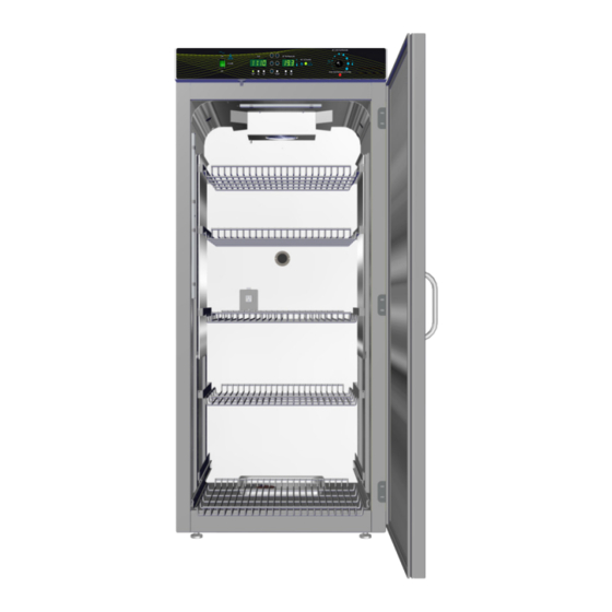
- Page 2 Pictured on Cover: SRI6PF-2 left, SRI20PF-2 right Warning: This product contains chemicals, including triglycidyl isocyanurate, known to the State of California to cause cancer as well as birth defects or other reproductive harm.
- Page 3 Refrigerated Incubator Peltier FLY 100 – 120 Voltage Models: SRI6PF and SRI20PF 220 – 240 Voltage Models: SRI6PF-2 and SRI20PF-2 Part Number (Manual): 4861674-1 P a g e...
-
Page 4: Table Of Contents
TABLE OF CONTENTS MODEL CERTIFICATIONS............................7 Electromechanical and Heating Safety ........................... 7 CE Compliant ................................... 7 UKCA Compliant ..................................7 ISO Certified Manufacturer ..............................8 INTRODUCTION ..............................9 Read this Manual ..................................9 Safety Considerations and Requirements ........................9 Contacting Assistance ................................ 10 Manufacturing Warranty .............................. - Page 5 Weight ...................................... 61 Dimensions ..................................... 61 Capacity ....................................61 Shelf Capacity by Weight ..............................62 Power ...................................... 62 Temperature ..................................63 PARTS AND CONSUMABLES ..........................65 P a g e...
- Page 6 TABLE OF CONTENTS P a g e...
-
Page 7: Model Certifications
MODEL CERTIFICATIONS Model Certification and Compliance Statements LECTROMECHANICAL AND EATING AFETY IEC 61010-1:2010, AMD1:2016 and 61010-2-010:2019 Safety Certified + USA, Canada, Europe Differences These unit models are certified by Intertek as compliant with the International Electrotechnical Commission’s 61010 safety standards for electrical and mechanical hazards as well as the heating of materials in laboratory devices. -
Page 8: Iso Certified Manufacturer
CERTIFICATIONS ISO Certified Manufacturer An ISO 9001 certified manufacturer P a g e... -
Page 9: Introduction
INTRODUCTION Thank you for purchasing an incubator. We know you have many choices in today’s competitive marketplace when it comes to constant temperature equipment. We appreciate you choosing ours. We stand behind our products and will be here if you need us EAD THIS ANUAL Failure to follow the guidelines and instructions in this user manual may create a protection impairment... -
Page 10: Contacting Assistance
ONTACTING SSISTANCE Phone hours for MRC Customer Support are 6 am – 4:30 pm Pacific Coast Time (west coast of the United States, UTC -8), Monday – Friday. Please have the following information ready when calling or emailing Customer Support: the model number, serial number, and part number (see page 17). -
Page 11: Temperature Reference Sensor Device
INTRODUCTION EMPERATURE EFERENCE ENSOR EVICE Must be purchased separately Temperature Temperature Calibrations Reference If you are not using a third-party service, a reference sensor device is required for calibrating your unit’s temperature display. See the Calibrating the Temperature Display procedure on page 53 for more information. •... - Page 12 INTRODUCTION 12 | P a g e...
-
Page 13: Receiving Your Unit
4. The unit should come with an Installation and Operation Manual. 5. Verify that the correct number of accessory items have been included. Model Shelves Static Shelf Brackets Sliding Shelf Brackets SRI6PF-2 SRI20PF-2 Model Leveling Feet Power Cord Humidification Kit... -
Page 14: Orientation Photos
RECEIVING RIENTATION HOTOS SRI20PFs Peltier Thermoelectric Chiller – Heater Housing Control Panel Access Port Door Gasket Day Phase Illumination LEDs Drain Port – TEC-H Housing Standard Shelf Bracket SRI20PF Chamber Power Outlet, NEMA 5-15R 100 – 120 Volt* Shelf Standard Rail Humidification Pan (behind the sliding shelf) Chamber Door... - Page 15 Day Phase Illumination LEDs Drain Port – TEC-H Housing SRI6PF Chamber Power Outlet, NEMA 5-15R 100 – 120 Volt* Humidification Pan Access Port Door Gasket Chamber Door *SRI6PF-2 Chamber Power Outlet, CEE7/3 220 – 240 Volt 15 | P a g e...
- Page 16 RECEIVING Data Plate Power Panel Chamber Access Port Second Fuse Holder (220V Incubators only) Power Panel Closeup Power Cord Inlet with Fuse Holder 16 | P a g e...
-
Page 17: Recording Data Plate Information
RECEIVING ECORDING LATE NFORMATION Record the unit model number, serial number, and part number below for future reference. Customer Support needs this information to provide accurate help during support calls and emails. The data plate is located on the left exterior wall of the incubator, toward the back and just •... - Page 18 RECEIVING 18 | P a g e...
-
Page 19: Installation
INSTALLATION NSTALLATION ROCEDURE HECKLIST Carry out the procedures and steps listed below to install the incubator in a new workspace location and prepare it for use. All procedures are found in the Installation section of this manual. Pre-Installation Check that the required ambient condition for the unit are met, page 20 ... -
Page 20: Required Ambient Conditions
Ambient Temperature Ranges: These units are built for use indoors under climate-controlled conditions of 15.0°C to 30.0°C (59.0°F to 86.0°F). SRI6PFs Ambient Impact on Cooling In workspace temperatures of 15.0°C to 27.0°C (59.0°F to 80.6°F) the SRI6PF incubators can • achieve an operational chamber temperature range of 15.0°C to 40.0°C. -
Page 21: Required Clearances
INSTALLATION EQUIRED LEARANCES These clearances are required to provide airflows for ventilation and cooling. 2” (5 1mm) 2” (51 mm) Power Cord Access Port 4” (102 mm) 4” (102 mm) 4” (102 mm) Door Swing SRI6PFs 30.5” (775 mm) SRI20PFs 30.5” (775 mm) 4 inches (102 mm) of clearance is required on the sides and back. -
Page 22: 100 - 120 Volt Power Source Requirements
OWER OURCE EQUIREMENTS Applies to: SRI6PF and SRI20PF When selecting a location for the unit, verify each of the following requirements is satisfied. Power Source: The power source must match the voltage and amperage requirements listed on the unit data plate. These units are intended for 100 – 120V 50/60 Hz applications at the following... -
Page 23: 220 - 240 Volt Power Source Requirements
OWER OURCE EQUIREMENTS Applies to: SRI6PF-2 and SRI20PF-2 When selecting a location for the unit, verify each of the following requirements is satisfied. Power Source: The power source for the unit must match the voltage and match or exceed the ampere requirements listed on the unit data plate. -
Page 24: Lifting And Handling
INSTALLATION IFTING AND ANDLING The unit is heavy. Use appropriate lifting devices that are sufficiently rated for these loads. Follow these guidelines when lifting the unit. Lift the unit only from its bottom surface. • Doors, handles, and knobs are not adequate for lifting or stabilization. •... -
Page 25: Install The Incubator
INSTALLATION NSTALL THE NCUBATOR Install the unit in a workspace location that meets the criteria discussed in the previous entries of the Installation chapter. EIONIZED AND ISTILLED ATER Do not use deionized water to clean the unit, even if DI water is readily available in your laboratory. The use of deionized water may corrode metal surfaces and voids the manufacturing •... -
Page 26: Install The Sri20Pf Side Air Ducts
Installation Insert the panel hooks, facing down, into the large notches in the shelf standard mounting rails. SRI6PF incubators do not use Side Air Ducts. Note: The air duct panels play an important role in maintaining even air distribution inside the SRI20PF incubation chamber. -
Page 27: Shelving Installation
INSTALLATION HELVING NSTALLATION Static Shelves Installation Remove all protective wrappings from shelves and shelving components prior to installation. Standard Shelf Bracket Installation Standard Bracket Installed Shelf hung from mounting bracket Insert the twin tabs on the bracket into slots in the shelf standard mounting rails located on the sides of the incubation chamber. - Page 28 INSTALLATION Shelving Installation Continued Sliding Shelf Installation SRI20PFs Note: SRI6PFs do not come with sliding shelf brackets. Sliding brackets for SRI6PFs must be purchased separately. 2. Slide the bracket down 1. Insert the sliding shelf mounting bracket tabs 3.2 Tighten the screws. 3.1.
-
Page 29: Access Port Stopper
INSTALLATION CCESS TOPPER Each incubator ships with a rubber stopper installed in the access port located in the back of the incubation chamber. The stopper should always be installed inside the chamber to obtain the • best temperature uniformity and prevent condensation from forming inside the port. - Page 30 INSTALLATION 30 | P a g e...
-
Page 31: Graphic Symbols
GRAPHIC SYMBOLS The unit is provided with multiple graphic symbols on its exterior. The symbols identify hazards and the functions of the adjustable components, as well as important notes in the user manual. Symbol Definition Consult the user manual. Consulter le manuel d'utilisation Temperature display Indique l'affichage de la température Over Temperature Limit system... - Page 32 SYMBOLS 32 | P a g e...
-
Page 33: Control Panel Overview
CONTROL PANEL OVERVIEW Control Panel Center Power Switch Power is supplied and the switch illuminates when in the ( I ) ON position. Time Display This display operates as a 24-hour clock (00:00 – 23:59), showing the current time. The display is also used to set the Daytime start time and the Nighttime start time for the day –... - Page 34 CONTROLS Enter Button Saves adjustments to the Current Time and the autocycle start times while in the Time Set Up menu. The Enter button can also be used to scroll forward through the menu without changing individual time settings. Mode Button Pushing the Mode button enters the Time Setup menu.
-
Page 35: Operation
OPERATION HEORY OF PERATION SRIPF fly incubators provide a variable temperature and illumination environment suitable for the cultivation and storage of fruit flies (Drosophila melanogaster). Heating and Cooling The incubator employs a solid-state thermoelectric cooling-and-heating (TEC-H) device, which operates using the Peltier effect to supply heating or cooling as needed. The Peltier effect: An electrical current between two touching but dissimilar conductor plates produces a heat flow from one plate to the other. - Page 36 OPERATION Manual and Autocycle Users can manually switch between Day and the Nighttime Modes by pressing and holding the MODE button. SRIPF incubators come from the factory set to Daytime Mode. The incubator is also provided with a Day – Night Autocycle. When launched, the cycle automatically switches between the two modes twice per day until manually terminated.
-
Page 37: Put The Incubator Into Operation
OPERATION UT THE NCUBATOR INTO PERATION Carry out the following steps and procedures to put the unit into operation after installing it in a new workspace environment Plug in the power cord. Attach the power cord that came with the unit to the power inlet receptacle on the back of the incubator. -
Page 38: Set Clock And Cycle Mode Start Times
OPERATION LOCK AND YCLE TART IMES This procedure performs the following functions: Sets the incubator clock time to local time. • Optional: Adjusts the Autocycle start times for the Day and Night modes. • The incubator comes from the factory set to US Pacific Time. The Autocycle Daytime start comes from the factory set to 08:00 (8 am), and the default Nighttime start is 20:00 (8 pm). - Page 39 OPERATION Set clock and cycle start times continued Save the Daytime start time and advance to the Nighttime start time. Push the Enter button This saves the flashing time value shown Push • on the display as the autocycle Day mode start time.
-
Page 40: Set The Night Mode Temperature
OPERATION ET THE IGHT EMPERATURE This procedure sets the temperature for the Nighttime mode used during both the autocycle and manual operations. Turn Off the Autocycle The Night and Day mode temperature setpoints cannot be changed while the Day – Night Autocycle is running. - Page 41 OPERATION Set the Night Mode Temperature Continued Wait for 5 seconds for the Setpoint to save. The display will stop flashing. The setpoint is now • saved in the controller. The display will revert to showing the current • chamber air temperature heating or cooling to match the new Night Mode setpoint.
-
Page 42: Set The Day Mode Temperature
OPERATION ET THE EMPERATURE This procedure sets the temperature for the Daytime mode used during both the autocycle and manual operations. Turn Off the Autocycle if On The Day and Night mode temperature setpoints cannot be changed while the Day – Night Autocycle is running. - Page 43 OPERATION Set the Day Mode Temperature Continued. Wait for 5 seconds for the Setpoint to save. The display will stop flashing. The setpoint is now • saved in the controller. The display will revert to showing the current • chamber air temperature heating or cooling to match the new Night Mode setpoint.
-
Page 44: Set The Over Temperature Limit
OPERATION Note: Test the OTL heating cutoff system at least once per year for functionality. Failure to set the OTL voids the manufacturing defect warranty if over temperature damage occurs. ET THE EMPERATURE IMIT The incubator temperature must be stable running at temperature in Day Mode for at least 1 hour prior to setting the OTL. - Page 45 OPERATION Set the Over Temperature Limit Continued Slowly turn the dial clockwise until the OTL Activated light turns off. Leave the OTL dial set just above the activation point. The Over Temperature Limit is now set close • to the current incubator air temperature Restore the Day Mode setpoint to the temperature of your study application.
-
Page 46: Loading Samples
OPERATION OADING AMPLES The manufacturer strongly recommends waiting at least 8 hours after putting the unit into operation before loading samples in the incubation chamber. This allows the unit to heat soak, protecting against temperature instability. Samples should be placed at least 1 inch (25 mm) away from the chamber walls. •... -
Page 47: Chamber Power Outlet
Each incubator comes with a 1-amp power outlet inside the chamber. Do not attach powered equipment that draws more than 1 amp. The SRI6PF and SRI20PF power outlet provides 100 – 120 volts. • The SRI6PF-2 and SRI20PF-2 power outlet provides 220 – 240 volts. -
Page 48: Condensation And The Dew Point
OPERATION ONDENSATION AND THE OINT Relative humidity inside the incubation chamber should never be allowed to exceed 80% at 25°C. Exceeding this threshold will likely result in condensation and leaks around the incubator and may cause corrosion damage if allowed to continue for any significant length of time. Condensation takes place whenever the humidity level in the incubation chamber reaches the dew point. -
Page 49: Door Alarm Setting
OPERATION Note: The Day – Night Autocycle must be off when turning the Door Alarm off or on. Note: Changing the Door Alarm setting accesses the Temperature Setpoint menu but does not adjust the temperature setpoint. LARM ETTING The incubator comes with a Door Alarm that sounds an audible alarm and causes the temperature display to blink on and off when the door has been open for longer than 60 seconds. - Page 50 OPERATION 50 | P a g e...
-
Page 51: User Maintenance
USER MAINTENANCE Warning: Disconnect this unit from its power supply prior to performing maintenance or services. Avertissement: Débranchez cet appareil de son alimentation électrique avant d'effectuer la maintenance ou les services. LEANING AND ISINFECTING If a hazardous material or substance has spilled in the unit chamber, immediately initiate your site Hazardous Material Spill Containment protocol. -
Page 52: Door Components
MAINTENANCE Disinfecting For maximum effectiveness, disinfection procedures are typically performed after cleaning. Keep the following points in mind when disinfecting the unit. Turn off and disconnect the unit to safeguard against electrical hazards. • Disinfect the unit chamber using commercially available disinfectants that are non-corrosive, •... -
Page 53: Calibrate The Temperature Display
MAINTENANCE ALIBRATE THE EMPERATURE DISPLAY Note: Performing a temperature display calibration requires a temperature reference device. Please see the Reference Sensor Device entry on page 11 for the device requirements. Temperature calibrations are performed to match the incubator temperature display to the actual air temperature inside the incubation chamber. - Page 54 MAINTENANCE 5. Autocycle Off The Autocycle must be turned off to conduct stable, accurate temperature • calibrations for the Day and Night Modes. 6. Set to Day Mode a. Place the incubator in Day Mode. This prepares the unit to calibrate the temperature display to the Day Mode temperature setpoint.
- Page 55 MAINTENANCE Day Mode Temperature Calibration Continued Place the display in its temperature calibration mode for Day Mode. a. Press and hold both the UP and DOWN arrow buttons simultaneously for approximately 5 seconds. b. Release the buttons when the temperature display shows the letters “C O”.
- Page 56 MAINTENANCE Day Mode Temperature Calibration Continued Reference Device Compare the reference device reading with the chamber temperature display again. If the reference device and the chamber temperature • display readings are the same or the difference falls within the range of your protocol, the incubator is calculated for Day Mode temperature.
- Page 57 MAINTENANCE Night Mode Temperature Calibration 1 Put the incubator into night mode. a. Press and hold the Mode button for 5 seconds to switch to modes. The Day Temp indicator light turns off and the Night • Temp light turns on. 2 Allow the incubator to achieve the Night Mode temperature and stabilize.
- Page 58 MAINTENANCE Night Mode Temperature Calibration Continued Place the display in its temperature calibration mode for Night Mode. a. Press and hold both the UP and DOWN temperature arrow buttons simultaneously for approximately 5 seconds. b. Release the buttons when the temperature display shows the letters “C O”.
- Page 59 MAINTENANCE Night Mode Temperature Calibration Continued Reference Device Compare the reference device reading with the chamber temperature display again. If the reference device and the chamber temperature • display readings are the same or the difference falls within the range of your protocol, the incubator is calculated for Night Mode temperature.
- Page 60 MAINTENANCE 60 | P a g e...
-
Page 61: Unit Specifications
UNIT SPECIFICATIONS The SRI6PF and SRI20PF incubators are 110 – 120 voltage units. The SRI6PF-2 and SRI20PF-2 are 220 – 240 voltage models. Please refer to the individual unit data plate for electrical specifications. Technical data specified applies to units with standard equipment at an ambient temperature of 25°C and a voltage fluctuation of ±10%. -
Page 62: Shelf Capacity By Weight
**Exceeding this weight limit risks damaging the shelf standard rails and the chamber liner. OWER 100 – 120 Volt Models Model AC Voltage Amperage Frequency SRI6PF 100 – 120 4.0 Amps 50/60 Hz SRI20PF 100 – 120 5.5 Amps 50/60 Hz 220 –... -
Page 63: Temperature
SPECIFICATIONS EMPERATURE Model Chamber Temp Range Uniformity Stability SRI6Ps 15° to 40°C @ 25°C Ambient* ±0.5° @ 20°C ±0.1°C @ 20°C SRI20Ps 15° to 40°C @ 25°C Ambient* ±0.5° @ 20°C ±0.1°C @ 20°C *Workspace temperatures can affect the lowest achievable operating temperature. SRI6PFs: Sustained ambient temperatures of 27.1°C (80.7°F) and hotter will impact the low- •... - Page 64 SPECIFICATIONS 64 | P a g e...
-
Page 65: Parts And Consumables
PARTS AND CONSUMABLES Description Part Number Description Part Number Power Cord, 125V SRI6PF, SRI20PF Access Port Stopper 15 Amp, 8ft 2in (2.5m), NEMA 5-15P 7750517 1800510 Power Cord 250V SRI6PF-2, SRI20PF-2 Feet, Adjustable Glide 10 Amp, 2.5m (8ft 2 inches), Euro CEE7/7...
Need help?
Do you have a question about the SRI6PF and is the answer not in the manual?
Questions and answers