
Subscribe to Our Youtube Channel
Related Manuals for MRC Compact


Summary of Contents for MRC Compact
- Page 1 Laser Beam Stabilisation System Compact User Manual Manual - Beam Stabilisation System Compact version 14 – 14-March-2022 page 1 of 28...
-
Page 2: Table Of Contents
9.1. Voltage offset inputs to move the target position on PSDs (“Adjust-in”)........24 9.2. Direct drive of Piezo actuators („Drive Actuator“)..............24 9.3. Option: External activation......................25 9.4. Intensity outputs at controller.......................25 9.5. Range outputs for monitoring applied Piezo voltages..............25 Manual - Beam Stabilisation System Compact version 14 – 14-March-2022 page 2 of 28... - Page 3 12.7. “Range” signals jump back and forth when switching the direction coding.......27 12.8. System steers the beam away from the centre................27 13. Safety............................28 14. Contact............................28 Subject to change without prior notice Manual - Beam Stabilisation System Compact version 14 – 14-March-2022 page 3 of 28...
-
Page 4: General
Figures 2, 3, and 4 (from left to right): Steering mirror with Piezo drive (version P2S30), detector with position and intensity display (horizontal orientation), detector (vertical orientation) Manual - Beam Stabilisation System Compact version 14 – 14-March-2022 page 4 of 28... -
Page 5: Specification
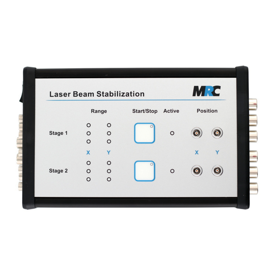
The system electronics (controller, amplifiers, power supplies) is fully integrated into a single compact housing. It is powered by a standard 12 V wall power supply. Figure 5: Keyboard and connectors on top panel Figure 6: Power input and output connectors... -
Page 6: Positioning Accuracy
Figure 8 shows the typical resolutions of the 4-quadrant detectors. The example demonstrates that a resolution of better than 100 nm on the detectors can be achieved with an appropriate choice of Manual - Beam Stabilisation System Compact version 14 – 14-March-2022... -
Page 7: Relation Between Measured Voltage And Actual Position
Here erfinv() is the inverse error function: D [µm] x [V ] x [µm] = ⋅erfinv ( I [V ] 2⋅ √ Manual - Beam Stabilisation System Compact version 14 – 14-March-2022 page 7 of 28... -
Page 8: Optical Components
10 x 10 mm 3 x 3 mm Ø = 3 mm 5 x 5 mm Element gap 30 µm 100 µm 45 µm 20 µm Manual - Beam Stabilisation System Compact version 14 – 14-March-2022 page 8 of 28... -
Page 9: Wide Intensity Detector - 4-Quadrant Diode With Wide Intensity Range
Therefore, we recommend performing a calibration if the target shall be moved along a defined path.The absolute accuracy at a stabilized position is not affected. Manual - Beam Stabilisation System Compact version 14 – 14-March-2022 page 9 of 28... -
Page 10: Vacuum Adaptions
The description of the adjustment and read-out of the P factor is given in section 5.8. The Directions switches enable a coding of the x and y directions of each control stage. They are connected with Det1 Manual - Beam Stabilisation System Compact version 14 – 14-March-2022... -
Page 11: Set-Up Of Optical Components
Figure 13 finally shows an arrangement where the 4-axes system is used as two 2-axes systems, • i.e. the two stages of the controller are used to separately stabilise two independent beam lines. Manual - Beam Stabilisation System Compact version 14 – 14-March-2022 page 11 of 28... - Page 12 A lens is components. Detector 2 must be placed in the placed in front of detector 2 which discriminates focal plane of the lens. for the angle. Manual - Beam Stabilisation System Compact version 14 – 14-March-2022 page 12 of 28...
-
Page 13: Connecting The Cables
If at least 3A are not available during the switch-on phase, the high-voltage modules do not reach their rated voltage and there is a risk of damage. Manual - Beam Stabilisation System Compact version 14 – 14-March-2022... -
Page 14: Intensity Adjustment
20. If you do not find a fitting adjustment, you can exchange the optical filters in front of the PSD sensors. Manual - Beam Stabilisation System Compact version 14 – 14-March-2022 page 14 of 28... -
Page 15: How To Replace The Optical Filters In The Detector Housing
The fine-adjustment should also be performed with inactivated control stages. The better the correlation of desired position and zero position of the Piezo actuators, the smaller the position shift once the closed- loop control is started. Manual - Beam Stabilisation System Compact version 14 – 14-March-2022 page 15 of 28... -
Page 16: Adjustment Of The Proportional Element (P Factor)
Note: The remote adjustment has to be driven with a low impedance voltage source (≤ 1 kOhm), whereas the read-out drives only high impedance terminations (≥ 1 MOhm). Manual - Beam Stabilisation System Compact version 14 – 14-March-2022 page 16 of 28... -
Page 17: Operation And Safety Features
It is LOW if the controller is active and one of the actuators is out of range. (If the controller is not active, the level is always HIGH.) Manual - Beam Stabilisation System Compact version 14 – 14-March-2022... -
Page 18: Bandwidth Limitation Switch
10 µs before until 50 µs after start of laser pulse Trigger end max. 1 ms after laser pulse end Trigger (digital) via serial interface Commands: “SetTriggerFreeze”, “ClearTriggerFreeze“ Manual - Beam Stabilisation System Compact version 14 – 14-March-2022 page 18 of 28... -
Page 19: Modes Of Operation
For an optimal function of the S&H circuit there are time restrictions for the trigger signal which should be met. Figure 18 illustrates the respective tolerances of the trigger signal. Manual - Beam Stabilisation System Compact version 14 – 14-March-2022... -
Page 20: Performance
“Automatic control” and “Operation with external trigger”. Without the S&H circuit it would have started from the upper position and would have produced a spike. Manual - Beam Stabilisation System Compact version 14 – 14-March-2022 page 20 of 28... - Page 21 Figure 21: Pulse trains without stabilisation Figure 22: Pulse trains with automatic control Manual - Beam Stabilisation System Compact version 14 – 14-March-2022 page 21 of 28...
- Page 22 Active LED on the front panel of the beam stabilisation system is directly connected to this time interval, it can happen that you will not recognise the shining of the LED due to the short time. Manual - Beam Stabilisation System Compact version 14 – 14-March-2022...
-
Page 23: Option: Serial Interface (Usb, Rs-232 Or Ethernet)
9. Additional inputs and outputs (Options) Beside the inputs for the detectors and the outputs to the actuators the basic configuration of the Compact beam stabilisation provides the following outputs: Position signals x and y of each detector (analog voltage signal -5 to +5 V) •... -
Page 24: Voltage Offset Inputs To Move The Target Position On Psds ("Adjust-In")
The voltage range of the Piezo actuators is specified as - 45 V to + 180 V. • We have specified the voltages for the valid range of the green Range LEDs on the control box • Manual - Beam Stabilisation System Compact version 14 – 14-March-2022 page 24 of 28... -
Page 25: Option: External Activation
10. Drawings Drawings of all main components can be found in the respective data sheets. On request, we are pleased to send you the corresponding STEP files. Manual - Beam Stabilisation System Compact version 14 – 14-March-2022 page 25 of 28... -
Page 26: Cables
11. Cables 11.1. Standard cables The standard delivery of a Compact laser beam stabilisation system includes all required cables to set up the system and to read out the positions. These are: Cable set for a 4-axes system quantity length (included in standard delivery) Detector →... -
Page 27: The Steering Mirrors Make Exceptional Noise
Adjust-in in the software. In this case, delete the corresponding values or switch to “external” in the software. Manual - Beam Stabilisation System Compact version 14 – 14-March-2022... -
Page 28: Safety
Figure 26: Labels on the controller electronics (left), the detectors (middle) and the actuators (right) 14. Contact MRC Systems GmbH Phone: +49 (0)6221/13803-00 Hans-Bunte-Strasse 10 Fax: +49 (0)6221/13803-01 D-69123 Heidelberg Website: www.mrc-systems.de Germany E-mail: info@mrc-systems.de Manual - Beam Stabilisation System Compact version 14 – 14-March-2022 page 28 of 28...
Need help?
Do you have a question about the Compact and is the answer not in the manual?
Questions and answers