
Related Manuals for MRC INE-112N-GC


Summary of Contents for MRC INE-112N-GC
- Page 1 User Manual INE-112N-GC Gas Chromatograph PLEASE READ THIS MANUAL CAREFULLY BEFORE OPERATION Hagavish st. Israel 58817 Tel: 972 3 5595252, Fax: 972 3 5594529 mrc@mrclab.com MRC.4.22...
- Page 2 This manual only applies to Model Gas Chromatograph, excluding large diameter INE-112N-GC capillary direct sampler, capillary split sampler, six-way plane switching valve, reformer, and other accessories. If you use these accessories, the corresponding manual will be attached in the package.
-
Page 3: Table Of Contents
Table of Contents 3.5 Installation of Packed Column ....... 12 1 Principles, Applications and Features ....1 3.6 Installation of Liner and Spacer of Split 1.1 Principles ............1 Sampler ..............19 1.2 Applications .............1 3.7 Installation of Capillary Column System ..21 1.3 Features ............2 4 Appearance and Structure of the System ... - Page 4 6.2 Sampler Interface ..........36 6.3 Column Oven Interface .........38 6.4 Detector Interface .........40 6.5 File Management Interface (For Automatic Model) ..............43 6.6 System Configuration Interface .....47 6.7 Online Configuration Interface ......49 7 Operation Examples ..........51 7.1 FID Detector ..........51 8 Maintenance and Troubleshooting .....56 8.1 Maintenance of the Instrument ....56 8.2 Cleaning of the Instrument ......57 9 Warranty..............71...
-
Page 5: Principles, Applications And Features
1.2 Applications The instrument has a wide range of applications and is suitable for trace detection of environmental protection, air, MRC Instrument... -
Page 6: Features
High-precision temperature control system, high control accuracy (better than ±0.05℃), the oven has a nine-phase programmed temperature; Manual flow/pressure adjustment of the gas path, the screen displays the flow/pressure value The gas path has air leak and air shortage alarm functions; System self-checking and fault identification functions; MRC Instrument... -
Page 7: Technical Indicators And Specifications
±0.1℃(measured at 200℃) Programmed nine-phase programmed temperature temperature Rate setting 0.1℃~40℃/min (increment: 1℃), measured at 200℃ Constant temp time 0~999min (increment: 1℃) Sampler, Flame Ionization Detector (FID) Indicators Temperature range 15℃~399℃ above room temperature (increment: 1℃) MRC Instrument... -
Page 8: Specifications
Chromatograph Series User Manual Temperature accuracy better than ±0.1℃(measured at 200℃) Flame Ionization Detector Detection limit INE-112N-GC (Normal D≤3×10 hexadecane in isooctane) 399℃ Max. limit temp Baseline noise ≤5×10 Baseline drift ≤1×10 A/30min 2.2 Specifications INE-112N-GC Dimensions 568mm×560mm×490mm Weight 40Kg Power supply voltage AC220V±22V, 50Hz±1Hz... -
Page 9: Optional Accessories
Accessories and spare parts (see Packing List) 1 set The following accessories of Model INE-112N-GC gas chromatograph are optional, and can be ordered with the basic instrument (if needed). They can also be ordered at any time after the instrument has been operated. -
Page 10: Installation Instructions
The instrument should be placed on a solid stable laboratory bench which complies with the environmental requirements. The ambience shall maintain clean, free of severe dust pollution. To ensure that the instrument works normally, the working environment shall meet following criteria: MRC Instrument... -
Page 11: Unpacking Check
Open the package (please save the outer packing box in case you need to move it), and count the host and spare parts according to the accessory spare parts list. If there is any error, please contact your local sales agent or contact our company directly. MRC Instrument... -
Page 12: Preparation And Treatment Of Gas Source
3.3 Preparation and Treatment of Gas Source 3.3.1 Gas Source The FID detector of INE-112N-GC needs three types of gas, i.e. carrier gas (generally, nitrogen), hydrogen and air. The purity of the nitrogen must not be lower than 99.99%, and that of the hydrogen not be lower than 99.9%. -
Page 13: External Gas Flow Connection
3.4.1 Connect the pipeline to the connector INE-112N-GC gas chromatograph gas pipeline mainly consists of 3×0.5 polyethylene duct (Annex 28 #) or 2×0.5 stainless steel duct. Nuts are M8×1, 3.2 (Attachment 24 #) or M8×1, 2.1 (Attachment 7 #). The connection diagram of these two kinds of conduits and joints is shown in Figure 3.4.1. - Page 14 Two pieces of airproof coils (accessory 22#) φ3×0.5 polyethylene pipe (accessory 28#) Airproof gasket (φ2×0.5×20 stainless steel pipe) (accessory 23#) Joint φ2×0.5 stainless steel pipe Nut (M8×1, φ2.1) (accessory 7#) Figure 3.4.1 The connection of the external gas flow joint MRC Instrument...
- Page 15 ‧ Turn on the high pressure valve of the steel cylinder (before doing so, the low adjustment lever must be in a relaxed state), slowly turn the low pressure adjustment lever until the low pressure gauge indicates 3kg/cm2. MRC Instrument...
-
Page 16: Installation Of Packed Column
3.5.1 Install φ3mm and φ4mm metal columns to the inlet of packed column Use Figure 3.5.1 as the installation instructions: Mount the nut (SN#: 6), graphite airproof gasket (SN#: 4) and packed column transition joint (SN#: 1) into the packed column in sequence. MRC Instrument... - Page 17 (Note: the lower end of the gasification tube must be inserted into the column head). Keep this position, first tighten the nut (M12×1, φ6.2) with the injector outlet connector by hand, and then tighten it with an M12 wrench and seal it. MRC Instrument...
- Page 18 (accessory 16#) (accessory 16#) φ φ M12×1, M12×1, (accessory 24#) (accessory 24#) φ φ Graphite gasket (accessory 17#) (accessory 19#) φ φ Metallic column (outside diameter) (outside diameter) φ φ M8×1, M8×1, (accessory 27#) (accessory 28#) Figure 3.5.1 MRC Instrument...
- Page 19 Hold this position. First, tighten the nut to the sampler outlet joint with hand. Then, tighten it with wrench M12 and seal it. Warn: During the installation of glass column, if the nut is over-tightened, the column will be broken. Please be careful with the operation. MRC Instrument...
- Page 20 Specification φ5 metallic φ6 metallic φ5.7 glass Packed column column column column φ5 φ6 φ6 Graphite airproof gasket (accessory 18#) (accessory 16#) (accessory 16#) M12×1, φ5.2 M12×1, φ6.2 M12×1, φ6.2 (accessory 25#) (accessory 24#) (accessory 24#) Figure 3.5.2 MRC Instrument...
- Page 21 Hold this position. First, tighten the nut (M12×1, φ6.2) to the sampler outlet joint with hand. Then, tighten it with wrench M12 and seal it. Figure 3.5.3 For gas sampling, install column to FID detector in the same manner as above. MRC Instrument...
- Page 22 After the column is installed, all joint nuts should be tested for leaks at room temperature and the operating temperature of the oven, sampler, and detector. If necessary, tighten with a wrench to prevent air leakage. Figure 3.5.4 MRC Instrument...
-
Page 23: Installation Of Liner And Spacer Of Split Sampler
After using for a period of time, remove the adsorption tube (filter) which is installed in the middle of the oven, refer to Figure 3.6. Replace the new MRC Instrument... - Page 24 Chromatograph Series User Manual adsorbent. Fill the tube with a little glass wool at both ends. Figure 3.6 MRC Instrument...
-
Page 25: Installation Of Capillary Column System
Finally, hang the capillary column (with the frame) on the rack. Use the knurled screw to adjust the height of rack Rack assembly Capillary Two φ3 screws to fix the rack assembly Figure 3.7.1 Schematic Diagram of Capillary Rack MRC Instrument... - Page 26 Chromatograph Series User Manual The capillary analysis system of INE-112N-GC series can use a variety of capillary columns, such as a glass capillary column and a flexible quartz capillary column (fused silica capillary column). The external diameter of optional glass capillary column is 0.9mm ~ 1mm;...
- Page 27 As shown in Figure 3.7.2, hold the position of capillary column which extends from the nut M5 for 27mm. First, hand-tighten the nut and the joint, then use an 8-inch wrench to tighten the nut. Figure 3.7.2 MRC Instrument...
- Page 28 Place the M5, φ1.6 nut and strip graphite gasket respectively onto the capillary column. As shown in Figure 3.7.3, push the capillary to the bottom, hand-tighten the nut and the joint, then tighten and seal the M5 nut with the 8# wrench. Figure 3.7.3 MRC Instrument...
-
Page 29: Appearance And Structure Of The System
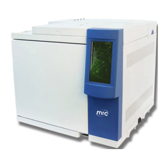
User Manual 4 Appearance and Structure of the System 4.1 Appearance of the Instrument INE-112N-GC gas chromatograph consists of the detector, sampler, column oven, flow control section means, temperature control and detector circuit parts and other components. The middle part of the basic type is the oven, the upper right part... -
Page 30: Layout
Chromatograph Series User Manual 4.2 Layout Figure 4.2.a INE-112N-GC Front View/Left View/Right View/Top View MRC Instrument... - Page 31 Chromatograph Series User Manual Figure 4.2.b INE-112N-GC Back View MRC Instrument...
-
Page 32: Structural System
This chapter mainly introduces the installation and operating instructions of the split injector. The basic accessories of the INE-112N-GC instrument contain the corresponding liners and connectors for the capillary split injector. If users need to order other samplers for capillary columns, the instructions are attached separately. - Page 33 (6 pieces in parallel). Fuses are provided in the accessories. 4.3.3 Detector System INE-112N-GC detector configuration: hydrogen flame ionization detector (FID), thermal conductivity detector (TCD). The user can choose to mount either one or both, FID and TCD. The FID detector of INE-112N-GC is installed on the MRC Instrument...
- Page 34 FID detector on the top of the column box, and it is connected and sealed with a nut and a graphite gasket. Hydrogen and air are introduced from the joint of the gas control system above the host by stainless steel pipes. MRC Instrument...
-
Page 35: Operations
When the self-test is finished, the system will show a window to select whether to perform auto ignition. Click [YES] and the system enters the main interface and turn on the auto ignition system. Click [NO] to enter the main interface and turn off the auto-ignition system, and the user can manually execute ignition. MRC Instrument... -
Page 36: Keypad Operations
Chromatograph Series User Manual 5.2 Keypad Operations The keypad and status area of the model series can be switched, as shown in Figure 5.2. Figure 5.2 Keypad/Status MRC Instrument... -
Page 37: Basic Operations
Refer to area [A] in Figure 6.1. The upper part of the interface, the area marked in blue and gray is the temperature profile display area. This area in the programmed temperature state, you can see the programmed temperature curve and where the current temperature is. Figure 6.1 Monitor Interface MRC Instrument... - Page 38 Refer to area [D] in Figure 6.1. This area is mainly for users to view the basic information, including the real-time data of oven temperature, pre-column pressure, the signal value and the total flow. Figure 6.1.5 Parameter View Window MRC Instrument...
- Page 39 After the equipment is turned on, it’ll show the yellow "NOT READY" status. When it detects the temperature of each module, the data of gas channel will reach the set value range (for the FID detector, the ignition needs be successful), it will display the green "READY" state, indicating that instrument is ready for testing. MRC Instrument...
-
Page 40: Sampler Interface
(the minimum input figure is 0.1 degree). Click [ENTER] to finish. For the heating switch, click [Heating On] to start heating, and click [Heating off] to stop heating. The upper black box shows the actual temperature and switch status of the Figure 6.2 Sampler Interface MRC Instrument... - Page 41 Operation method: directly use the touch pen to click the drop-down button, there are several types to choose from in the drop-down menu, and the current type will be automatically displayed, and the user can select from the available types. MRC Instrument...
-
Page 42: Column Oven Interface
The setting value will be displayed automatically. Use the keypad to input the temperature (the minimum input figure is 0.1 degree). Click [ENTER] to finish. For the heating switch, click [Heating On] to start heating, and click [Heating off] to stop heating. Figure 6.3 Column Oven Interface MRC Instrument... - Page 43 See area [C] in Figure 6.3. For oven temperature control method, there are two options, one is constant temperature control method and the other is the programmed temperature control. 6.3.4 Programmed Temp Control Setting See area [D] in Figure 6.3. MRC Instrument...
-
Page 44: Detector Interface
Note: After the data of each stage is set, the user must click the button in D area to save the data. 6.4 Detector Interface MRC Instrument... - Page 45 User Manual In other interfaces, click [Detector] in the menu bar to enter this functional module. INE-112N-GC provides logarithmic FID detector (Figure 6.4). 6.4.1 Temp Control Area Refer to area [A] in Figure 6.4. For the Temp Control function, it includes temperature setting, display the real testing value and [Heating On]/ [Heating Off].
- Page 46 As shown in the [D] area of Figure 6.4. Detector flow setting control area, it can set the flow of hydrogen, air, and makeup gas. When the user adjusts the corresponding flow knob, the above flow value will change. MRC Instrument...
- Page 47 The detector’s ignition status switch is used when the detector needs to be ignited or if the flame is re-ignited after flameout. Click the button, the interface will be prompted. To confirm the ignition, click [YES]; or to cancel, click [NO]. Whether the ignition is successful, a prompt box will show. Figure 6.4.7 Flow status bar MRC Instrument...
-
Page 48: File Management Interface (For Automatic Model)
When the user does not store the file, the file name is always displayed as "Current", and shows the initialization data of the system. When the user changes the instrument information, and save Figure 6.5 File Management Interface MRC Instrument... - Page 49 After entering the file name, click [OK] to display the file sequence window as shown in Figure 6.5.2-B. There are 20 storage locations to choose from. Select the storage location as needed in the "File Sequence", as shown in Figure 6.5.2-C. Click [YES] to save the current MRC Instrument...
- Page 50 Click [Load] to recall the previously saved file, as shown in Figure 6.5.2-B. Select the file to be loaded, confirm it and the file will be loaded to “file 1” position, and all current information will be updated. The contents of the original file remain unchanged. Figure 6.5.2-A Input File Name Figure 6.5.2-B File Sequence Figure 6.5.2-C Prompt Message MRC Instrument...
-
Page 51: System Configuration Interface
In other interface, click [System Configuration] to enter this function module. Refer to Figure 6.6. 6.6.1 Information Refer to area [A] in Figure 6.6. The basic information of the instrument is set at the factory, and the user MRC Instrument Figure 6.6 System Configuration Interface... - Page 52 You can use this button to view the relationship between several groups of injections and detections. As in the [D] area of Figure 6.6, press [Connection Setting] button to set the connection between the sampler and the detector when the button is activated. MRC Instrument...
-
Page 53: Online Configuration Interface
As shown in the [B] area of Figure 6.7. It is used to set up the networking configuration of the GC. The user can select static or dynamic IP address. When selecting a static IP address, you can set a specific static IP address Figure 6.7 Online configuration interface MRC Instrument... - Page 54 See area [D] in Figure 6.7. If the contents of the online configuration are modified, click the [Save Current Configuration] button, the system will save the updated information. If you fail to not click, the previous changes will not be saved. MRC Instrument...
-
Page 55: Operation Examples
Turn on the carrier gas source and rotate the pressure regulator until the carrier gas flow reaches the appropriate value (according to the separation conditions). Turn on the power, and follow the above instructions in Chapter II to set the temperature of oven, detector and MRC Instrument... - Page 56 Note: To make it simple, the back-end equipment only uses a recorder as an example. If you are using a chromatographic data processor or a chromatographic workstation, refer to the specific operating instructions, including the operation of necessary signal attenuation. MRC Instrument...
- Page 57 In order to facilitate ignition, it is recommended to adjust the hydrogen flow rate faster first, and then to ignite. After ignition, slowly adjust the hydrogen flow back to the required flow value for analysis. Before the instrument is shut down, the hydrogen (fire) should be closed off, cooling, and then close the carrier gas. MRC Instrument...
- Page 58 FID or screwed into the M12 × 1 nut with a φ6 graphite gasket FID Detector inlet, tighten and seal with wrench. MRC Instrument...
- Page 59 Chromatograph Series User Manual MRC Instrument...
-
Page 60: Maintenance And Troubleshooting
Generally, the column temperature is lower than the recommended temperature range in the stationary phase. When the high sensitivity operation is going on, the column temperature should be set lower. When the carrier gas is transmitted into INE-112N-GC, the pressure should be set at 343000Pa (equivalent to MRC Instrument... -
Page 61: Cleaning Of The Instrument
The method to remove the upper part of the FID cover (collector section): unscrew the two central knurled screws from the FID cover with hand, hold of the collector terminal, and pull upward with force the upper part MRC Instrument... - Page 62 Then blow a large flow of carrier gas into the tube (mainly to blow out the cotton fiber and dry the solvent). Then assemble the gasification tube and the chromatography column, place in a new airproof silica gel gasket and turn the heat dissipation gasket tight. MRC Instrument...
- Page 63 Turn the chromatography column tight. There is no fire (FID). Ignite the fire. FID polarization voltage is not connected Connect the polarization voltage or or is in poor contact. make sure that the polarization voltage is in good contact. MRC Instrument...
- Page 64 (leftover of sample or silica gel). Clean the sampler’s tube with the The temperature of the chromatography solvent. column oven is too low. Increase the temperature of the The injection technique is chromatography column. underdeveloped. Improve the injection technique and MRC Instrument...
- Page 65 Wrong choice of stationary liquid or Replace the chromatography column or support. the aging column. The carrier gas flow is too fast. Select proper column. Injection technique is too poor. Slow down the carrier gas flow. Improve the injection technology. MRC Instrument...
- Page 66 Eliminate the external electric field The hydrogen flow and air flow are not which can affect the normal work of properly set (FID). the instrument Readjust the hydrogen flow and air flow, especially the air flow MRC Instrument...
- Page 67 Choose the proper stationary liquid and properly selected (FID). process the column with thoroughly The amplifier is not stabilized. aging treatment. The column temperature should not be raised to the operating limit of the stationary liquid (especially the high sensitivity MRC Instrument...
- Page 68 The sample is decomposed. establish the appropriate operating height The sample is contaminated. conditions. The sample reacts with the stationary Exhaust the air in the sampler liquid, the support or the absorbent. Reduce the sampler’s temperature (the MRC Instrument...
- Page 69 The flow rate of the carrier gas is too Set a suitable carrier gas flow rate. appears (FID). high. Clean the flame nozzle (or remove the The flame nozzle is contaminated (or blockage from the flame nozzle). MRC Instrument...
- Page 70 Adjust the flow rate of hydrogen and air. 16. Short burrs at Water condenses in the hydrogen tube Eliminate the water from the tubing even intervals (the water usually comes from the and replace or activate the desiccant in hydrogen source). the hydrogen filter. MRC Instrument...
- Page 71 The high resistance is contaminated. Identify the contaminated high The sampler is contaminated resistance and clean it. The hydrogen flow rate is too high or too Clean the sampling tube of the sampler low (FID). and remove the residue of silica gel. MRC Instrument...
- Page 72 The pressure of the gas flow is too low. Replace the carrier gas cylinder. Air and hydrogen are not adjusted well Regulate the hydrogen and air flow. (FID). 19. One-way baseline There is a significant increase or Stabilize the detector temperature. If MRC Instrument...
- Page 73 21. Irregular baseline The leak in the column is too much. Select an appropriate chromatography change appears The operating conditions are not column. The operating column when the appropriate. temperature should be far lower than MRC Instrument...
- Page 74 There are ghost peaks when the silica the stationary liquid gel is heated. Set the suitable operating conditions Replace the chromatography column. Pre-heat the silica gel at the temperature of 200°C for 16 hours before use. MRC Instrument...
-
Page 75: Warranty
Within 12 months after the user purchased the instrument, if it doesn't work properly without any physical damages, the factory is responsible for repair free of charge (not including the consumable parts; source lamp and cuvette not covered by the warranty). MRC Instrument...
Need help?
Do you have a question about the INE-112N-GC and is the answer not in the manual?
Questions and answers