Table of Contents
Advertisement
Quick Links
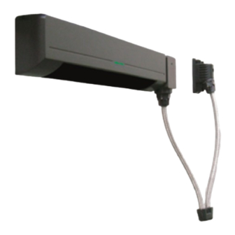
ELITE T
Swing Door
Door Mounting Sensor
5924384 DEC 2022
Manufacturer's statement
Read this operation manual carefully before use to ensure proper operation of this product.
Failure to read this operation manual may cause improper operation and may result in serious injury or death of a person. The meanings of the symbols are as follows.
WARNING
Failure to follow the instructions provided with this indication and improper handling may cause death or serious injury.
CAUTION
Failure to follow the instructions provided with this indication and improper handling may cause injury and/or property damage.
NOTE
Special attention is required to the section of this symbol.
1. Set door speeds and verify proper operation of door manufacturer's equipment prior to applying power to the sensor system.
2. Do not install the sensor where it might be directly sprayed with rainwater.
3. Verify proper wiring prior to applying power to the sensor system to prevent damage to equipment.
4. When setting the sensor's area pattern, make sure there is no traffic around the installation site.
5. Do not attempt to rebuild or repair sensor heads or control unit. Contact an address in this manual for replacement products.
6. Only use the sensor as specified in the supplied instructions.
7. Walk test the installation to verify operation is in compliance with all local laws, codes and standards of your country.
8. Upon completion of installation and adjustments, instruct the owner/operator on proper operation of the door and sensor system. Identify any switches/breakers that will place
the door out of service when unsafe or improper operation is identified.
Specifications
Model
Cover color type
Mounting height
Detection area
Detection method
Detection angle adjustments
Operation indicator *
Insure proper setting of mode switch #8 indicating approach side or swing side sensor.
NOTE
The specifications herein are subject to change without prior notice due to improvements.
* : LED will be turned off approx. 500 ms when the sensor test output signal works well.
Dimensions and part names
10 3/4"(275)
: OA-603 T
: Black
: 6'7" to 8'2" (2.0 m to 2.5 m)
: See the chart in "Adjustments"
: Active infrared reflection
(Presence detection type)
: Threshold area ±5˚(inside & outside)
: Swing area ±5˚(inside & outside)
: Green : Stand-by
Red blinking : Threshold area detection active
Red : Swing area detection active
Yellow blinking : Learning
Operation indicator
Current draw
Response time
Operating temperature
Weight
Accessories
(1)
(9)
(5)
(1)
Connector
(2)
Sensitivity potentiometer
(3)
Mode setting switches
(Area depth adjustment, Auto learning timer,
Frequency, Rain mode, Snow mode)
[inch(mm)]
(4)
Area width switch
1-1
: 120 mA Max
: < 0.3 s
: -4˚F to +131˚F (-20˚C to +55˚C)
: 8.2 oz (230 g)
: 1 Sensor cable 7"(0.2 m)
9 Mounting screws
1 Operation manual
3 Mounting template
9 3/4 " (248)
(3)
(2)
(4)
OPERATION INDICATOR
OA-603 T
(6)
(10)
(7)
(5)
Threshold area angle screw
(6)
Threshold area angle gauge
(7)
Swing area angle gauge
(8)
Swing area angle screw
(9)
Mounting holes
(10)
Operation indicator
(1)
(9)
(8)
Advertisement
Table of Contents


Need help?
Do you have a question about the ELITE T and is the answer not in the manual?
Questions and answers