
Related Manuals for Ruijie Reyee RG-NBS6002


Summary of Contents for Ruijie Reyee RG-NBS6002
- Page 1 Ruijie Reyee RG-NBS6002 Switch Hardware Installation and Reference Guide Document Version: V1.0 Date: 2023.02.09 Copyright © 2023 Ruijie Networks...
- Page 2 All rights are reserved in this document and this statement. Any reproduction, excerption, backup, modification, transmission, translation or commercial use of this document or any portion of this document, in any form or by any means, without the prior written consent of Ruijie Networks is prohibited.
- Page 3 Technical support and servicing engineers Network administrators Technical Support The official website of Ruijie Reyee: https://www.ruijienetworks.com/products/reyee Conventions 1. Signs This document also uses signs to indicate some important points during the operation. The meanings of these signs are as follows: Caution An alert that calls attention to safety instruction that if not understood or followed can result in personal injury.
-
Page 4: Product Overview
Product Overview Product Overview RG-NBS6002 switch is 1U swappable box-type network switch independently developed by Ruijie Networks. It provides two line card slots for four types of line cards and two power supply module slots for 1+1 power redundancy. The following table describes components of an RG-NBS6002 switch. -
Page 5: Product Appearance
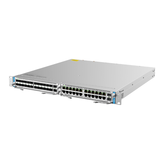
Mounting bracket Yellow/green ground cable Warranty Card User Manual Product management software of Ruijie Networks Instruction ● The preceding table lists items delivered in normal cases. The actually delivered items may vary with the contract. Carefully check your goods against the package contents or contract. Contact the seller if you have any questions or find any errors. - Page 6 Hardware Installation and Reference Guide Product Overview Rear View 1.1.3 Ports - Front Panel Figure 1-2 shows the front panel of an RG-NBS6002 switch. For the detailed meanings of numbers 1 to 7, see the following table. Figure 1-2 Front Panel of an RG-NBS6002 Series Switch (Service Module Combination of M6000- 16GT8SFP2XS and M6000-16SFP8GT2XS)
- Page 7 Hardware Installation and Reference Guide Product Overview Item Description Line card status indicator. The statuses are as follows: ● Solid green: The service module works properly. Line card status ● Blinking green: The service module is starting up. indicator ● Blinking yellow: Hot swapping or configuration conflict occurs.
- Page 8 Hardware Installation and Reference Guide Product Overview Figure 1-3 Rear Panel of an RG-NBS6002 Switch Item Description Grounding post Used to fasten the ground cable. MGMT port 10/100/1000Base-T adaptive Ethernet port. The port uses an RJ-45 connector. The management port is used for configuration and software upgrade.
-
Page 9: Technical Specifications
Hardware Installation and Reference Guide Product Overview Off: The system is not powered on. Note ● Reset button: When you press and hold the reset button for less than 2 seconds, all modules are reset. When you press and hold the reset button for more than 5 seconds, all modules are reset, the initial password is restored, the supervisor module is restored to factory settings, and the configuration backup file is saved. - Page 10 Hardware Installation and Reference Guide Product Overview Operating 0° C to 50° C (32° F to 122° F) Temperature Storage –40° C to 70° C (-40° F to 158° F) Temperature Operating 10% to 90% RH (non-condensing) Humidity MTBF > 200,000 hours Noise In an ambient temperature of 25°...
-
Page 11: Power Supply Appearance
Hardware Installation and Reference Guide Product Overview 1.2.1 Power Supply Appearance Figure 1-4 Appearance of an RG-PA150I-FS Power Supply Module RG-PA150I-FS is an AC power module with AC power input and provide s 12 V voltage to the entire RG-NBS6002 system. The front panel of the power supply provides a three-pin power socket, which is connected with a standard 10 A power cord. -
Page 12: Service Module
Hardware Installation and Reference Guide Product Overview Note ● When connecting a power cord, push up on the cable-retention clip that secures the input power cord to the power supply. ● Connect the power cords to a grounded output socket. ●... - Page 13 Hardware Installation and Reference Guide Product Overview 2. Front Panel Figure 1-6 Front Panel of M6000-24GT2XS Item Description Line card status indicator. The statuses are as follows: ● Solid green: The service module works properly. Line card status ● Blinking green: The service module is starting up. indicator ●...
- Page 14 24 10/100/1000BASE-T RJ-45 copper ports and two SFP+ ports Supported For details, see Transceiver Transceiver Modules. Copper cables are not supported. Modules and Supported models may be updated anytime. For details, consult Ruijie Networks Co., Ltd. Cable Types Indicator Status and Link/ACT indicators Hot Swapping Unsupported Power <...
- Page 15 Hardware Installation and Reference Guide Product Overview 1.3.3 M6000-24SFP2XS Service Module 1. Product Appearance Figure 1-7 Appearance of M6000-24SFP2XS 2. Front Panel Figure 1-8 Front Panel of M6000-24SFP2XS Item Description Line card status indicator. The statuses are as follows: ● Solid green: The service module works properly. Line card status ●...
- Page 16 24 SFP ports and two SFP+ ports Supported For details, see Transceiver Transceiver Modules. Copper cables are not supported. Modules and Supported models may be updated anytime. For details, consult Ruijie Networks Co., Ltd. Cable Types Indicator Status and Link/ACT indicators Hot Swapping Unsupported Power <...
- Page 17 Hardware Installation and Reference Guide Product Overview 1.3.4 M6000-16GT8SFP2XS Service Module 1. Product Appearance Figure 1-9 Appearance of M6000-16GT8SFP2XS 2. Front Panel Figure 1-10 Front Panel of M6000-16GT8SFP2XS Item Description Line card status indicator. The statuses are as follows: ● Solid green: The service module works properly. Line card status ●...
- Page 18 Hardware Installation and Reference Guide Product Overview port indicator are as follows: ● Solid green: The port has made a successful 1000 Mbps link. ● Blinking green: The port is sending or receiving traffic at 1000 Mpbs. Off: No link is detected for the port. Eight SFP ports.
- Page 19 16 10/100/1000BASE-T RJ-45 copper ports, eight SFP ports, and two SFP+ ports Supported For details, see Transceiver Transceiver Modules. Copper cables are not supported. Modules and Supported models may be updated anytime. For details, consult Ruijie Networks Co., Ltd. Cable Types Indicator Status and Link/ACT indicators Hot Swapping Unsupported Power <...
- Page 20 Hardware Installation and Reference Guide Product Overview 1.3.5 M6000-16SFP8GT2XS Service Module 1. Product Appearance Figure 1-11 Appearance of M6000-16SFP8GT2XS 2. Front Panel Figure 1-12 Front Panel of M6000-16SFP8GT2XS Item Description Line card status indicator. The statuses are as follows: ● Solid green: The service module works properly. Line card status ●...
- Page 21 Hardware Installation and Reference Guide Product Overview ● Solid green: The port has made a successful link. indicator ● Blinking green: The port is sending or receiving traffic. Off: No link is detected for the port. RJ-45 copper Eight 10/100/1000Base-T adaptive Ethernet ports that support auto- port negotiation.
- Page 22 16 SFP ports, eight 10/100/1000BASE-T RJ-45 copper ports, and two SFP+ ports Supported For details, see Transceiver Transceiver Modules. Copper cables are not supported. Modules and Supported models may be updated anytime. For details, consult Ruijie Networks Co., Ltd. Cable Types Indicator Status and Link/ACT indicators Hot Swapping Unsupported Power <...
-
Page 23: Transceiver Modules
Install a corresponding filler panel in a vacant slot properly to allow cooling air to flow effectively within Transceiver Modules Based on the port types, Ruijie provides corresponding SFP modules (Mini-GBIC modules) and 10G SFP+ modules. You can select modules based on usage requirements. In addition to the following modules, the O/E conversion 1000M SFP module (Mini-GBIC-GT) is supported. - Page 24 Hardware Installation and Reference Guide Product Overview 1.5.1 1000M SFP Transceiver Modules Table 1-9 1000M SFP Transceiver Module Technical Specifications Support TX Power RX Power (dBm) Digital (dBm) Diagnostic Wavelength Fiber Model Monitoring (nm) Type (DDM) (Yes/No) Multi- –9.5 –3 –17 MINI-GBIC-SX-MM850 mode...
- Page 25 Hardware Installation and Reference Guide Product Overview Single- –9 –3 –20 –3 GE-LX-SM1310 1310 mode Single- –9 –3 –20 –3 SFP-S4-R1000P1 v1 1310 mode Table 1-10 1000M SFP Transceiver Module Technical Specifications Standard 1000Base-T SFP Product Model Support DDM (Yes/No) 1000Base-T Mini-GBIC-GT Table 1-11...
- Page 26 Hardware Installation and Reference Guide Product Overview Maximum Core Specifications Cabling SFP Model Port Type Fiber Type (μm) Distance SFP-S4-R1000P1 v1 Single-mode 9/125 10 km RJ-45 Unshielded twisted-pair (UTP) or Mini-GBIC-GT network shielded twisted-pair (STP) cables of 100 m cable CAT5 or higher RJ-45 GE-SFP-GT...
- Page 27 Hardware Installation and Reference Guide Product Overview Instruction ● The BIDI transceiver modules at both ends must be paired for use. For example, if GE-SFP-LX20- SM1310-BIDI is used at one end, GE-SFP-LX20-SM1550-BIDI must be used at the other end. 1.5.2 10G SFP+ Transceiver Modules Table 1-13 10G SFP+ Transceiver Module Technical Specifications...
- Page 28 Hardware Installation and Reference Guide Product Overview XG-SFP-LR-SM1310- Single-mode –8.2 –14.4 1310...
- Page 29 ● Types/models of SFP+ series modules are being updated. To obtain more accurate module models, contact Ruijie's marketing personnel or technical support personnel. ● The DDM function of the active optical cables (AOCs) does not have TX power report. The TX po wer can be displayed as N/A.
-
Page 30: Ethernet Cables
Hardware Installation and Reference Guide Product Overview Modal Maximum Core Specifications Port Bandwidth Model Fiber Type Cabling Type (μm) Distance (MHz km) XG-SFP-ER-SM1550 Single-mode 9/125 40 km XG-SFP-ZR-SM1550 Single-mode 9/125 80 km SFP-S4-R1000P1 v2 Single-mode 9/125 10 km SFP-S1-R1000P1 Single-mode 9/125 10 km SFP+1310... -
Page 31: Optical Fibers
Hardware Installation and Reference Guide Product Overview 1.6.2 Optical Fibers Table 1-16 Features of Optional Transmission Media Model Description Wavelength: 850 nm The maximum transmission distance of a 62.5/125 μm multi-mode optical fiber is 1000BASE-SX 220 m. The maximum transmission distance of a 50/125 μm multi-mode optical fiber is 500 m. Wavelength: 1310 nm The maximum transmission distance of a 62.5/125 μm multi-mode optical fiber is 550 m. - Page 32 Hardware Installation and Reference Guide Product Overview (MHz, km) 300 m 33 m Maximum Cabling 82 m 10 km 40 km 80 km Distance 26 m 66 m –5 to –1 –4.8 to +0.5 –1 to +2 TX Power (dBm) 0 to 4 –7.5 to +0.5 –10.3 to +0.5...
-
Page 33: Preparing For Installation
Hardware Installation and Reference Guide Preparing for Installation Preparing for Installation Safety Precautions Instruction ● To avoid personal injury and device damage, carefully read the safety precautions before you install the switch. ● The following safety precautions may not cover all possible dangers. 2.1.1 General Safety Precautions ... -
Page 34: Installation Environment Requirements
Hardware Installation and Reference Guide Preparing for Installation in case of accidents. Check the switch carefully before shutting down the power supply. 2.1.4 Electrostatic Discharge Safety Properly ground the device and floor. Keep the indoor installation environment clean and free of dust. ... -
Page 35: Temperature/Humidity Requirements
Hardware Installation and Reference Guide Preparing for Installation 2.2.4 Temperature/Humidity Requirements To ensure the normal operation and prolonged service life of the RG-NBS6002 switch, maintain an appropriate temperature and humidity in the equipment room. The equipment room with too high or too low temperature and humidity for a long period may damage the switch. ... -
Page 36: Grounding Requirements
Hardware Installation and Reference Guide Preparing for Installation Average (mg/m Maximum (mg/m Hydrogen sulfide (HS) 0.006 0.03 Nitrogen dioxide (NO 0.04 0.15 Ammonia gas (NH 0.05 0.15 Chlorine gas (CI 0.01 Instruction Average refers to the average value of harmful gases measured in one week. Maximum refers to the upper limit of harmful gases measured in one week, and the maximum value lasts up to 30 minutes every day. -
Page 37: Cabinet Installation Requirements
Hardware Installation and Reference Guide Preparing for Installation device as much as possible. Keep the switch far away from high-frequency current devices such as high-power radio transmitting station and radar launcher. Take electromagnetic shielding measures when necessary. 2.2.8 Lightning Protection Requirements The RG-NBS6002 switch can guard against lightning strikes. - Page 38 Hardware Installation and Reference Guide Preparing for Installation Figure 2-1 Standard 19-inch Cabinet (1) A 19-inch standard cabinet is used. (2) The distance between square hole strips on the left and right sides of the 19 -inch standard cabinet is 465 mm. (3) The distance between the s quare hole strip on the rack column and the outer side of the front cabinet door is greater than 180 mm and the thickness of the front cabinet door is smaller than 25 mm .
- Page 39 Hardware Installation and Reference Guide Preparing for Installation Instruction The RG-NBS6002 switch is delivered without a tool kit. Please prepare a tool kit yourself.
-
Page 40: Installing The Switch
Hardware Installation and Reference Guide Installing the Switch Installing the Switch Ensure that requirements in Chapter 2 are all met. Installation Procedure Prepare for Installation Install the cabinet Mount the switch into the cabinet Ground the switch Connect the power supply Insert various modules Connect cables or fibers of various modules... -
Page 41: Mounting The Switch
Hardware Installation and Reference Guide Installing the Switch Installing and Removing the Power Supply Module Installing and Removing the Service Module Verifying Installation Preparing The RG-NBS6002 switch is a complex device. Carefully plan and arrange the installation position, networking mode, power supply, and cabling before installation. Confirm the following requirements before installation: ... - Page 42 Hardware Installation and Reference Guide Installing the Switch Service modules of the switch are securely installed, and the fastening screws on the panel are tightened. All wiring outlets at the top and bottom of the cabinet should be installed with rodent-resistant nets with seams no more than 1.5 cm (0.59 in.) in diameter to prevent rodents and other sm all animals from entering the cabinet.
- Page 43 Hardware Installation and Reference Guide Installing the Switch Note ● Before installing slide rails, ensure that the slide rails meet the bearing requirements. ● Slide rail types are diversified. The appearance and installation methods of each slide rail vary with the actual situation.
-
Page 44: Mounting The Switch On A Workbench
Hardware Installation and Reference Guide Installing the Switch Figure 3-2 Measuring Installation Height and Positions of the Mounting Brackets (2) Raise the switch from two sides by multiple persons and place it on the s lide rail or tray of the cabinet. Stably push it into the cabinet until the mounting brackets of the switch fit the square hole strips of the cabinet. -
Page 45: Installing And Removing The Power Supply Module
Hardware Installation and Reference Guide Installing the Switch minimum clearance of 10 cm (3.94 in.) around the chassis for heat dissipation. Do not place heavy objects on the switch. Installing and Removing the Power Supply Module Figure 3-4 Installing a Power Supply Module... - Page 46 Hardware Installation and Reference Guide Installing the Switch Figure 3-5 Removing a Power Supply Module...
-
Page 47: Installing The Power Supply Module
Hardware Installation and Reference Guide Installing the Switch 3.4.1 Installing the Power Supply Module Installing RG-PA150I-FS Power Supply Modules (1) Take out a new power supply module and ensure that the input mode and input indicators of the power supply module meet requirements. - Page 48 Hardware Installation and Reference Guide Installing the Switch Figure 3-7 Removing a RG-PA150I-FS Power Supply Module Warning ● Before removing a power supply module, unplug the power cord. Otherwise, personal injury or device damage may occur. ● Insert the power supply module into the chassis gently. If it is difficult to push it, pull the power supply module out and check whether it is aligned with the power supply module slot.
- Page 49 Hardware Installation and Reference Guide Installing the Switch Connecting the Ground Cable of the Switch A proper grounding system is the basis for stable and reliable running and is indispensable for preventing lightning strikes and interference. The cross-sectional area of the ground cable should be determined according to the possible maximum current.
- Page 50 Hardware Installation and Reference Guide Installing the Switch 3.5.1 Installing the Service Module Wear an antistatic wrist strap and ensure that its metal part fully touches the skin surface. To ensure safety, do not touch any component on the service module. Note ●...
- Page 51 Hardware Installation and Reference Guide Installing the Switch (3) Align the service module with the guide rail in the corresponding slot and insert the module into the slot, as marked by 2 in Figure 3-9. Figure 3-9 Installing a Service Module- (1) (4) Push the ejector levers inwards, as marked by 3 in Figure 3-10.
- Page 52 Hardware Installation and Reference Guide Installing the Switch Warning ● Insert the service module into the chassis gently. If it is difficult to push it, pull the service module out and check whether it is aligned with the service module slot. If yes, proceed with the operation. 3.5.2 Removing the Service Module (1) Ensure that the switch panel faces you.
-
Page 53: Verifying Installation
Hardware Installation and Reference Guide Installing the Switch Check whether the indicator is normal. Check whether the service module works properly as configured . Verifying Installation If the switch is installed inside a cabinet, verify that the cabinet and mounting brackets are secured. If the switch is placed on a workbench, maintain sufficient space around the device for heat dissipation. -
Page 54: Setting Up Configuration Environment
Hardware Installation and Reference Guide Verifying Operating Status Verifying Operating Status Setting up Configuration Environment Connect the PC to the management port of the switch through a network cable, as shown in Figure 4-1. Figure 4-1 Configuration Environment Connecting Cable (1) Plug the crystal head of the network cable into the network port of the PC. - Page 55 Hardware Installation and Reference Guide Verifying Operating Status (5) Check whether the network cable is properly connected, whether the terminal (may be PC) is started, and whether configuration parameters are configured. 4.1.3 Checking Environment After Power-on (Recommended) After power-on, check the following item: ...
-
Page 56: Monitoring And Maintenance
Hardware Installation and Reference Guide Monitoring and Maintenance Monitoring and Maintenance Monitoring Indicator When the RG-NBS6002 switch is running, you can monitor the module status by observing the module indicator. If the SYS indicator of the chassis is red, it indicates that the power supply module is faulty or not in place or the service module is faulty. -
Page 57: Troubleshooting Power Supplies
Note If no exception is found but the SYS indicator is still off, contact the local distributor or technical support personnel of Ruijie networks. Troubleshooting Configuration System If the configuration system is faulty after the switch is powered on, garbled characters or no information will appear on the configuration terminal. - Page 58 Hardware Installation and Reference Guide Appendix Appendix Connection Modes of Cables Prepared by Users The following describes the connection modes and signals of cables prepared b y users. When you hold the RJ- 45 connector facing yourself, the signal wires from left to right are numbered 1 to 8. Figure 7-1 Cable Connection and Signals Table 7-1...
- Page 59 Hardware Installation and Reference Guide Appendix Figure 7-2 Four Pairs of Twisted-pair Cables Used by a 1000BASE-T Port Straight-Through Cable Crossover Cable Device A Device A Device B Device B Table 7-2 Definition of Pin Signal Concerning the 100BASE-TX/10BASE-T Port MDI Mode MDI-X Mode Output Transmit Data+...
-
Page 60: Lightning Protection
Hardware Installation and Reference Guide Appendix Figure 7-3 Connection Modes of 100BASE-TX/10BASE-T Twisted-pair Cables Straight-Through Cable Crossover Cable Device A Device B Device A Device B Lightning Protection Installing AC Power Arrester (Lightning Protection Power Strip) The AC power port must be connected to an external lightning protection power strip to prevent the switch from being struck by lightning when the AC power cord is introduced from the outdoor and directly connected to the power port of the switch. - Page 61 Hardware Installation and Reference Guide Appendix Figure 7-4 Power Arrester Grounding and polarity detection indicator: If the indicator is red, cable connection is incorrect (the ground cable is not connected, or the N and L lines are reversely connected). Check your power supply line. Power switch Normally running indicator: When the indicator is green, the circuit is working...
- Page 62 Hardware Installation and Reference Guide Appendix (1) Tear one side of the protective paper for the double-sided adhesive tape and paste the tape to the housing of the Ethernet port arrester. Tear the other side of the protective paper for the double-sided adhesive tape and paste the Ethernet port arrester to the switch housing.
- Page 63 Hardware Installation and Reference Guide Appendix Cabling When the RG-NBS6002 switch is installed in a standard 19-inch cabinet, secure the cables around the cable management brackets . Top cabling or bottom cabling is adopted according to the actual situation in the equipment room.
- Page 64 Hardware Installation and Reference Guide Appendix Figure 7-6 Binding Cables (1) Bend Wind Cables of different types (such as power cords, signal cables, and ground cables) should be separated in cabling and bundling. Mixed bundling is disallowed. When they are close to each other, it is recommended to adopt crossover cabling.
- Page 65 Hardware Installation and Reference Guide Appendix Figure 7-8 Binding Cables (3) Cables not to be assembled or remaining parts of cables should be folded and placed in a proper position of the cabinet or cable trough. The proper position refers to a position that does not affect device running or damage the switch or cable.
- Page 66 Hardware Installation and Reference Guide Appendix and cable. Do not use self-tapping screws to fasten terminals. Power cables of the same type and in the same cabling direction should be bundled up into cable bunches, with cables in cable bunches clean and straight. ...
-
Page 67: Site Selection
Hardware Installation Guide Appendix Site Selection The equipment room should be at least 5 km away from heavy pollution sou rces, such as the smelter works, coal mine, and thermal power plant. The equipment room should be at least 3.7 km away from medium pollution sources, such as the chemical factory, rubber factory, and electroplating factory.
Need help?
Do you have a question about the Reyee RG-NBS6002 and is the answer not in the manual?
Questions and answers