Table of Contents
Advertisement
Available languages
Available languages
Quick Links
RO
Cod art. 1022668 racordare laterală
Cod art. 1022669 racordare în partea
inferioară
OVENTROP GmbH & Co. KG
Paul-Oventrop-Straße 1
D-59939 Olsberg
Telefon
+49 (0) 29 62 82-0
Telefax
+49 (0) 29 62 82-400
E-Mail
mail@oventrop.de
Internet www.oventrop.com
Informații despre persoanele noastre de
contact găsiți pe site-ul www.oventrop.com
Înainte de punerea în funcțiune, verificați buna funcționare a componentelor instalației, a
sistemului de comandă, a dispozitivelor de oprire de urgență și de siguranță! Citiți instruc-
țiunile de utilizare!
Cuprins
1. Informații generale . . . . . . . . . . . . . . . . . 2
1.2. Explicarea simbolurilor . . . . . . . . . . . . 2
1.3. Protecția drepturilor de autor . . . . . . . . . 2
2. Instrucțiuni de siguranță . . . . . . . . . . . . 2
3. Date tehnice . . . . . . . . . . . . . . . . . . . . . . . 2
3.1. Dimensiuni . . . . . . . . . . . . . . . . . . . . . . 2
3.2. Performanțe . . . . . . . . . . . . . . . . . . . . . 2
4. Structură și funcție . . . . . . . . . . . . . . . . .3
4.1. Privire de ansamblu . . . . . . . . . . . . . . . 3
4.2. Descrierea funcționării . . . . . . . . . . . . . .3
Armături + Sisteme Premium
Instrucțiuni de montaj și utilizare
5. Montaj . . . . . . . . . . . . . . . . . . . . . . . . . . .3
5.1. Conținutul livrat . . . . . . . . . . . . . . . . . . . 3
5.2. Montajul „Floorbox". . . . . . . . . . . . . . . . 4
5.3. Umplerea . . . . . . . . . . . . . . . . . . . . . . . 4
5.4. Aerisirea . . . . . . . . . . . . . . . . . . . . . . . . 4
5.5. Proba de etanșeitate . . . . . . . . . . . . . . . 4
6. Operarea . . . . . . . . . . . . . . . . . . . . . . . . 5
6.1. Reglarea ventilului de echilibrare . . . . . 5
6.2. Exemplu de calcul . . . . . . . . . . . . . . . . 5
7. Diagrame . . . . . . . . . . . . . . . . . . . . . . . . 6
„Floorbox"
1
Advertisement
Chapters
Table of Contents

Related Manuals for oventrop 1022668


Summary of Contents for oventrop 1022668
-
Page 1: Table Of Contents
Armături + Sisteme Premium „Floorbox“ Instrucțiuni de montaj și utilizare Cod art. 1022668 racordare laterală Cod art. 1022669 racordare în partea inferioară OVENTROP GmbH & Co. KG Paul-Oventrop-Straße 1 D-59939 Olsberg Telefon +49 (0) 29 62 82-0 Telefax +49 (0) 29 62 82-400 E-Mail mail@oventrop.de... -
Page 2: Informații Generale
Instrucțiuni de montaj și utilizare „Floorbox“ 1. Informații generale 3.2. Performanțe Presiune max. de funcționare: 10 bar 1.1. Informații despre instrucțiunile de Presiune diferențială max.: 1 bar utilizare Temperatură max. de funcționare: 100 °C Aceste instrucțiuni de utilizare se adresează Valoare k vs : 6,6 m /h (se va ține cont în plus specialistului și servesc la instalarea corectă,... -
Page 3: Structură Și Funcție
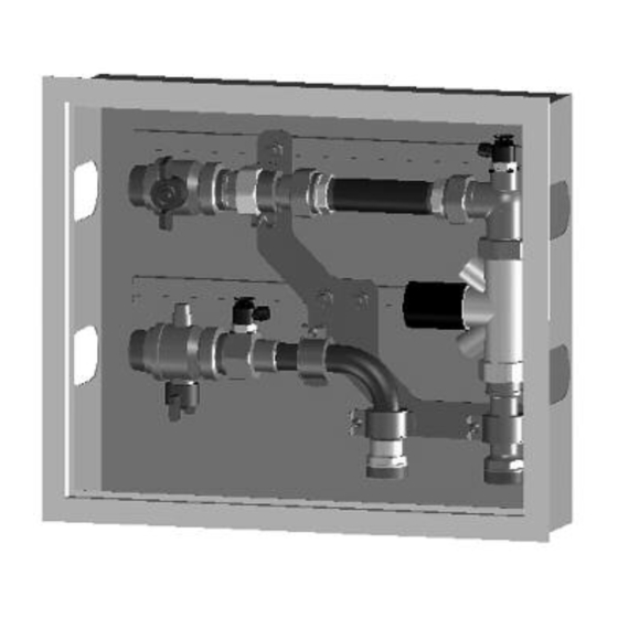
5. Filet F1 cu garnitură plată 6. Piesă de legătură pentru contor 5. Montaj 5.1. Conținutul livrat Cod art.: 1022668 Racordare laterală (fig.: 4.1): Pentru tur: – robinet sferic cu racord pentru senzor de temperatură M10 x 1, ventil de aerisire/go- lire, cot pentru țeavă... -
Page 4: Montajul „Floorbox
Instrucțiuni de montaj și utilizare „Floorbox“ 5.4. Aerisirea Imediat după recepția mărfii, verificați dacă produsul nu a fost deteriorat în timpul Aerisirea se poate face chiar și în timpul func- transportului. ționării încălzirii cu ajutorul ventilelor de aerisi- Verificați capacele de protecție dacă sunt in- re și golire ale „Floorbox“, precum și ale „Uni- tacte. -
Page 5: Operarea
Presetarea se poate determina cu ajutorul lă și contor de laterală software-ului Oventrop pentru calcularea in- energie termică stalației de țevi. Reglarea valorii rezultate se face conform instrucțiunilor ventilului de echili- brare. Nr. circ. de încăl- În cazul calculului manual al instalației, trebuie... -
Page 6: Diagrame
Instrucțiuni de montaj și utilizare „Floorbox“ 7. Diagrame Calcul: „Floorbox“ „Floorbox“ cu cu racor- racordare late- dare late- rală și contor de energie termică rală Pierdere de pre- siune „Floorbox“ cu racordare 2 mbar 2 mbar laterală (diagrama 7.1) Pierdere de presiune contor de energie 125 mbar ––... - Page 7 Valves, controls + systems ”Floorbox“ Installation and operating instructions Item no. 1022668 lateral connection Item no. 1022669 lower connection For an overview of our global presence visit www.oventrop.com. Before initial operation, please examine condition and function of system components, control,...
-
Page 8: General Information
Installation and operating instructions “Floorbox“ 3.2 Performance data 1. General information Max. working pressure: 10 bar 1.1 Information regarding operating Max. differential pressure: 1 bar instructions Max. working temperature: 100°C These operating instructions help the trades- value: 6.6 m /h (the k value of the double man to install, put into operation and service regulating and commissioning valve “Hycocon... -
Page 9: Construction And Function
5. G 1 flat sealing 5. Installation and assembly 6. Meter stool piece 5.1 Extent of supply Item no. 1022668 Lateral connection (illustr. 4.1) For the supply: – Ball valve with temperature sensor connec- tion M 10 x 1, venting and flushing valve, pipe elbow and connection fitting (pos. -
Page 10: Installation Of "Floorbox
Installation and operating instructions “Floorbox“ Upon receipt, please check delivery for 5.4 Bleeding possible damages caused during transport. The venting and flushing valves of the “Floorbox” Carry out visual check of the protection caps for as well as those of the succeeding “Unibox” damages. -
Page 11: Operation
6.2 Calculation example to the design. Given: “Floorbox“ “Floorbox“ As for the Oventrop “Floorbox”, the hydronic lateral lateral balancing is carried out with the help of the connection connection double regulating and commissioning valve with heat meter “Hycocon VTZ”. -
Page 12: Charts
Installation and operating instructions “Floorbox“ 7. Charts Calculation: “Floorbox“ “Floorbox“ lateral lateral connection connection with heat meter Pressure loss “Floorbox” lateral 2 mbar 2 mbar connection (chart 7.1) Pressure loss heat –– 125 mbar meter (example) Pump pressure 490 mbar 490 mbar less –... - Page 13 Robinetterie «haut de gamme» + Systèmes «Floorbox» Instructions de montage et mode d’emploi Réf. 1022668 raccordement latéral Réf. 1022669 raccordement par le bas Vous trouverez une vue d’ensemble des inter- locuteurs dans le monde entier sur www.oventrop.com. Avant la mise en service, vérifier le bon état des composants du système, de la commande, des interrupteurs d’urgence et des dispositifs de sécurité...
-
Page 14: Informations Générales
Instructions de montage et mode d’emploi «Floorbox» 3.2 Données techniques 1. Informations générales Pression de service max.: 10 bars 1.1 Informations concernant les instructions Pression différentielle max.: 1 bar de montage et le mode d’emploi Température de service max.: 100°C Ce mode d’emploi sert au montage, à... -
Page 15: Construction Et Fonctionnement
5. Raccordement G 1 à joint plat 5. Installation et montage 6. Pièce d’ajustage pour compteur 5.1 Fourniture Réf. 1022668 Raccordement latéral (illustr. 4.1): Pour l’aller: – Robinet à tournant sphérique avec raccorde- ment pour sonde de température M 10 x 1, robinet de purge et de rinçage, coude et... -
Page 16: Installation Du "Floorbox
Instructions de montage et mode d’emploi «Floorbox» Dès réception, veuillez contrôler le bon 5.4 Purge état de la marchandise. Vérifier le bon état des L’installation peut être purgée, même en pleine capuchons de protection. Vérifier que les période de service, moyennant les robinets de intérieurs de robinet ne comportent pas de purge et de rinçage du «Floorbox»... -
Page 17: Réglages
Le préréglage peut être déterminé à l’aide du raccordement raccordement logiciel de calcul de réseaux hydrauliques latéral latéral avec Oventrop. Le réglage de la valeur calculée se compteur de fait selon les instructions livrées avec le robinet calories d’équilibrage. Nombre des Lors d’un calcul de l’installation à... -
Page 18: Diagrammes
Instructions de montage et mode d’emploi «Floorbox» 7. Diagrammes Calcul: «Floorbox» «Floorbox» raccorde- raccordement ment latéral avec latéral compteur de calories Perte de charge «Floorbox» raccordement 2 mbars 2 mbars latéral (diagramme 7.1) Perte de charge compteur de –– 125 mbars calories (exemple) Pression de 490 mbars...
Need help?
Do you have a question about the 1022668 and is the answer not in the manual?
Questions and answers