Table of Contents
Advertisement
Quick Links
Advertisement
Table of Contents

Related Manuals for SystemAir S-SA1


Summary of Contents for SystemAir S-SA1
- Page 1 S-SA1 Smoke Control Damper - AAsingle Handbook...
-
Page 2: Table Of Contents
2/47 | S-SA1 Table of Contents Overview ............3 Technical Parameters . -
Page 3: Overview
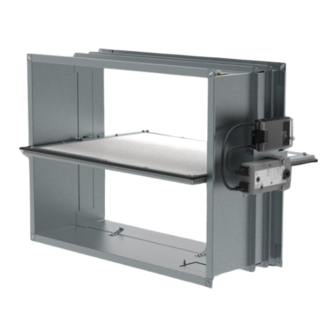
“closed” position. Power is necessary for the smoke control dampers. S-SA1 dampers are designed for on a duct installations ended with grille, not in the wall or ceiling. The “Installation Methods” section shows the types of installations that are permitted. - Page 4 Design The casing of the S-SA1 is made of a galvanized sheet metal. Blades are made from calcium silicate boards with a silicone rubber gasket which prevent leaks of heat or smoke. The casing has flange on two sides with holes for screws to attach to sheet-metal duct flanges.
- Page 5 P6 - Holder for communication unit (without unit installed only for B24-W activation type) P7 - Inspection lid P8 - Product label A1 - Extension with Grille (GE1-S-SA1) is not part of S-SA1 delivery A1.1 - Extended ductwork A1.2 - Grid...
-
Page 6: Technical Parameters
6/47 | S-SA1 Technical Parameters Durability Test • Test procedure with 10000 cycles and actuator control • No change of the necessary properties. (rotation from 0° to 90°) • Test procedure with 10000 cycles and actuator control • No change of the necessary properties. - Page 7 7/47 | S-SA1 Assessed Performance 23 CE 1396 Systemair Production a.s. Hlavná 371, 900 43 Kalinkovo, Slovakia 1396-CPR-0229 S-SA1 EN 12101-8 : 2011 Smoke control damper Nominal Activation Conditions/Sensitivity Pass Response Delay (Response Time) Opening/closure time proven. Duration: <60 s / 90°...
-
Page 8: Diagrams
8/47 | S-SA1 Diagrams The pressure drop, and A-weighted total discharged sound power level depend on the nominal width and height of the damper and air flow volume at different duct pressures. The type of activation does not influence the airflow parameter, therefore only one activation type is shown in the diagrams. - Page 9 9/47 | S-SA1 S-SA1-...-B230 S-SA1-...-B24-SR Pressure drop & A-weighted sound power level in dB(A) Pressure drop & A-weighted sound power level in dB(A) 3000 5000 10000 55 dB(A) 60 dB(A) 45 dB(A) 35 dB(A) 50 dB(A) W: 1200, H: 400...
- Page 10 10/47 | S-SA1 Diagrams for Supply Air S-SA1-...-B230 S-SA1-...-B230 Pressure drop & A-weighted sound power level in dB(A) Pressure drop & A-weighted sound power level in dB(A) 1000 2000 W: 400, H: 200 W: 400, H: 400 W: 200, H: 300...
- Page 11 11/47 | S-SA1 S-SA1-...-B230 S-SA1-...-B24-SR Pressure drop & A-weighted sound power level in dB(A) Pressure drop & A-weighted sound power level in dB(A) 3000 5000 10000 50 dB(A) W: 200, H: 200, 50 % 45 dB(A) W: 1200, H: 400...
- Page 12 12/47 | S-SA1 Diagrams for Extract with GE1-S-SA1 Accessory S-SA1-...-B230 S-SA1-...-B230 Pressure drop & A-weighted sound power level in dB(A) Pressure drop & A-weighted sound power level in dB(A) 1000 2000 W: 400, H: 400 W: 400, H: 200 W: 200, H: 200...
- Page 13 13/47 | S-SA1 S-SA1-...-B230 S-SA1-...-B24-SR Pressure drop & A-weighted sound power level in dB(A) Pressure drop & A-weighted sound power level in dB(A) 2000 5000 10000 50 dB(A) W: 200, H: 200, 0 % 60 dB(A) W: 200, H: 200, 50 %...
- Page 14 14/47 | S-SA1 Diagrams for Supply with GE1-S-SA1 Accessory S-SA1-...-B230 S-SA1-...-B230 Pressure drop & A-weighted sound power level in dB(A) Pressure drop & A-weighted sound power level in dB(A) 1000 2000 W: 400, H: 200 W: 400, H: 400 W: 200, H: 200...
- Page 15 15/47 | S-SA1 S-SA1-...-B230 S-SA1-...-B24-SR Pressure drop & A-weighted sound power level in dB(A) Pressure drop & A-weighted sound power level in dB(A) 3000 5000 10000 50 dB(A) 55 dB(A) 60 dB(A) W: 200, H: 200, 25 % W: 1200, H: 400...
- Page 16 16/47 | S-SA1 Legend: Pa - Pressure drop (p /h; l/s - Air flow volume (q...
-
Page 17: Dimensions & Weights
17/47 | S-SA1 Dimensions & Weights Dimensions of S-SA1 (mm) S-SA1... ≤130 (H>300) ≤200 (H≤300) W-12 W+40 H (mm) S-SA1 -141 -116... - Page 18 18/47 | S-SA1 Dimensions of GE1-S-SA1 GE1-S-SA1... H≤400 W+40 W-12 ≤110 (H>300) ≤200 (H≤300) (mm) GE1-S-SA1... H>400 W+40 W-12 ≤130 W+47* (mm) NOTE: *Accessory GE1-S-SA1 sold separately. GE1-S-SA1 is not part of the S-SA1 delivery. H (mm) GE1-S-SA1...
- Page 19 19/47 | S-SA1 Free Area of S-SA1 Without Grille W (mm) 1000 1100 1200 0,030 0,039 0,047 0,055 0,063 0,071 0,079 0,095 0,111 0,040 0,050 0,061 0,072 0,082 0,093 0,103 0,125 0,146 0,167 0,049 0,062 0,075 0,089 0,102 0,115 0,128 0,154 0,180 0,206 0,233...
- Page 20 37,2 40,6 44,0 48,4 51,8 55,3 58,6 33,1 34,9 36,7 40,3 44,0 48,6 51,6 54,7 57,9 61,1 BST... m + 0,7kg NOTE: For activation types BST... add communication unit weight of 0,7 kg to the weight of S-SA1 (see table).
-
Page 21: Ordering Code
21/47 | S-SA1 Ordering Codes S-SA1- × W - Width Dimension 200 mm, 250 mm, 300 mm, 350 mm, 400 mm, 450 mm, 500 mm, 600 mm, 700 mm, 800 mm, 900 mm, 1000 mm, 1100 mm, 1200 mm H - Height Dimensions... -
Page 22: Product Handling
- fire - other damage Ensure that installation is performed by a trained person. The S-SA1 is made of boards and sheet metal. Thus considered fragile. Be careful when you move the smoke control damper. Two people are necessary to move the dampers and put them onto the duct and/or hangers. It is necessary to move the bigger dampers with suitable lifting... - Page 23 23/47 | S-SA1...
- Page 24 24/47 | S-SA1 (mm) ≤50 (mm) ≤30 (mm) ≤50 (mm) ≤50...
- Page 25 1 - Smoke control damper S-SA1 2 - Connected ductwork tested according to EN 1366-9 A1 - Extension with Grille (GE1-S-SA1) is not part of S-SA1 delivery F1 - Screw M8×20 mm (e.g. DIN 933) P4 - Holder for actuator...
-
Page 26: Installation
26/47 | S-SA1 Installation Methods Warning • Suspension systems longer than 1,5 m require fire-resistant insulation • Obey the applicable regulations and standards of the country that this product will be installed in • Make sure that only approved personnel performs the installation •... - Page 27 27/47 | S-SA1 Installation DMV Vertically Oriented Damper, in the Metal Duct 1. Prepare the duct connection and the damper hangers. a. Clean the connection surfaces. Make sure that the surfaces are even. CAUTION: The product label must remain clean and readable.
- Page 28 Legend for Installation DMV 1 - Smoke control damper S-SA1 2 - Connected ductwork tested according to EN 1366-9 A1 - Extension with Grille (GE1-S-SA1) is not part of S-SA1 delivery F1 - Screw M8×20 mm (e.g. DIN 933) Damper Minimum Distances (mm) S-SA1...
- Page 29 29/47 | S-SA1 Installation D1V Vertically Oriented Damper, on the Duct 1. Prepare the duct connection and the damper hangers. a. Clean the connection surfaces. Make sure that the surfaces are even. CAUTION: The product label must remain clean and readable.
- Page 30 ≤50 Legend for Installation D1V 1 - Smoke control damper S-SA1 2 - Connected ductwork tested according to EN 1366-9 A1 - Extension with Grille (GE1-S-SA1) is not part of S-SA1 delivery F1 - Screw M8×20 mm (e.g. DIN 933)
- Page 31 31/47 | S-SA1 Damper Minimum Distances (mm) S-SA1... GE1-S-SA1... ≥200 ≥100 ≥100 ≤200 (H≤300) ≥200 ≤130 (H>300) ≥75...
- Page 32 • Stop the power supply before you do work on electrical equipment • Only approved electricians can do work on the electrical system To access the electrical parts of this product follow instructions in "Product Handling" section Actuator Size Map of S-SA1 W (mm) BEN... (15 Nm) BEE...
-
Page 33: Electrical Parameters
33/47 | S-SA1 Electrical Parameters for Type of Activation and Actuator T (Nm) NV (V) F (Hz) CO (W) CR (W) WS (VA) BEN230 Imax 4 A @ 5 ms B230 BEE230 AC 230 50/60 Imax 4 A @ 5 ms... - Page 34 34/47 | S-SA1 Type of Activation B230 • The circuit switch between wires 2 and 3 is not part of the damper supply. • When the power supply is connected to wires 1 and 3, the actuator moves to the OPEN position.
- Page 35 35/47 | S-SA1 Type of Activation B24 • The circuit switch between wires 2 and 3 is not part of the damper supply. • When the power supply is connected to wires 1 and 3, the actuator moves to the OPEN position.
- Page 36 36/47 | S-SA1 Type of Activation B24-W This type of activation has cable connectors (C1 and C2) for the supply and communication unit (the communication unit is not part of the mechanism). AC/DC 24 V S4 S5 S2 S3 S6...
- Page 37 37/47 | S-SA1 Type of Activation B24-SR This type of activation has modulating actuator that can be used for balancing/air flow control. AC/DC 24 V DC (0)2 V ... 10 V DC 2 V ... 10 V S1 S2 S3 S4 S5 S6 <5°...
- Page 38 38/47 | S-SA1 Type of Activation BST0 • The actuator and the control module are factory wired. • Connect the supply voltage to the connecting cable (approx. 1 m, with ferrules). • The 2-wire cable a|b to the BKSE24-6 is connected to terminals 6 and 7 (screw terminals for 2 x 1.5 mm^2 wire).
- Page 39 39/47 | S-SA1 Legend for Activation Type BST0 L (+) - Brown N (-) - Blue 1) - Supply voltage cable 2) - 2-wire cable a/b - Connection to e.g. BKSE24-6...
- Page 40 40/47 | S-SA1 Type of activation BST1 IMPORTANT: Danger of electric shock! Parallel circuits, i.e. a smoke detector on multiple slave devices are not allowed! Switch off the power supply before working on any electrical equipment. Allow only qualified electricians to work on the electrical system.
- Page 41 41/47 | S-SA1 X4 - 4-pin spring terminal: Connection for smoke detector. • 1- (+) DC 24 V / max. 30 mA. • 2- GND. • 3- IN1 (external relay contact 1). • 4- IN2 (external relay contact 2). X6 - 6-pin connector: damper actuator (position limit switches).
- Page 42 42/47 | S-SA1 Type of Activation BST10 IMPORTANT: Danger of electric shock! The BKNE230-24-PL may only be used with a designated master (e.g. BKS64- PL). Switch off the power supply before working on any electrical equipment. Allow only qualified electricians to work on the electrical system.
- Page 43 43/47 | S-SA1 Legend for Activation Type BST10 X6 and X300 connector terminals are arranged so that only either a conventional actuator or a Belimo Top-Line actuator can be connected. X200 - 2+2-pin spring terminal: (50/60Hz) AC 230 V with Powerline signal...
-
Page 44: Operation Manual
44/47 | S-SA1 Operation Manual Functionality Check Before and after you install the damper, make sure that the dampers functionality is checked. The functionality is checked by: 1. Refer to the “Electrical connections” section to prepare the actuator connection. 2. Opening the damper: •... - Page 45 45/47 | S-SA1 90° ≤60s 0° Damper Inspection CAUTION: Never perform inspection when there is air flowing in the duct connected to the smoke control damper. Do not change the dampers or their structure without the approval of the manufacturer.
- Page 46 We reserve the right to make any changes to the product without prior notice, provided that these changes do not affect the quality of the product and the required parameters. Current information on all products is available on design.systemair.com.
- Page 47 [object Object] • 2023-06-06 • Handbook_S_SA1_en-GB • Working • Original instructions...
Need help?
Do you have a question about the S-SA1 and is the answer not in the manual?
Questions and answers