Table of Contents
Advertisement
Quick Links
Advertisement
Table of Contents

Related Manuals for SystemAir S-BA2


Summary of Contents for SystemAir S-BA2
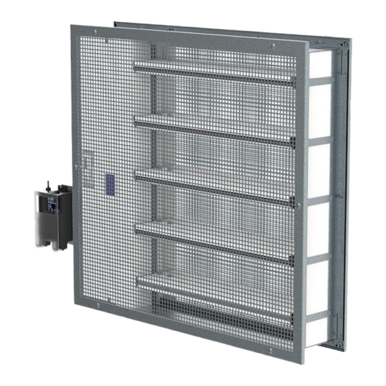
- Page 1 S-BA2 Smoke Control Damper - AA multi Handbook...
-
Page 2: Table Of Contents
2/55 | S-BA2 Table of Contents Overview ............3 Technical Parameters . -
Page 3: Overview
S-BA2 dampers have an actuator without a spring. Thus, they have two safety positions: an “open” position and a “closed” one. Power is necessary for the smoke control dampers. - Page 4 Design The casing and the blades of the S-BA2 are made of a galvanized sheet metal. A foam seal with an intumescent seal that prevents leaks of heat or smoke. The casing has flanges on two sides with a thread to attach to sheet-metal duct flanges.
- Page 5 5/55 | S-BA2 Product Parts S-BA2-... P9 P10 Legend: P1 - Damper casing P2 - Damper blade P3 - Actuator P4 - Supply and communication unit (only for BST0 activation type) P5 - Holder for communication unit (only for B24T-W activation type)
-
Page 6: Technical Parameters
6/55 | S-BA2 Technical Parameters Durability Test • Test procedure with 10000 cycles and actuator control • No change of the necessary properties. (rotation from 0° to 90°) • Test procedure with 10000 cycles and actuator control • No change of the necessary properties. - Page 7 Make sure that the damper blade is in the closed position during transportation and protected from weather disruptions. The storage of the smoke control damper must be indoors. Assessed Performance 19 CE 1396 Systemair Production a.s. Hlavná 371, 900 43 Kalinkovo, Slovakia 1396-CPR-0202 S-BA2...
-
Page 8: Diagrams
8/55 | S-BA2 Diagrams The pressure drop, and A-weighted total discharged sound power level depend on the nominal width and height of the damper and air flow volume at different duct pressures. The type of activation does not influence the airflow parameter, therefore only one activation type is shown in the diagrams. - Page 9 9/55 | S-BA2 Diagrams for Supply Air, Grille Type: 00 S-BA2-...-00- S-BA2-...-00- Pressure drop & A-weighted sound power level in dB(A) Pressure drop & A-weighted sound power level in dB(A) 1000 1000 2000 W: 200, H: 250 W: 200, H: 500...
- Page 10 10/55 | S-BA2 Diagrams for Extract Air, Grille Types: 01 & 02 S-BA2-...-01- S-BA2-...-01- Pressure drop & A-weighted sound power level in dB(A) Pressure drop & A-weighted sound power level in dB(A) 1000 5000 W: 200, H: 1000 W: 200, H: 250...
- Page 11 11/55 | S-BA2 Diagrams for Supply Air, Grille Types: 01 & 02 S-BA2-...-01- S-BA2-...-01- Pressure drop & A-weighted sound power level in dB(A) Pressure drop & A-weighted sound power level in dB(A) 1000 1000 2000 W: 200, H: 250 W: 600, H: 250...
- Page 12 12/55 | S-BA2 Diagrams for Extract Air, Grille Types: 11 & 22 S-BA2-...-11- S-BA2-...-11- Pressure drop & A-weighted sound power level in dB(A) Pressure drop & A-weighted sound power level in dB(A) 1000 W: 600, H: 250 W: 200, H: 500...
- Page 13 13/55 | S-BA2 Supply Diagrams for Grille Types: 11 & 22 S-BA2-...-11- S-BA2-...-11- Pressure drop & A-weighted sound power level in dB(A) Pressure drop & A-weighted sound power level in dB(A) 1000 1000 2000 W: 600, H: 500 W: 600, H: 250...
-
Page 14: Dimensions
14/55 | S-BA2 Dimensions & Weights Dimensions (mm) W+20 S-BA2-... W+222 125* W+230* 145* NOTE: *Inclusive grille... - Page 15 15/55 | S-BA2 Free area of S-BA2 without grille W (mm) 150 175 200 225 250 280 300 315 350 355 400 450 500 550 560 600 630 650 700 710 750 800 1000 Free area of grille W (mm)
- Page 16 16/55 | S-BA2 Weights of S-BA2 without grille W (mm) m (kg) 150 175 200 225 250 280 300 315 350 355 400 450 500 550 560 600 630 650 700 710 750 800 1000 Weights of grille W (mm)
-
Page 17: Ordering Code
17/55 | S-BA2 Ordering Codes W - Width Dimension 150 mm, 175 mm, 200 mm, 225 mm, 250 mm, 280 mm, 300 mm, 315 mm, 350 mm, 355 mm, 400 mm, 450 mm, 500 mm, 550 mm, 560 mm, 600 mm, 630 mm, 650 mm, 700 mm, 710 mm, 750 mm, 800 mm. -
Page 18: Product Handling
- fire. - other damage. Ensure that installation is performed by a trained person. The S-BA2 is made of boards and sheet metal. Thus considered fragile. Be careful when you move the smoke control damper. Two persons are necessary to move the smaller dampers and put them in the installation opening. It is necessary to move the bigger dampers with suitable... - Page 19 19/55 | S-BA2...
- Page 20 20/55 | S-BA2...
- Page 21 21/55 | S-BA2...
- Page 22 22/55 | S-BA2 Legend for Product Handling 1 - Smoke control damper S-BA2 2 - Connected metal ductwork 5 - Grille 8 - Support/brick, metal stud or wood stud (not part of damper) F3 - Self-tapping screw size 4,2 ... 4,8; length 80 mm (e.g. DIN 7981C/DIN 7982C)
-
Page 23: Installation
23/55 | S-BA2 Installation Methods EI 90 (v i ↔ o) S1000 C AAmulti S-BA2 1 Wet 150 × 250 ..800 × 1000 EI 90 (v i ↔ o) ≥ 125 mm ≥ 125 mm S1000 C AAmulti... - Page 24 • The minimum distance between the smoke control damper and the adjacent wall or ceiling must be 75 mm. • If you install the S-BA2 in a smoke and fire partition structure, do a check of the damper blades. Make sure that the damper blades in its closed position are in this structure.
- Page 25 25/55 | S-BA2 Installation 1. Wet - Installation in the Wall Procedure to fill with Plaster, Mortar, or Concrete 1. Prepare the opening in the Wall: NOTE: The dimensions of the openings are the result of the nominal dimensions of the damper with added clearance.
- Page 26 26/55 | S-BA2 12,5 ≥50 (mm) (mm) >125 >125 >12,5 >50 (mm) (mm)
- Page 27 27/55 | S-BA2 12,5 ≥50 (mm) (mm) >125 >125 >12,5 >50 (mm) (mm)
- Page 28 28/55 | S-BA2 12,5 ≥50 (mm) (mm) >125 (mm)
- Page 29 ≥75 ≥200 (mm) Legend for Installation 1 Wet 1 - Smoke control damper S-BA2 2 - Connected metal ductwork 3 - Concrete/masonry/cellular concrete wall or ceiling 4 - Flexible (plasterboard) wall 4a - 2 layers of plasterboard fireproof plate type F, EN 520 4b - Vertical CW –...
- Page 30 30/55 | S-BA2 Installation 3. Soft - Installation in the Wall Procedure to Fill with Mineral Wool 1. Prepare the opening in the Wall: NOTE: The dimensions of the openings are the result of the nominal dimensions of the damper with added clearance.
- Page 31 31/55 | S-BA2 12,5 ≥50 (mm) (mm) >125 >125 >12,5 >50 (mm) (mm)
- Page 32 32/55 | S-BA2 12,5 ≥50 (mm) (mm) >125 >125 >12,5 >50 (mm) (mm)
- Page 33 33/55 | S-BA2 12,5 ≥50 (mm) (mm) >125 (mm)
- Page 34 34/55 | S-BA2 >125 >12,5 >50 (mm) >125 (mm) ≥125 (mm)
- Page 35 ≥75 ≥200 (mm) Legend for Installation 3. Soft 1 - Smoke control damper S-BA2 2 - Connected metal ductwork 3 - Concrete/masonry/cellular concrete wall or ceiling 4 - Flexible (plasterboard) wall 4a - 2 layers of plasterboard fireproof plate type F, EN 520 4b - Vertical CW –...
- Page 36 Installation DMH Horizontally Oriented Damper, in the Metal Duct The S-BA2 smoke control damper can be installed on these types of ductwork: - “single” ductwork (the tests refer to EN 1366-9) - “multi” ductwork (the tests refer to EN 1366-8).
- Page 37 ≥80 W × H (mm) Legend for installation DMH 1 - Smoke control damper S-BA2 2 - Connected metal ductwork 5 - Grille F2 - Screw M6×20-25 mm, maximum fixing torque is 4,5 Nm NOTE: Following insulation system can be replaced for another smoke control duct system with equal or higher thickness and/or equal or higher bulk density.
- Page 38 Installation DMV Vertically Oriented Damper, in the Metal Duct The S-BA2 smoke control damper can be installed on these types of ductwork: - “single” ductwork (the tests refer to EN 1366-9) - “multi” ductwork (the tests refer to EN 1366-8).
- Page 39 ≤125 ≥80 W × H Legend for Installation DMV 1 - Smoke control damper S-BA2 2 - Connected metal ductwork 5 - Grille F2 - Screw M6×20-25 mm, maximum fixing torque is 4,5 Nm NOTE: Following insulation system can be replaced for another smoke control duct system with equal or higher thickness and/or equal or higher bulk density.
- Page 40 Installation D1H, D2H Horizontally Oriented Damper, on the Duct The S-BA2 smoke control damper can be installed on these types of ductwork: - “single” ductwork (the tests refer to EN 1366-9) - “multi” ductwork (the tests refer to EN 1366-8).
- Page 41 41/55 | S-BA2 (D1H) (W+180) × H ≤50 ≤125 ≤125 W × H ≥80 (mm) (D1H) (mm) ✓ Y (D2H) H × W ≤50 ≤125 ≤125 ≥80 (mm) X (D2H) ≤125 ≤125 (mm) ✓...
- Page 42 42/55 | S-BA2 Legend for Installation D1H, D2H 1 - Smoke control damper S-BA2 2 - Connected metal ductwork 5 - Grille F2 - Screw M6×20-25 mm, maximum fixing torque is 4,5 Nm NOTE: Following insulation system can be replaced for another smoke control duct system with equal or higher thickness and/or equal or higher bulk density.
- Page 43 Installation D1V Vertically Oriented Damper, on the Duct The S-BA2 smoke control damper can be installed on these types of ductwork: - “single” ductwork (the tests refer to EN 1366-9) - “multi” ductwork (the tests refer to EN 1366-8). This section does not give information about duct hanger rules. These rules are related to the weight of the duct and they must have static approval.
- Page 44 44/55 | S-BA2 Y (D1V) (mm) ≥80 X (D1V) (mm) ≤125 ≤125 ≤50 W × H ≥80 Y (D1V) (mm) X (D1V) (mm) ≤50 ≤125 ≤125 W × H ≥80...
- Page 45 45/55 | S-BA2 Legend for Installation D1V 1 - Smoke control damper S-BA2 2 - Connected metal ductwork 5 - Grille F2 - Screw M6×20-25 mm, maximum fixing torque is 4,5 Nm NOTE: Following insulation system can be replaced for another smoke control duct system with equal or higher thickness and/or equal or higher bulk density.
-
Page 46: Electrical Parameters
46/55 | S-BA2 Electrical Connections WARNING • Risk of electric shock. • Stop the power supply before you do work on electrical equipment. • Only approved electricians can do work on the electrical system. To access the electrical parts of this product follow instructions in "Product Handling" section. - Page 47 47/55 | S-BA2 Type of Activation B230 • The circuit switch between wires 2 and 3 is not part of the damper supply. • When the power supply is connected to wires 1 and 3, the actuator moves to the OPEN position.
- Page 48 48/55 | S-BA2 Type of Activation B24 • The circuit switch between wires 2 and 3 is not part of the damper supply. • When the power supply is connected to wires 1 and 3, the actuator moves to the OPEN position.
- Page 49 49/55 | S-BA2 Type of Activation B24-W This type of activation has cable connectors for the supply and communication unit (the communication unit is not part of the mechanism). • The circuit switch between wires 2 and 3 is not part of the damper supply.
- Page 50 50/55 | S-BA2 Type of Activation B24-SR 24V AC/DC Belimo Actuator, modulated (0)2..10V • When power supply is connected to wires 1 and 3, actuator drives to position OPEN. • When power supply is connected to wires 1 and 2, actuator drives to position CLOSED.
- Page 51 51/55 | S-BA2 Type of Activation BST0 • The actuator and the control module are factory wired. • Connect the supply voltage to the connecting cable (approx. 1 m, with ferrules). • The 2-wire cable a/b to the BKSE24-6 is connected to terminals 6 and 7 (screw terminals for 2 x 1.5 mm^2 wire).
-
Page 52: Operation Manual
52/55 | S-BA2 Operation Manual Functionality Check Before and after you install the damper, make sure that the dampers functionality is checked. The functionality is checked by: 1. Refer to the “Electrical connections” section to prepare the actuator connection. 2. Opening the damper: •... - Page 53 53/55 | S-BA2 Do not change the dampers or their structure without the approval of the manufacturer. The actuator keeps the dampers on stand-by during their life cycle. The operator obeys the applicable regulations and standards to do regular checks of the dampers. The recommended minimum interval for the inspection checks is 6 months.
- Page 54 54/55 | S-BA2 Supplement If you find differences from the terms and the technical specifications that are in this manual, speak to the manufacturer. We reserve the right to make changes to the product without notice.
- Page 55 Systemair DESIGN • 2021-09-16 • Handbook_S_BA2_en-GB...
Need help?
Do you have a question about the S-BA2 and is the answer not in the manual?
Questions and answers