Table of Contents
Advertisement
Quick Links
Advertisement
Table of Contents

Related Manuals for SystemAir S-SA2


Summary of Contents for SystemAir S-SA2
- Page 1 S-SA2 Smoke Control Damper - AAmulti Handbook...
-
Page 2: Table Of Contents
2/68 | S-SA2 Table of Contents Overview ............3 Technical Parameters . -
Page 3: Overview
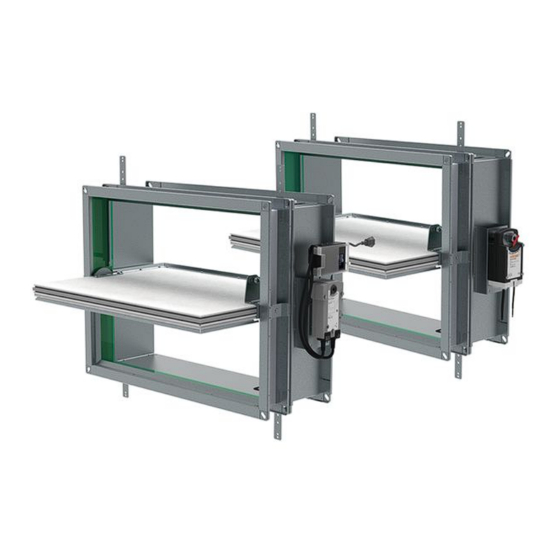
S-SA2 dampers have an actuator without a spring. Thus, they have two safety positions: an “open” position and a “closed” position. Power is necessary for the smoke control dampers. - Page 4 Design The casing of the S-SA2 is made of a galvanized sheet metal. Blades are made from calcium silicate boards. A foam seal, silicone rubber gasket with an intumescent seal prevent leaks of heat or smoke. The casing has flanges on two sides with holes for screws to attach to sheet-metal duct flanges.
- Page 5 5/68 | S-SA2 Product Parts S-SA2... Legend P1 - Damper casing P2 - Damper blade P3 - Bendable hanger P4 - Actuator P5 - Supply and communication unit (only for BST0, GST0, BST1, BST10 activation type) P6 - Holder for communication unit (without unit installed only for B24-W activation type)
-
Page 6: Technical Parameters
6/68 | S-SA2 Technical Parameters Durability Test • Test procedure with 10000 cycles and actuator control • No change of the necessary properties. (rotation from 0° to 90°) • Test procedure with 10000 cycles and actuator control • No change of the necessary properties. - Page 7 7/68 | S-SA2 Assessed Performance 15 CE 1396 Systemair Production a.s. Hlavná 371, 900 43 Kalinkovo, Slovakia 1396-CPR-0112 S-SA2 EN 12101-8 : 2011 Smoke control damper Nominal Activation Conditions/Sensitivity Pass Response Delay (Response Time) Opening/closure time proven. Duration: <60 s / 90°...
-
Page 8: Diagrams
8/68 | S-SA2 Diagrams The pressure drop, and A-weighted total discharged sound power level depend on the nominal width and height of the damper and air flow volume at different duct pressures. The type of activation does not influence the airflow parameter, therefore only one activation type is shown in the diagrams. - Page 9 9/68 | S-SA2 S-SA2-...- S-SA2-...- Pressure drop & A-weighted sound power level in dB(A) Pressure drop & A-weighted sound power level in dB(A) 2000 5000 10000 8000 10000 20000 W: 1200, H: 400 W: 1200, H: 800 W: 1600, H: 900...
- Page 10 10/68 | S-SA2 S-SA2-...- S-SA2-...- Pressure drop & A-weighted sound power level in dB(A) Pressure drop & A-weighted sound power level in dB(A) 1000 5000 1000 2000 5000 W: 800, H: 250 W: 600, H: 200 W: 800, H: 600...
- Page 11 11/68 | S-SA2 Diagrams for Extract Air With D1-S-SA2 Accessory S-SA2-...- S-SA2-...- Pressure drop & A-weighted sound power level in dB(A) Pressure drop & A-weighted sound power level in dB(A) 1000 2000 W: 400, H: 600 W: 400, H: 200...
- Page 12 10000 20000 m³/h 10000 20000 30000 m³/h Diagrams for Supply Air With D1-S-SA2 Accessory S-SA2-...- S-SA2-...- Pressure drop & A-weighted sound power level in dB(A) Pressure drop & A-weighted sound power level in dB(A) 1000 2000 W: 400, H: 200...
- Page 13 13/68 | S-SA2 S-SA2-...- S-SA2-...- Pressure drop & A-weighted sound power level in dB(A) Pressure drop & A-weighted sound power level in dB(A) 1000 2000 1000 5000 W: 600, H: 200 W: 800, H: 250 W: 600, H: 600 W: 800, H: 600...
-
Page 14: Dimensions & Weights
14/68 | S-SA2 Dimensions & Weights Dimensions (mm) S-SA2... ≤200 (H≤300) ≤125 (H>300) (125) W+60 H (mm) 1000 -155 -130 -105 Free Area W (mm) 200 250 300 350 400 450 500 600 700 800 900 1000 1100 1200 1300 1400 1500 1600... - Page 15 33,2 35,4 39,7 44,1 48,5 53,0 58,7 63,1 67,5 71,9 76,8 80,7 85,1 1000 38,2 43,0 47,8 52,5 58,7 63,4 68,2 73,0 77,8 83,2 87,4 92,2 BST.../GST... m +0,7 kg NOTE: For activation types BST.../GST... add communication unit weight of 0,7 kg to the weight of S-SA2 (see table).
-
Page 16: Ordering Code
16/68 | S-SA2 Ordering Codes W - Width Dimension 200 mm, 250 mm, 300 mm, 350 mm, 400 mm, 450 mm, 500 mm, 600 mm, 700 mm, 800 mm, 900 mm, 1000 mm, 1100 mm, 1200 mm, 1300 mm, 1400 mm, 1500 mm, 1600 mm... -
Page 17: Product Handling
- fire. - other damage. Ensure that installation is performed by a trained person. The S-SA2 is made of boards and sheet metal. Thus considered fragile. Be careful when you move the smoke control damper. Two persons are necessary to move the dampers and put them in the installation opening. It is necessary to move the bigger dampers with suitable lifting... - Page 18 18/68 | S-SA2...
- Page 19 19/68 | S-SA2 ≥...
- Page 20 20/68 | S-SA2 Legend for Product Handling 1 - Smoke control damper S-SA2 2 - Connected ductwork tested according to EN 1366-9 4 - Supporting construction 7 - Support/brick, metal stud or wood stud (not part of damper) F2 - Screw with minimum dimensions of 5,5 mm diameter and 80 mm length based on the structure type, (e.g.: DIN 7981C/DIN 7982C;...
-
Page 21: Installation
• The minimum distance between the smoke control damper and the adjacent wall or ceiling must be 75 mm. • If you install the S-SA2 in a smoke and fire partition structure, do a check of the damper blades. Make sure that the damper blades in its closed position are in this structure. - Page 22 22/68 | S-SA2 EI 120 (v i ↔ o) S1500 C AAmulti S-SA2 ≥ 150 mm ≥ 150 mm 200 × 200 ... 1 Wet ... 1600 × 1000 EI 120 (h i ↔ o) S1500 C AAmulti ≥ 125 mm ≥...
- Page 23 23/68 | S-SA2 Installation 1. Wet Procedure to Fill with Plaster, Mortar, or Concrete 1. Prepare the opening in the supporting construction: NOTE: The dimensions of the openings are the result of the nominal dimensions of the damper with added clearance.
- Page 24 24/68 | S-SA2 (mm) ≥150 (EI120) ≥150 (EI120) (120) (300)
- Page 25 25/68 | S-SA2 (mm) ✓...
- Page 26 26/68 | S-SA2 Opening and Wall/Ceiling Preparation ≥60 mm ≥80 kg/m ≥100 mm ≥12,5 mm ≥150 mm (mm)
- Page 27 ≥75 ≥170 ≥200 Legend for Installation 1. Wet 1 - Smoke control damper S-SA2 2 - Connected ductwork tested according to EN 1366-9 3 - Concrete/masonry/cellular concrete wall or ceiling 4 - Flexible (plasterboard) wall 4a - 2 layers of plasterboard fireproof plate type F, EN 520 4b - Vertical CW –...
- Page 28 The S-SA2 smoke damper can be connected to “multi” classified ductwork made of calcium silicate boards tested according to EN 1366-8. If mounted on a duct classified with lower fire resistivity, the fire resistivity of the S-SA2 smoke control damper will be decreased to the duct level. This section does not depict duct hanger rules as those are dependent on the weight of the duct itself and must be statically approved.
- Page 29 29/68 | S-SA2 1A - Board Ductwork Connected to Damper Side Without Actuator (mm) ≥150 (EI120) ≥150 (EI120) (120) (300)
- Page 30 S-SA2 (mm) ✓ Legend for Installation 1A Wet, Connected to Board Duct 1 - Smoke control damper S-SA2 2 - Connected ductwork tested according to EN 1366-9 3 - Concrete/masonry/cellular concrete wall or ceiling 4 - Flexible (plasterboard) wall 4a - 2 layers of plasterboard fireproof plate type F, EN 520 4b - Vertical CW –...
- Page 31 31/68 | S-SA2 1B - Board Ductwork Connected to Damper Side With Actuator (mm) ≥30 ≥30 ≥150 (EI120) ≥150 (EI120) (120) (300)
- Page 32 32/68 | S-SA2 (mm) ✓ ≥30 ≥30...
- Page 33 33/68 | S-SA2 Legend for Installation 1B Wet, Connected to Board Duct 1 - Smoke control damper S-SA2 2 - Connected ductwork tested according to EN 1366-9 3 - Concrete/masonry/cellular concrete wall 4 - Flexible (plasterboard) wall 4a - 2 layers of plasterboard fireproof plate type F, EN 520 4b - Vertical CW –...
- Page 34 34/68 | S-SA2 1C - Board Ductwork Connected to Damper Side With/Without Actuator (mm) ≥30 ≥30 ≥150 (EI120) ≥150 (EI120) (120) (300)
- Page 35 35/68 | S-SA2 (mm) ✓ ≥30 ≥30...
- Page 36 36/68 | S-SA2 Legend for Installation 1C Wet, Connected to Board Duct 1 - Smoke control damper S-SA2 2 - Connected ductwork tested according to EN 1366-9 3 - Concrete/masonry/cellular concrete wall or ceiling 4 - Flexible (plasterboard) wall 4a - 2 layers of plasterboard fireproof plate type F, EN 520 4b - Vertical CW –...
- Page 37 37/68 | S-SA2 Installation 3. Soft - Installation in the Wall Procedure to Fill with Mineral Wool (up to Size 1000 × 800 mm) 1. Prepare the opening in the Wall: NOTE: The dimensions of the openings are the result of the nominal dimensions of the damper with added clearance.
- Page 38 38/68 | S-SA2 (mm) ≥150 (EI90) ≥150 (EI90) (120) (300)
- Page 39 39/68 | S-SA2 Opening and Wall/Ceiling Preparation ≥60 mm ≥80 kg/m ≥100 mm ≥12,5 mm ≥150 mm (mm)
- Page 40 ≥75 ≥170 ≥200 Legend for Installation 3. Soft 1 - Smoke control damper S-SA2 2 - Connected ductwork tested according to EN 1366-9 3 - Concrete/masonry/cellular concrete wall 4 - Flexible (plasterboard) wall 4a - 2 layers of plasterboard fireproof plate type F, EN 520 4b - Vertical CW –...
- Page 41 The S-SA2 smoke damper can be connected to “multi” classified ductwork made of calcium silicate boards tested according to EN 1366-8. If mounted on a duct classified with lower fire resistivity, the fire resistivity of the S-SA2 smoke control damper will be decreased to the duct level. This section does not depict duct hanger rules as those are dependent on the weight of the duct itself and must be statically approved.
- Page 42 42/68 | S-SA2 3A - Board Ductwork Connected to Damper Side Without Actuator (mm) ≥150 (EI90) ≥150 (EI90) (120) (300)
- Page 43 43/68 | S-SA2 Legend for Installation 3A Soft 1 - Smoke control damper S-SA2 2 - Connected ductwork tested according to EN 1366-9 3 - Concrete/masonry/cellular concrete wall 4 - Flexible (plasterboard) wall 4a - 2 layers of plasterboard fireproof plate type F, EN 520 4b - Vertical CW –...
- Page 44 44/68 | S-SA2 3B - Board Ductwork Connected to Damper Side With Actuator (mm) ≥30 ≥30 ≥150 (EI90) ≥150 (EI90) (120) (300)
- Page 45 45/68 | S-SA2 Legend for Installation 3B Soft 1 - Smoke control damper S-SA2 2 - Connected ductwork tested according to EN 1366-9 3 - Concrete/masonry/cellular concrete wall 4 - Flexible (plasterboard) wall 4a - 2 layers of plasterboard fireproof plate type F, EN 520 4b - Vertical CW –...
- Page 46 46/68 | S-SA2 3C - Board Ductwork Connected to Damper Side With/Without Actuator (mm) ≥30 ≥30 ≥150 (EI90) ≥150 (EI90) (120) (300)
- Page 47 47/68 | S-SA2 Legend for Installation 3C Soft 1 - Smoke control damper S-SA2 2 - Connected ductwork tested according to EN 1366-9 3 - Concrete/masonry/cellular concrete wall 4 - Flexible (plasterboard) wall 4a - 2 layers of plasterboard fireproof plate type F, EN 520 4b - Vertical CW –...
- Page 48 • Stop the power supply before you do work on electrical equipment. • Only approved electricians can do work on the electrical system. To access the electrical parts of this product follow instructions in "Product Handling" section. Actuator Size Map of S-SA2 W (mm) BEN... (15 Nm) BEE...
- Page 49 49/68 | S-SA2 Electrical Parameters for Type of Activation and Actuator T (Nm) NV (V) F (Hz) CO (W) CR (W) WS (VA) BEN230 Imax 4 A @ 5 ms B230 BEE230 AC 230 50/60 Imax 4 A @ 5 ms...
-
Page 50: Electrical Parameters
50/68 | S-SA2 Legend for Electrical Parameters AT - Activation type B - Belimo actuator type - Supply and communication unit G - Gruner actuator type T - Torque NV - Nominal voltage F - Frequency CO - Consumption in operation... - Page 51 51/68 | S-SA2 Type of Activation B230 • The circuit switch between wires 2 and 3 is not part of the damper supply. • When the power supply is connected to wires 1 and 3, the actuator moves to the OPEN position.
- Page 52 52/68 | S-SA2 Type of Activation G230 • Circuit switch for wire 3 is not part of the damper delivery. • Connect power supply to wire 1+2, actuator drives to position OPEN (1). Is also wire 3 connected to the power supply, actuator drives to position CLOSED (0).
- Page 53 53/68 | S-SA2 Type of Activation B24 • The circuit switch between wires 2 and 3 is not part of the damper supply. • When the power supply is connected to wires 1 and 3, the actuator moves to the OPEN position.
- Page 54 54/68 | S-SA2 Type of Activation G24 • Circuit switch for wire 3 is not part of the damper delivery. • Connect power supply to wire 1+2, actuator drives to position OPEN (1). Is also wire 3 connected to the power supply, actuator drives to position CLOSED (0).
- Page 55 55/68 | S-SA2 Type of Activation B24-W This type of activation has cable connectors (C1 and C2) for the supply and communication unit (the communication unit is not part of the mechanism). AC/DC 24 V S4 S5 S2 S3 S6...
- Page 56 56/68 | S-SA2 Type of Activation G24-W This type of activation has cable connectors (C1 and C2) for the supply and communication unit (the communication unit is not part of the mechanism). AC/DC 24 V S4 S5 S2 S3 S6...
- Page 57 57/68 | S-SA2 Type of Activation B24-SR This type of activation has modulating actuator that can be used for balancing/air flow control. AC/DC 24 V DC (0)2 V ... 10 V DC 2 V ... 10 V S1 S2 S3 S4 S5 S6 <5°...
- Page 58 58/68 | S-SA2 Type of Activation BST0 • The actuator and the control module are factory wired. • Connect the supply voltage to the connecting cable (approx. 1 m, with ferrules). • The 2-wire cable a|b to the BKSE24-6 is connected to terminals 6 and 7 (screw terminals for 2 x 1.5 mm^2 wire).
- Page 59 59/68 | S-SA2 Legend for Activation Type BST0 L (+) - Brown N (-) - Blue 1) - Supply voltage cable 2) - 2-wire cable a/b - Connection to e.g. BKSE24-6...
- Page 60 60/68 | S-SA2 Type of Activation GST0 • The actuator and the control module are factory wired. Coms Power In Power Out C B A R1 C R1 C Power Close Close Open Open CONF DAMPER OUT DAMPER OUT 1 C 2...
- Page 61 61/68 | S-SA2 Type of activation BST1 IMPORTANT: Danger of electric shock! Parallel circuits, i.e. a smoke detector on multiple slave devices are not allowed! Switch off the power supply before working on any electrical equipment. Allow only qualified electricians to work on the electrical system.
- Page 62 62/68 | S-SA2 X4 - 4-pin spring terminal: Connection for smoke detector. • 1- (+) DC 24 V / max. 30 mA. • 2- GND. • 3- IN1 (external relay contact 1). • 4- IN2 (external relay contact 2). X6 - 6-pin connector: damper actuator (position limit switches).
- Page 63 63/68 | S-SA2 Type of Activation BST10 IMPORTANT: Danger of electric shock! The BKNE230-24-PL may only be used with a designated master (e.g. BKS64- PL). Switch off the power supply before working on any electrical equipment. Allow only qualified electricians to work on the electrical system.
- Page 64 64/68 | S-SA2 Legend for Activation Type BST10 X6 and X300 connector terminals are arranged so that only either a conventional actuator or a Belimo Top-Line actuator can be connected. X200 - 2+2-pin spring terminal: (50/60Hz) AC 230 V with Powerline signal...
-
Page 65: Operation Manual
65/68 | S-SA2 Operation Manual Functionality Check Before and after you install the damper, make sure that the dampers functionality is checked. The functionality is checked by: 1. Refer to the “Electrical connections” section to prepare the actuator connection. 2. Opening the damper: •... - Page 66 66/68 | S-SA2 90° ≤60s 0° Damper Inspection CAUTION: Never perform inspection when there is air flowing in the duct connected to the smoke control damper. Do not change the dampers or their structure without the approval of the manufacturer.
- Page 67 We reserve the right to make any changes to the product without prior notice, provided that these changes do not affect the quality of the product and the required parameters. Current information on all products is available on design.systemair.com.
- Page 68 Systemair DESIGN • 2022-10-26 • Handbook_S_SA2_en-GB • Original instructions...
Need help?
Do you have a question about the S-SA2 and is the answer not in the manual?
Questions and answers