Advertisement
Quick Links
Advertisement

Related Manuals for SystemAir F-B90


Summary of Contents for SystemAir F-B90
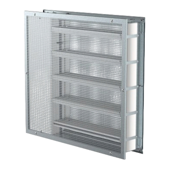
- Page 1 F-B90 Multiblade Fire damper...
-
Page 2: Table Of Contents
2/69 | F-B90 Table of Contents Overview Technical parameters Diagrams Dimensions Ordering Code Installation Electrical parameters Operation manual... -
Page 3: Overview
The fire dampers together with their installation form an integral part of the fire resistivity rating. F-B90 fire dampers are designed for the installations listed in their Data Sheet. Their installation is described in the User Manual of the fire dampers. - Page 4 4/69 | F-B90 • 11 or 22 Fire damper with two sides with sheet metal grille, Zinc coated (11) or RAL9003 Powder coated (22). Type suitable to be used as Air Transfer Grille. Activation Types • H0 Fire damper with a manual crank activation mechanism and with a spring return release mechanism activated by a fusible thermal link set to 74°C.
-
Page 5: Technical Parameters
5/69 | F-B90 Technical Parameters Durability test 50 cycles/manually operated activation mechanism – with no change of the required properties 10000 + 100 + 100 cycles/actuator operated activation mechanism – with no change of the required properties 10000 cycles, actuator controlled for "SR" actuator (45 … 60 degrees rotation) - with no change of the required properties... - Page 6 6/69 | F-B90 Belimo: BF230-T, BF24-T, BF24-SR-T, BFN230-T, BFN24-T, BFN24-T, BFL230-T, BFL24-T, BFL24-SR-T (also with connection possibilities with acronyms ST) Gruner: 360TA-230-12-S2, 360CTA-024-12-S2, 360TA-024-12-S2, 340TA-230D-03-S2, 340TA-024D-03-S2, 340CTA-024D-03-S2, 340TA-230-05-S2, 340TA-024-05-S2, 340CTA-024-05-S2 (also with connection possibilities with acronyms ST) Transport and Storage Dry indoor conditions with a temperature range of -20 °C to +50 °C...
- Page 7 7/69 | F-B90 Assessed Performance - F-B90 1396 Systemair Production a.s. Hlavná 371, 900 43 Kalinkovo, Slovakia 1396-CPR-0177, F-B90 EN 15650 : 2010 Rectangular fire dampers Nominal activation conditions/sensitivity - Pass sensing element load bearing capacity sensing element response temperature...
-
Page 8: Diagrams
8/69 | F-B90 Diagrams F-B90-200x375-00 F-B90-200x625-00 Pressure drop & sound power level (A-weighted) Pressure drop & sound power level (A-weighted) 800 l/s 55 dB(A) 55 dB(A) 50 dB(A) 50 dB(A) 45 dB(A) 45 dB(A) 40 dB(A) 40 dB(A) 35 dB(A) - Page 9 9/69 | F-B90 F-B90-200x875-01 F-B90-200x1000-01 Pressure drop & sound power level (A-weighted) Pressure drop & sound power level (A-weighted) 1000 55 dB(A) 55 dB(A) 50 dB(A) 50 dB(A) 45 dB(A) 45 dB(A) 40 dB(A) 40 dB(A) 35 dB(A) 35 dB(A)
- Page 10 10/69 | F-B90 F-B90-500x375-00 F-B90-500x625-00 Pressure drop & sound power level (A-weighted) Pressure drop & sound power level (A-weighted) 1000 1000 1500 2000 55 dB(A) 55 dB(A) 50 dB(A) 50 dB(A) 45 dB(A) 45 dB(A) 40 dB(A) 40 dB(A) 35 dB(A)
- Page 11 11/69 | F-B90 F-B90-500x875-01 F-B90-500x1000-01 Pressure drop & sound power level (A-weighted) Pressure drop & sound power level (A-weighted) 1500 2000 2500 1600 2000 2400 2800 3200 55 dB(A) 55 dB(A) 50 dB(A) 50 dB(A) 45 dB(A) 45 dB(A) 40 dB(A)
- Page 12 12/69 | F-B90 F-B90-800x375-00 F-B90-800x625-00 Pressure drop & sound power level (A-weighted) Pressure drop & sound power level (A-weighted) 1000 1200 1400 1600 1800 1600 2000 2400 2800 3200 3600 l/s 55 dB(A) 55 dB(A) 50 dB(A) 50 dB(A) 45 dB(A)
- Page 13 13/69 | F-B90 F-B90-800x875-01 F-B90-800x1000-01 Pressure drop & sound power level (A-weighted) Pressure drop & sound power level (A-weighted) 2000 3000 4000 2000 3000 4000 5000 55 dB(A) 55 dB(A) 50 dB(A) 50 dB(A) 45 dB(A) 45 dB(A) 40 dB(A)
-
Page 14: Dimensions
14/69 | F-B90 Dimensions Free area... - Page 15 15/69 | F-B90 Dimensions...
- Page 16 16/69 | F-B90 Weights...
- Page 17 17/69 | F-B90...
- Page 18 18/69 | F-B90...
-
Page 19: Ordering Code
BSD24T (24V AC/DC Smoke detector & 24V AC/DC Belimo Actuator), Available only with type 11 and 22. GSD24T (24V AC/DC Smoke detector & 24V AC/DC Gruner Actuator), Available only with type 11 and 22. Example of the F-B90 fire damper order code F-B90-315×375-00-B230T... -
Page 20: Installation
20/69 | F-B90 Installation Methods Notes: ve - Vertical (wall) '* - Product type A1) - Installation with Ducts or Duct with Grille A2) - Installation without Duct, only with Grille Installation, Maintenance & Operation Some damper parts may have sharp edges – therefore to protect yourself from harm, please use gloves during damper installation and manipulation. - Page 21 • The distance between fire damper and the adjacent wall/ceiling and the fire damper must be at least 75 mm. • When the F-B90 fire damper is installed into a smoke and fire partition structure, it must be placed so that the damper blades in its closed position are located inside this structure.
- Page 22 W1 and H1. 2. Insert the damper as per the “Handling of F-B90” section into the middle of the opening so that the damper blade is in the wall. For damper widths greater than 600 mm, it is recommended to use a duct support inside the damper during installation to avoid any damage caused to the damper housing by the weight of the filling.
- Page 23 23/69 | F-B90 Types 00, 01, 02 installed in the wall (Max EI90S)
- Page 24 24/69 | F-B90...
- Page 25 25/69 | F-B90 Legend - Installation 1. Wet, Types 00, 01, 02 1 Fire damper F-B90 2 Connected sheet metal ductwork 3 Plaster/Mortar/Concrete filling 4 Grille 6 Connected extension piece 7 Screw M6×20-25 mm, maximum fixing torque is 4,5 Nm 8 Self-tapping screw size 4,2 ...
- Page 26 26/69 | F-B90 Y3 Cross-section of Wet installation in flexible wall (wall width is greater than 125 mm) ended with grille Y4 Cross-section of Wet installation in rigid wall (wall width is greater than 125 mm) ended with grille Y5 Cross-section of Wet installation in flexible wall (wall width is equal to 125 mm)
- Page 27 27/69 | F-B90 Types 00, 01, 02 installed in the ceiling, floor (Max EI90S) Legend - Installation 1. Wet, Types 00, 01, 02 1 Fire damper F-B90 2 Connected sheet metal ductwork 3 Plaster/Mortar/Concrete filling 4 Grille 6 Connected extension piece 7 Screw M6×20-25 mm, maximum fixing torque is 4,5 Nm...
- Page 28 28/69 | F-B90 Types 11, 22 installed in the wall (Max EI90S, EI120)
- Page 29 29/69 | F-B90...
- Page 30 30/69 | F-B90 Legend - Installation 1. Wet, Types 11, 22 1 Fire damper F-B90 2 Connected sheet metal ductwork 3 Plaster/Mortar/Concrete filling 4 Grille 6 Connected extension piece 7 Screw M6×20-25 mm, maximum fixing torque is 4,5 Nm 8 Self-tapping screw size 4,2 ... 4,8; length 80 mm (e.g. DIN 7981C/DIN 7982C)
- Page 31 Immediately after applying the fire-resistant coating, place the damper as per the “Handling of F-B90” section into the middle of the opening so that the damper blade is in the wall. For damper widths greater than 600 mm, it is recommended to use a duct support inside the damper during installation to avoid any damage caused to the damper housing by the weight of the filling.
- Page 32 32/69 | F-B90 Types 00, 01, 02 installed in the wall (Max EI90S)
- Page 33 33/69 | F-B90...
- Page 34 34/69 | F-B90 Legend - Installation 3. Soft, Types 00, 01, 02 1 Fire damper F-B90 2 Connected sheet metal ductwork 3 Mineral wool filling (min. 140 kg/m 4 Grille 5 Fire resistive coating Isover BSF (ISOVER) 6 Connected extension piece 7 Screw M6×20-25 mm, maximum fixing torque is 4,5 Nm...
- Page 35 35/69 | F-B90 Y2 Cross-section of Soft installation EI90S in rigid wall (wall width is equal to 125 mm) ended with grille Y3 Cross-section of Soft installation EI90S in flexible wall (wall width is greater than 125 mm) ended with grille...
- Page 36 36/69 | F-B90 Types 00, 01, 02 installed in the ceiling, floor (Max EI90S) Legend - Installation 3. Soft, Types 00, 01, 02 1 Fire damper F-B90 2 Connected sheet metal ductwork 3 Mineral wool filling (min. 140 kg/m 4 Grille...
- Page 37 37/69 | F-B90 Types 11, 22 installed in the wall (Max EI90S, EI120)
- Page 38 38/69 | F-B90...
- Page 39 39/69 | F-B90 Legend - Installation 3. Soft, Types 11, 22 1 Fire damper F-B90 2 Connected sheet metal ductwork 3 Mineral wool filling (min. 140 kg/m 4 Grille 5 Fire resistive coating Isover BSF (ISOVER) 6 Connected extension piece 7 Screw M6×20-25 mm, maximum fixing torque is 4,5 Nm...
- Page 40 Immediately after applying the fire-resistant coating, place the damper as per the “Handling of F-B90” section into the middle of the opening so that the damper blade is in the wall. For damper widths greater than 600 mm, it is recommended to use a duct support inside the damper during installation to avoid any damage caused to the damper housing by the weight of the filling.
- Page 41 41/69 | F-B90 Types 00, 01, 02 installed in the wall (Max EI90S)
- Page 42 42/69 | F-B90 Legend - Installation 3F. Fit, Types 00, 01, 02 1 Fire damper F-B90 2 Connected sheet metal ductwork 3 Mineral wool filling (min. 140 kg/m 4 Grille 5 Fire resistive coating Isover BSF (ISOVER) 6 Connected extension piece 7 Screw M6×20-25 mm, maximum fixing torque is 4,5 Nm...
- Page 43 43/69 | F-B90 Y2 Cross-section of Fit installation in flexible wall (wall width is greater than 125 mm) ended with grille Y3 Cross-section of Fit installation in flexible wall (wall width is equal to 125 mm) Y4 Cross-section of Fit installation in flexible wall (wall width is greater than 125 mm)
- Page 44 44/69 | F-B90 Types 11, 22 installed in the wall (Max EI90S, EI120)
- Page 45 45/69 | F-B90 Legend - Installation 3F. Fit, Types 11, 22 1 Fire damper F-B90 2 Connected sheet metal ductwork 3 Mineral wool filling (min. 140 kg/m 4 Grille 5 Fire resistive coating Isover BSF (ISOVER) 6 Connected extension piece 7 Screw M6×20-25 mm, maximum fixing torque is 4,5 Nm...
-
Page 46: Electrical Parameters
46/69 | F-B90 Electrical connections NOTE:• TS_P_A = Type of activation Power Supply Power consumption Actuator type... - Page 47 47/69 | F-B90...
- Page 48 48/69 | F-B90...
- Page 49 49/69 | F-B90...
- Page 50 50/69 | F-B90 Type of activation H0 This type of activation mechanism does not have any electrical equipment. Type of activation H2 IMPORTANT: Danger of electric shock! Switch off the power supply before working on any electrical equipment. Allow only qualified electricians to work on the electrical system.
- Page 51 51/69 | F-B90 Type of Activation B230T Switch off the power supply before working on any electrical equipment. Only qualified electricians are allowed to work on the electrical system. Power consumption must be observed. NOTES: • Caution! Main power supply voltage! •...
- Page 52 52/69 | F-B90 Type of Activation B24T IMPORTANT: Danger of electric shock! Switch off the power supply before working on any electrical equipment. Only qualified electricians are allowed to work on the electrical system. Power consumption must be observed. NOTES: •...
- Page 53 53/69 | F-B90 Type of Activation BST0 IMPORTANT: Danger of electric shock! Switch off the power supply before working on any electrical equipment. Only qualified electricians are allowed to work on the electrical system. Power consumption must be observed. NOTES: Connection scheme for standardly fitted BKN230-24.
- Page 54 54/69 | F-B90 Type of Activation B24T-SR IMPORTANT: Danger of electric shock! Switch off the power supply before working on any electrical equipment. Only qualified electricians are allowed to work on the electrical system. Power consumption must be observed. NOTES: •...
- Page 55 55/69 | F-B90 Type of Activation G230T IMPORTANT: Danger of electric shock! Switch off the power supply before working on any electrical equipment. Only qualified electricians are allowed to work on the electrical system. Power consumption must be observed. NOTES: •...
- Page 56 56/69 | F-B90 Type of Activation G24T IMPORTANT: Danger of electric shock! Switch off the power supply before working on any electrical equipment. Only qualified electricians are allowed to work on the electrical system. Power consumption must be observed. NOTES: •...
- Page 57 57/69 | F-B90 Type of Activation GST0 IMPORTANT: Danger of electric shock! Switch off the power supply before working on any electrical equipment. Only qualified electricians are allowed to work on the electrical system. Power consumption must be observed. NOTES: •...
- Page 58 58/69 | F-B90 Type of Activation G24T-SR IMPORTANT: Danger of electric shock! Switch off the power supply before working on any electrical equipment. Only qualified electricians are allowed to work on the electrical system. Power consumption must be observed. NOTES: •...
- Page 59 59/69 | F-B90 Type of Activation BSD230T and GSD230T IMPORTANT: Danger of electric shock!Switch off the power supply before working on any electrical equipment. Only qualified electricians are allowed to work on the electrical system. Power consumption must be observed.
- Page 60 60/69 | F-B90 Type of Activation BSD24T and GSD24T IMPORTANT: Danger of electric shock!Switch off the power supply before working on any electrical equipment. Only qualified electricians are allowed to work on the electrical system. Power consumption must be observed.
-
Page 61: Operation Manual
61/69 | F-B90 Operation manual... - Page 62 62/69 | F-B90...
- Page 63 63/69 | F-B90...
- Page 64 64/69 | F-B90...
- Page 65 65/69 | F-B90 Legend - Operation manual 1 Fire damper F-B90 2 Connected sheet metal ductwork tested according to EN 1366-8 or EN 1366-9 3 Filling 4 Grille 8 Self-tapping screw size 4,2 ... 4,8; length 80 mm (e.g. DIN 7981C/DIN 7982C)
- Page 66 66/69 | F-B90...
- Page 67 Close the mechanism housing doors and fasten them with screws through bottom and top holes. Mount the Grille, if fitted. Handling and manipulation Handling and manipulation of the F-B90 must be done with care. All dimensions of fire damper should be manipulated and placed in the installation opening by two persons.
- Page 68 68/69 | F-B90 The operator performs regular inspections of the dampers as per established regulations and standards at least once every 12 months. The inspection needs to be performed by an employee who has been specifically trained for this purpose by the manufacturer.
- Page 69 Systemair DESIGN • 2020-10-07 • HandBook_F_B90_en-GB • 1D2E1FF0-E010-11EA-E8DD-8BBB7258CB9B...
Need help?
Do you have a question about the F-B90 and is the answer not in the manual?
Questions and answers