Advertisement
Advertisement

Related Manuals for SystemAir FDR-3G OF Series


Summary of Contents for SystemAir FDR-3G OF Series
- Page 1 FDR-3G…OF Overflow Fire Damper FDR-3G...
-
Page 2: Table Of Contents
2/48 | FDR-3G…OF Table of Contents Overview Technical Parameters Diagrams Dimensions Ordering Code Installation Electrical parameters Operation manual... -
Page 3: Overview
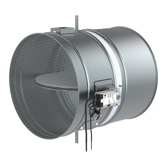
3/48 | FDR-3G…OF Overflow Fire Damper FDR-3G Description Overflow fire dampers up to size 630 mm represent passive fire protection, designed with the help of compartmentalization to prevent the spread of toxic gases, smoke and fire. Standard fire dampers are designed and certified in accordance with EN 15650 and tested for EIS criteria according to EN 1366–2. - Page 4 4/48 | FDR-3G…OF • Low pressure drop • Changeable mechanism • Inspection opening built-in • Great variety of installations rated up to EI120S Activation Types • H0-OF Overflow fire damper with an activation mechanism with a cover, manual crank and with a spring return release mechanism activated by a fusible thermal link set to 74°C (on demand 100°C).
- Page 5 5/48 | FDR-3G…OF • AM-FD: Activation Mechanisms • CBR-FD: Cover Boards...
-
Page 6: Technical Parameters
6/48 | FDR-3G…OF Technical Parameters Durability test 50 cycles/manually operated activation mechanism – with no change of the required properties 10000 + 100 + 100 cycles/actuator operated activation mechanism – with no change of the required properties Fire testing pressure Underpressure up to 300 Pa Safety position Closed. - Page 7 7/48 | FDR-3G…OF Blade tightness (STN EN 1751) Class 3 as standard Tightness of the housing (STN EN 1751) Class C as standard Conformity with EC directives 2006/42/EC Machinery Directive 2014/35/EU Low Voltage Directive 2014/30/EU Electromagnetic Compatibility Directive Driving actuator types Belimo: BLF230-T, BLF24-T, BF230-T, BF24-T, BFN230-T, BFN24-T, BFN24-T, BFL230-T, BFL24-T (also with connection possibilities with acronyms ST, W) Gruner: 360TA-230-12-S2, 360TA-024-12-S2, 340TA-230D-03-S2, 340TA-024D-03-S2, 340TA-230-05-S2,...
- Page 8 8/48 | FDR-3G…OF Legend P1 Blade P2 Casing P3 Manually operated activation mechanism (H0;H...) P4 Actuator operated activation mechanism (B...;G...) P5 Inspection lid P6 Thermoelectric fuse (BAT72;TA-72) P7 Supply and communication unit (BKN230-24;FS-UFC24-2) P8 Bendable hanger P9 Release and test button P10 Crank P11 Open position P12 Closed position...
- Page 9 9/48 | FDR-3G…OF P15 Grid P16 Extended ductwork...
- Page 10 10/48 | FDR-3G…OF Assessed Performance - FDR-3G 1396 Systemair Production a.s. Hlavná 371, 900 43 Kalinkovo, Slovakia 1396-CPR-0162, FDR-3G (valid for subgroups: …EX, …KS, …OF) EN 15650 : 2010 Circular fire dampers Nominal activation conditions/sensitivity - Pass sensing element load bearing capacity...
-
Page 11: Diagrams
11/48 | FDR-3G…OF Diagrams FDR-3G-200-H0-OF FDR-3G-225-H0-OF Pressure drop & sound power level (A-weighted) Pressure drop & sound power level (A-weighted) 50 dB(A) 50 dB(A) 45 dB(A) 45 dB(A) 40 dB(A) 40 dB(A) 35 dB(A) 35 dB(A) 30 dB(A) 30 dB(A) 25 dB(A) 25 dB(A) 1000... - Page 12 12/48 | FDR-3G…OF FDR-3G-315-H0-OF FDR-3G-400-H0-OF Pressure drop & sound power level (A-weighted) Pressure drop & sound power level (A-weighted) 1000 50 dB(A) 50 dB(A) 45 dB(A) 45 dB(A) 40 dB(A) 40 dB(A) 35 dB(A) 35 dB(A) 30 dB(A) 30 dB(A) 25 dB(A) 25 dB(A) 1000...
-
Page 13: Dimensions
13/48 | FDR-3G…OF Dimensions Free area Dimensions Note: 3) Inclusive bearing Overhangs Weights... -
Page 14: Ordering Code
14/48 | FDR-3G…OF Ordering Code DN - Nominal Dimension, øDN from 200 mm up to 630 mm B - Type of Activation (H0-OF up to GSD24T-OF) H0-OF (Manual crank, no switches) H2-OF (Manual crank, 2 switches 230V AC or 24V AC/DC) H5-2-OF (Manual crank, 24V AC/DC electromagnet, 2 switches 230V AC or 24V AC/DC) H6-2-OF (Manual crank, 230V AC electromagnet, 2 switches 230V AC or 24V AC/DC) B230T-OF (230V AC Belimo Actuator) - Page 15 15/48 | FDR-3G…OF ø 250 ≤ DN ≤ ø630 Standardardly in position: B; On demand in position: L, T.
-
Page 16: Installation
16/48 | FDR-3G…OF Installation Methods Notes: ve - Vertical (wall) ho - Horizontal (floor/ceiling) Installation, Maintenance & Operation Some damper parts may have sharp edges – therefore to protect yourself from harm, please use gloves during damper installation and manipulation. In order to prevent electric shock, fire or any other damage which could result from incorrect damper usage and operation, it is important to: ensure that installation is performed by a trained person. - Page 17 17/48 | FDR-3G…OF Installation rules • The damper must not support any part of the surrounding construction or wall which could cause damage and consequent damper failure. • The damper driving mechanism can be placed on either side of the wall, however it needs to be placed so as to ensure easy access during inspection.
- Page 18 18/48 | FDR-3G…OF Installation 1 - Wet Using Plaster/Mortar/Concrete Filling The supporting construction opening must be prepared as depicted. Opening surfaces must be even and cleaned off. The flexible wall opening must be reinforced as per the standards for plasterboard walls. The opening dimensions are driven by the nominal dimensions of the damper with added clearance.
- Page 19 19/48 | FDR-3G…OF...
- Page 20 20/48 | FDR-3G…OF...
- Page 21 21/48 | FDR-3G…OF Legend F1 Screw ≥ 5,5 DIN7981 or suitable wall plug and screw size 6. F2 Plaster/mortar/concrete filling 1 Fire damper (actuator side) 2 Bendable hanger 3 Concrete/masonry/cellular concrete wall or ceiling 4 Flexible (plasterboard) wall 4a 2 layers of plasterboard fireproof plate type F, EN 520 4b Vertical CW –...
- Page 22 22/48 | FDR-3G…OF Installation 2 - Dry Using Mineral Wool and Cover Boards The supporting construction opening must be prepared as depicted. Opening surfaces must be even and cleaned off. The flexible wall opening must be reinforced as per the standards for plasterboard walls. The opening dimensions are driven by the nominal dimensions of the damper with added clearance.
- Page 23 23/48 | FDR-3G…OF...
- Page 24 24/48 | FDR-3G…OF...
- Page 25 25/48 | FDR-3G…OF Legend F1 Screw ≥ 5,5 DIN7981 or suitable wall plug and screw size 6. F3 Mineral wool filling (min. 50 kg/m3) F4 Fire resistive coating, e.g. Promastop-CC/Promat A1 Cover board CBR-FD (accessory) obligatory 1 Fire damper (actuator side) 2 Bendable hanger 3 Concrete/masonry/cellular concrete wall or ceiling 4 Flexible (plasterboard) wall...
- Page 26 26/48 | FDR-3G…OF Installation 3 - Soft Installation into a Soft Crossing with fire-resistive coating The supporting construction opening must be prepared as depicted. Opening surfaces must be even and cleaned off. The flexible wall opening must be reinforced as per the standards for plasterboard walls. The opening dimensions are driven by the nominal dimensions of the damper with added clearance.
- Page 27 27/48 | FDR-3G…OF...
- Page 28 28/48 | FDR-3G…OF...
- Page 29 29/48 | FDR-3G…OF Legend F1 Screw ≥ 5,5 DIN7981 or suitable wall plug and screw size 6. F5 Mineral wool segment (minimum 150 kg/m3). F6 Layer of fire resistive coating (Promastop-CC/Promat) at least 2 mm thick for exposed surfaces. 1 Fire damper (actuator side) 2 Bendable hanger 3 Concrete/masonry/cellular concrete wall or ceiling 4 Flexible (plasterboard) wall...
- Page 30 30/48 | FDR-3G…OF Installation 3H - Hilti Filling made only from Hilti foam Tip: Excess material can be reused as the filling for this installation. It can be inserted into the cavity before you add new foam from the gun. The supporting construction opening must be prepared as depicted.
- Page 31 31/48 | FDR-3G…OF...
- Page 32 32/48 | FDR-3G…OF...
- Page 33 33/48 | FDR-3G…OF Legend F1 Screw ≥ 5,5 e.g. DIN7981 or suitable wall plug and screw size 6. F17 Foam CFS-F FX/HILTI. 1 Fire damper (actuator side) 2 Bendable hanger 3 Concrete/masonry/cellular concrete wall or ceiling 4 Flexible (plasterboard) wall 4a 2 layers of plasterboard fireproof plate type F, EN 520 4b Vertical CW –...
- Page 34 34/48 | FDR-3G…OF Electrical connections T/PC Activation Type / Power Consumption Type of activation H0-OF This type of activation mechanism does not have any electrical equipment.
-
Page 35: Electrical Parameters
35/48 | FDR-3G…OF Type of activation H2-OF IMPORTANT: Risk of electric shock! Switch off the power supply before working on any electrical equipment. Allow only qualified electricians to work on the electrical system. Microswitch:Power Supply: AC 125/250 V or DC 12/24 V Electric Parameters: 3A NOTES:•... - Page 36 36/48 | FDR-3G…OF Type of activation H5-2-OF IMPORTANT: Risk of electric shock! Switch off the power supply before working on any electrical equipment. Allow only qualified electricians to work on the electrical system. Microswitch: Power Supply: AC 125/250 V or DC 12/24 V Electric Parameters: 3A Impulse Electromagnet: Power Supply: AC (50/60 Hz)/DC 24 V...
- Page 37 37/48 | FDR-3G…OF Type of activation H6-2-OF IMPORTANT: Risk of electric shock! Switch off the power supply before working on any electrical equipment. Allow only qualified electricians to work on the electrical system. Microswitch: Power Supply: AC 125/250 V or DC 12/24 V Electric Parameters: 3A Impulse Electromagnet: Power Supply: AC 230 V, 50/60 Hz...
- Page 38 38/48 | FDR-3G…OF Type of activation B230T-OF IMPORTANT: Risk of electric shock! Switch off the power supply before working on any electrical equipment. Allow only qualified electricians to work on the electrical system. Actuator power supply: AC 230 V, 50/60 Hz NOTES: •...
- Page 39 39/48 | FDR-3G…OF Type of activation G230T-OF IMPORTANT: Risk of electric shock! Switch off the power supply before working on any electrical equipment. Allow only qualified electricians to work on the electrical system. Actuator power supply: AC 230 V, 50/60 Hz NOTES: •...
- Page 40 40/48 | FDR-3G…OF Type of activation B24T-OF IMPORTANT: Risk of electric shock! Switch off the power supply before working on any electrical equipment. Allow only qualified electricians to work on the electrical system. Actuator power supply: AC (50/60 Hz)/DC 24 V NOTES: •...
- Page 41 41/48 | FDR-3G…OF Type of activation G24T-OF IMPORTANT: Risk of electric shock! Switch off the power supply before working on any electrical equipment. Allow only qualified electricians to work on the electrical system. Actuator power supply: AC (50/60 Hz)/DC 24 V NOTES: •...
- Page 42 42/48 | FDR-3G…OF Type of activation BSD230T-OF IMPORTANT: Risk of electric shock! Switch off the power supply before working on any electrical equipment. Only qualified electricians are allowed to work on the electrical system. Power consumption must be observed. NOTES: •...
- Page 43 43/48 | FDR-3G…OF Type of activation GSD230T-OF IMPORTANT: Risk of electric shock! Switch off the power supply before working on any electrical equipment. Only qualified electricians are allowed to work on the electrical system. Power consumption must be observed. NOTES: •...
- Page 44 44/48 | FDR-3G…OF Type of activation BSD24T-OF IMPORTANT: Risk of electric shock! Switch off the power supply before working on any electrical equipment. Allow only qualified electricians to work on the electrical system. Power consumption must be observed. NOTES: • Supply via safety isolation transformer. Legend 1 Blue cable colour 2 Brown cable colour...
- Page 45 45/48 | FDR-3G…OF Type of activation GSD24T-OF IMPORTANT: Risk of electric shock! Switch off the power supply before working on any electrical equipment. Allow only qualified electricians to work on the electrical system. Power consumption must be observed. NOTES: • Supply via safety isolation transformer. Legend 1 Blue cable colour 2 Brown cable colour...
-
Page 46: Operation Manual
46/48 | FDR-3G…OF Operation manual Warning To avoid injury, make sure to wear gloves and keep the blades movement area clear while manipulating with the damper. Fire Damper Functionality Check Manually Operated Activation Mechanism Open the damper - turn the red crank (P10) using a hexagon bent wrench No. 10 (P13). Turn the red crank so that the indicator arrow is pointing to the “OPEN“... - Page 47 47/48 | FDR-3G…OF The operator performs regular checks of the dampers as per established regulations and standards at least once every 12 months. The check needs to be performed by an employee who has been specifically trained for this purpose. The current fire damper condition determined during the inspection needs to be entered into the operating logbook along with the date of the inspection, the legible name, surname and signature of the employee who performed the inspection.
- Page 48 Systemair DESIGN • 2020-10-23 • HandBook_FDR_3G_OF_en-GB • 8519DCD0-0720-11EB-DCA1-21ABDD8D93BC...
Need help?
Do you have a question about the FDR-3G OF Series and is the answer not in the manual?
Questions and answers