Advertisement
Quick Links
Advertisement

Related Manuals for SystemAir FDS-3G EX Series


Summary of Contents for SystemAir FDS-3G EX Series
- Page 1 FDS...EX Atex Fire Damper...
-
Page 2: Table Of Contents
2/70 | FDS...EX Table of Contents Overview ............3 Technical Parameters . -
Page 3: Overview
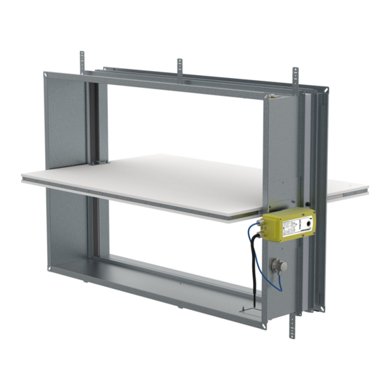
3/70 | FDS...EX Rectangular Fire Damper FDS-3G Description Atex fire dampers represent passive fire protection, designed with the help of compartmentalization to prevent the spread of toxic gases, smoke and fire. Standard fire dampers are designed and certified in accordance with EN 15650 and tested for EIS criteria according to EN 1366–2. - Page 4 4/70 | FDS...EX • Two inspection openings for all sizes greater than 200x200 mm • Great variety of installations rated up to EI120S • Multiple FDS-EI90S damper installation - up to 4 dampers with a maximum size of 3260 × 2060 mm Product Types •...
- Page 5 5/70 | FDS...EX Material Composition The product contains galvanized sheet metal, calcium silicate board, fireproof carbon fiberglass, polyurethane foam and ethylene-propylene rubber. These are processed in accordance with local regulations. The product contains no hazardous substances, except for the solder in the thermofuse, which contains a milligram of lead. List of Accessories Detailed information about accessories for FDS-3G...EX, FDS-EI90S...EX and FDS-EI120S...EX is available in SystemairDESIGN under Fire Damper Accessories.
-
Page 6: Technical Parameters
6/70 | FDS...EX Technical Parameters CE certificate number: FDS-3G...EX: 1396 - CPR - 0163 FDS-EI90S...EX, FDS-EI120S: 1396 - CPR - 0169 Atex certificate number: FDS-3G...EX: FTZÚ 20 ATEX 0017X FDS-EI90S...EX, FDS-EI120S: FTZÚ 20 ATEX 0016X Explosion Proof Class: {EX} II 2 D Ex h IIIB T85°C...T100°C Db, {EX} II 2 G Ex h IIB T6...T5 Gb. For activation type H2-EX the temperature class is reduced to T85°C Db and T6 Gb Durability test •... - Page 7 7/70 | FDS...EX Maintenance Not required. Dry cleaning if demanded by law in the country in which the dampers are installed. Revisions Determined by law in the country in which the fire dampers are installed but at least every 12 months. Allowed pressure 1200 Pa Blade tightness (STN EN 1751)
- Page 8 8/70 | FDS...EX Product parts...
- Page 9 9/70 | FDS...EX Legend P1 Blade P2 Casing P3 Manually operated activation mechanism (H0-EX;H2-EX) P4 Actuator operated activation mechanism (SET-EX;SRT-EX) P5 Inspection lid P6 Thermoelectric fuse (ExPro-TT-72,Schischek) P8 Bendable hanger P9 Release and test button P10 Crank P11 Open position P12 Closed position P13 Hexagonal bent wrench No.10 (not part of delivery)
- Page 10 10/70 | FDS...EX Assessed Performance - FDS-3G Assessed Performance - FDS-EI90S, FDS-EI120S 1396 1396 Systemair Production a.s. Systemair Production a.s. Hlavná 371, 900 43 Kalinkovo, Slovakia Hlavná 371, 900 43 Kalinkovo, Slovakia 1396-CPR-0163, FDS-3G 1396-CPR-0169, FDS-EI90S, FDS-EI120S (valid for subgroups: …EX, …KS, …OF) (valid for subgroups: …EX)
-
Page 11: Diagrams
11/70 | FDS...EX Diagrams FDS-3G-...-H0-EX FDS-3G-...-H0-EX Pressure drop & sound power level (A-weighted) Pressure drop & sound power level (A-weighted) 1000 50 dB(A) Width: 300, Height: 200 Width: 300, Height: 400 Width: 300, Height: 500 Width: 300, Height: 100 50 dB(A) 55 dB(A) 50 dB(A) 50 dB(A) - Page 12 12/70 | FDS...EX FDS-3G-...-H0-EX FDS-3G-...-H0-EX Pressure drop & sound power level (A-weighted) Pressure drop & sound power level (A-weighted) 1000 2000 3000 2000 3000 5000 50 dB(A) 55 dB(A) Width: 900, Height: 500 Width: 900, Height: 600 Width: 900, Height: 200 Width: 900, Height: 300 50 dB(A) 45 dB(A) 50 dB(A)
- Page 13 13/70 | FDS...EX FDS-EI90S-...-H0-EX FDS-EI90S-...-H0-EX Pressure drop & sound power level (A-weighted) Pressure drop & sound power level (A-weighted) 5000 8000 10000 8000 10000 Width: 900, Height: 950 Width: 1200, Height: 900 Width: 900, Height: 1000 50 dB(A) 50 dB(A) Width: 1200, Height: 950 50 dB(A) Width: 1200, Height: 850...
- Page 14 14/70 | FDS...EX Free area W (mm) 100 150 200 250 300 315 350 355 400 450 500 550 560 600 630 650 700 710 750 800 0,007 0,010 0,014 0,018 0,022 0,023 0,026 0,026 0,030 0,030 0,034 0,037 0,038 0,041 0,043 0,044 0,048 0,049 0,051 0,055 0,011 0,015 0,021 0,027 0,033 0,034 0,038 0,039 0,044 0,047 0,052 0,058 0,059 0,063 0,066 0,068 0,074 0,075 0,079 0,085 0,013 0,019 0,026 0,033 0,040 0,042 0,047 0,048 0,054 0,058 0,064 0,071 0,072 0,078 0,082 0,084 0,091 0,092 0,098 0,104 0,014 0,019 0,027 0,034 0,041 0,043 0,048 0,049 0,056 0,060 0,067 0,074 0,075 0,081 0,085 0,087 0,094 0,096 0,101 0,108...
- Page 15 15/70 | FDS...EX W (mm) 950 1000 1050 1100 1120 1150 1200 1250 1300 1350 1400 1450 1500 1550 1600 0,193 0,201 0,209 0,217 0,224 0,232 0,105 0,111 0,118 0,124 0,131 0,137 0,140 0,144 0,150 0,183 0,19 0,198 0,205 0,212 0,22 0,256 0,266 0,276 0,286 0,297 0,307 0,145 0,154 0,163 0,172 0,181 0,190 0,194 0,199 0,208...
-
Page 16: Dimensions
16/70 | FDS...EX Dimensions Dimensions To avoid blocking the movement of a damper blade, connect a straight duct at minimal lengths respectively R1 or R2. R1 and R2 are the overhang of the fully open blade, including seals and gaskets on the damper blade. NOTES '* For a nominal size W = 100 mm, the internal width dimension is 100 mm, the flange outside width dimension 152 mm, and/or for a nominal size H = 100 mm the internal height dimension is 100 mm, flange outside height dimension... - Page 17 17/70 | FDS...EX FDS-EI90S...EX and FDS-EI120S...EX, up to 1600 x 1000 Overhangs H (mm) 100 150 175 180 200 250 300 315 350 355 400 450 500 550 560 600 630 650 700 710 750 800 -188 -163 -150 -148 -143 -118 -93 107 112 132 157 EI90S/EI120S -160 -145 -110 -102 -85...
- Page 18 18/70 | FDS...EX Weights W (mm) (kg ± 5%) 100 150 200 250 300 315 350 355 400 450 500 550 560 600 630 650 700 710 750 800 10,1 10,6 10,0 10,4 10,9 11,3 11,8 11,9 12,3 12,5 12,7 13,2 13,3 13,6 14,1 10,2 10,4 10,9 11,0 11,4 11,9 10,2 10,3 10,7 10,8 11,2 11,8 12,3 12,8 12,9 13,4 13,7 13,9 14,4 14,5 14,9 15,4 10,4 10,5 11,0 11,3 11,6 12,2 12,3 12,7 13,3...
- Page 19 19/70 | FDS...EX W (mm) (kg ± 5%) 850 900 950 1000 1050 1100 1120 1150 1200 1250 1300 1350 1400 1450 1500 1550 1600 21,2 24,5 26,1 28,0 29,8 31,7 33,5 33,5 34,8 34,9 35,5 36,2 36,9 37,6 38,3 24,7 28,0 29,6 31,5 33,3 35,2 37,0 37,0 38,3 38,4 39,0 39,7 40,4 41,1 41,8 24,0 26,2 27,3 29,2 31,1 33,0 34,9 34,9 35,6 35,6 36,3 37,0 37,7 38,4 39,1...
-
Page 20: Ordering Code
20/70 | FDS...EX Ordering Code A - Damper type EI90S EI120S W - Width Dimension from 100 mm up to 1200 mm (FDS-3G) from 450 mm up to 1600 mm (FDS-EI90S, FDS-EI120S) H - Height Dimension from 100 mm up to 800 mm (FDS-3G) from 200 mm up to 1000 mm (FDS-EI90S, FDS-EI120S) B - Type of Activation (H0-EX up to SRT-EX) H0-EX (Manual crank, no switches) - Page 21 21/70 | FDS...EX Positions of inspection opening (Removable mechanism is available for all sizes) W and H < 200 No opening for inspection. Inspection possible through removable mechanism or additional inspection opening must be added to the connecting duct. W and H ≥ 200 Standardly in position: BR and TR;...
-
Page 22: Installation
22/70 | FDS...EX Installation Methods EI 60 (v i ↔ o) S FDS-3G...EX EI 90 (v i ↔ o) S 100 × 100 ..1200 × 800 360° 1 Wet EI 120 (v i ↔ o) S EI 60 (v i ↔... - Page 23 23/70 | FDS...EX FDS-EI90S...EX EI 90 (v i ↔ o) S W ≤ 1600 & H ≤ 1000 FDS-EI120S...EX 1 Wet EI 120 (v i ↔ o) S W ≤ 1600 & H ≤ 1000 ≤ 1000 × 1000 FDS-EI90S...EX EI 90 (v i ↔...
- Page 24 24/70 | FDS...EX Rectangular fire dampers are certified according to EN 15650, tested according to EN 1366-2, classified according to EN13501-3 and explosion-proof certified according to Directive 2014/34/EU and EN ISO 80079-36.2016 - reached classes are: II 2 D Ex h IIIB T85°C...T100°C Db, II 2 G Ex h IIB T6...T5 Gb. For activation type H2-EX the temperature class is reduced to T85°C Db and T6 Gb.
- Page 25 25/70 | FDS...EX Installation 1 - Wet Using Plaster/Mortar/Concrete Filling Important: Use support inside the damper when adding filling. The weight of the filling can damage or bend the damper casing. 1. The supporting construction opening must be prepared as depicted. Opening surfaces must be even and cleaned off.
- Page 26 26/70 | FDS...EX FDS-EI90S...EX EI 90 (v i ↔ o) S W ≤ 1600 & H ≤ 1000 FDS-EI120S...EX 1 Wet EI 120 (v i ↔ o) S W ≤ 1600 & H ≤ 1000 ≤ 1000 × 1000...
- Page 27 27/70 | FDS...EX...
- Page 28 28/70 | FDS...EX Legend F1 Screw ≥ 5,5 DIN7981 or suitable wall plug and screw size 6. F2 Plaster/mortar/concrete filling 1 Fire damper (actuator side) 2 Bendable hanger 3 Concrete/masonry/cellular concrete wall or ceiling 4 Flexible (plasterboard) wall 4a 2 layers of plasterboard fireproof plate type F, EN 520 4b Vertical CW –...
- Page 29 29/70 | FDS...EX Installation 2 - Dry Using Mineral Wool and Cover Boards 1. The supporting construction opening must be prepared as depicted. Opening surfaces must be even and cleaned off. The flexible wall opening must be reinforced as per the standards for plasterboard walls. The opening dimensions are driven by the nominal dimensions of the damper with added clearance.
- Page 30 30/70 | FDS...EX...
- Page 31 31/70 | FDS...EX...
- Page 32 32/70 | FDS...EX Legend F1 Screw ≥ 5,5 DIN7981 or suitable wall plug and screw size 6. F3 Mineral wool filling (min. 50 kg/m3) F4 Fire resistive coating, e.g. Promastop-CC/Promat A1 Cover board CBS-FD (accessory) obligatory 1 Fire damper (actuator side) 2 Bendable hanger 3 Concrete/masonry/cellular concrete wall or ceiling 4 Flexible (plasterboard) wall...
- Page 33 33/70 | FDS...EX Installation 3 - Soft Installation into a Soft Crossing with fire-resistive coating With this installation, we recommend using flexible connections (see accessory FCR) due to thermal expansion of connected ducts during fire. Install the compensator so that the flexible part has a minimum distance of 50 mm from the edge of a damper‘s blade in an open position.
- Page 34 34/70 | FDS...EX EI 60 (v i ↔ o) S EI 90 (v i ↔ o) S FDS-3G...EX 100 × 100 ... EI 60 (h i ↔ o) S ... 1200 × 800 360° 3 Soft EI 90 (h i ↔ o) S EI 120 (h i ↔...
- Page 35 35/70 | FDS...EX...
- Page 36 36/70 | FDS...EX...
- Page 37 37/70 | FDS...EX Legend F1 Screw ≥ 5,5 DIN7981 or suitable wall plug and screw size 6. F5 Mineral wool segment (minimum 150 kg/m3). F6 Layer of fire resistive coating (Promastop-CC/Promat) at least 2 mm thick for exposed surfaces. F7 L-profile 60 × 40 × 3 mm, length W + 300 mm or WL + 300 mm F8 Screw 3,9 ×...
- Page 38 38/70 | FDS...EX Installation 3H - Hilti Filling made only from Hilti foam With this installation, we recommend using flexible connections (see accessory FCR) due to thermal expansion of connected ducts during fire. Install the compensator so, that the flexible part has a minimum distance of 50 mm from the edge of a damper‘s blade in the open position.
- Page 39 39/70 | FDS...EX...
- Page 40 40/70 | FDS...EX...
- Page 41 41/70 | FDS...EX Legend F1 Screw ≥ 5,5 e.g. DIN7981 or suitable wall plug and screw size 6. F17 Foam CFS-F FX/HILTI. 1 Fire damper (actuator side) 2 Bendable hanger 3 Concrete/masonry/cellular concrete wall or ceiling 4 Flexible (plasterboard) wall 4a 2 layers of plasterboard fireproof plate type F, EN 520 4b Vertical CW –...
- Page 42 42/70 | FDS...EX Installation, 5.1 - ON & OUT of the wall EI90S Using 2 layers of Mineral Wool TIP: The duct-wall cavity filling can be also replaced by plaster/mortar/concrete (F2) as a replacement of filling (F9), then the coating (F10) is not needed for the cavity filling. 1.
- Page 43 43/70 | FDS...EX FDS-EI90S...EX EI 90 (v - i ↔ o) S W ≤ 1600 & H ≤ 1000 On, Out...
- Page 44 44/70 | FDS...EX...
- Page 45 45/70 | FDS...EX Legend F1 Screw ≥ 5,5 DIN7981 or suitable wall plug and screw size 6. F7 L-profile 60 × 40 × 3 mm, length W + 300 mm or WL + 300 mm F8 Screw 3,9 × max. 13 DIN7504 F9 Mineral wool segment (min.
- Page 46 46/70 | FDS...EX Notes a) - Flexible (plasterboard) wall b) - Concrete/masonry/cellular concrete (rigid) wall - Vertical wall Rules for hanger placements and duct suspensions depend on the dampers distance from the supporting construction The distance P is the distance from the blade axis to the damper flange. The distance depends on the type of damper used.
- Page 47 47/70 | FDS...EX Installation, 5.2 - ON & OUT of the wall EI60S Using 1 layer of Mineral Wool TIP: The duct-wall cavity filling can be also replaced by plaster/mortar/concrete (F2) as a replacement of filling (F9), then the coating (F10) is not needed for the cavity filling. Damper Preparation before Installation: Fasten the rectangular damper in the blade/perforation location only on the top and bottom sides with U-profiles (28), and then fasten the U-profiles together by using the threaded rod M10 (20).
- Page 48 48/70 | FDS...EX...
- Page 49 49/70 | FDS...EX...
- Page 50 50/70 | FDS...EX Legend F9 Mineral wool segment (min. 66 kg/m3) - in a wall F10 Layer of fire resistive coating (BSF/ISOVER) at least 2 mm thick for exposed surfaces 1 Fire damper (actuator side) 3 Concrete/masonry/brick/cellular concrete wall or ceiling 4 Flexible (plasterboard) wall 4a 2 layers of plasterboard fireproof plate type F, EN 520 4b Vertical CW –...
- Page 51 51/70 | FDS...EX Installation, maximum, 5.3 - ON & OUT of the wall EI90S Using Promatect Boards TIP: The duct-wall cavity filling (F12) and its coating (F13) can be also replaced by plaster/mortar/concrete (F2). Damper Preparation before Installation: Attach all 4 parts of the IKOWS-FD accessory around the casing where the damper blade is situated, as shown in the picture and apply a suitable fire-resistive coating (F13) to the contact surfaces of the boards and the damper.
- Page 52 52/70 | FDS...EX...
- Page 53 53/70 | FDS...EX...
- Page 54 54/70 | FDS...EX Legend F1 Screw ≥ 5,5 DIN7981 or suitable wall plug and screw size 6. F12 Mineral wool segment thickness of 50 mm; min. 150 kg/m3 - in a wall F13 Fire resistive coating; Promat kleber K84/Promat F14 Steel L-profile 25 × 25 × 2 mm F15 Gypsum board thickness of 15 mm;...
- Page 55 55/70 | FDS...EX A4 Installation kit IKOWS-FD-W×H (accessory) 1 Fire damper (actuator side) 3 Concrete/masonry/brick/cellular concrete wall or ceiling 4 Flexible (plasterboard) wall 4a 2 layers of plasterboard fireproof plate type F, EN 520 4b Vertical CW – profiles 4c Horizontal CW – profiles 4d Mineral wool;...
- Page 56 56/70 | FDS...EX Installation, 5.4 - ON & OUT of the wall, EI60S Using Promatect Boards TIP: The duct-wall cavity filling (F12) and its coating (F13) can be also replaced by plaster/mortar/concrete (F2). Damper Preparation before Installation: Attach all 4 parts of the IKOWS-FD accessory around the casing where the damper blade is situated, as shown in the picture and apply a suitable fire resistive coating (F13) to the contact surfaces of the boards and the damper.
- Page 57 57/70 | FDS...EX FDS-3G...EX EI 60 (v - i ↔ o) S 100 × 100 ..1200 × 800 On, Out...
- Page 58 58/70 | FDS...EX...
- Page 59 59/70 | FDS...EX...
- Page 60 60/70 | FDS...EX Legend F1 Screw ≥ 5,5 DIN7981 or suitable wall plug and screw size 6. F12 Mineral wool segment thickness of 50 mm; min. 150 kg/m3 - in a wall F13 Fire resistive coating; Promat kleber K84/Promat F14 Steel L-profile 25 × 25 × 2 mm F15 Gypsum board thickness of 15 mm;...
- Page 61 61/70 | FDS...EX Notes a) - Flexible (plasterboard) wall b) - Concrete/masonry/cellular concrete (rigid) wall - Vertical wall Rules for hanger placements and duct suspensions depend on the dampers distance from the supporting construction Rules for hanger placements LP and duct suspensions LS depend on the damper’s distance from the supporting construction LE The distance P is the distance from the blade axis to the damper flange.
- Page 62 62/70 | FDS...EX 7 Multiple Damper Installation, EI90S Installing a Set of FDS-EI90S Fire Dampers 1. For a damper installation, prepare a square opening with the dimensions W1 and H1, the opening surfaces must be even and cleaned off. 2. Determine the bottom level of the duct body crossing and insert L-profiles (F7) on both wall sides. While fixing with screws (F8), perform a level check.
- Page 63 63/70 | FDS...EX FDS-EI90S...EX EI 90 (v - i ↔ o) S W ≤ 1600 & H ≤ 1000 7 Multi...
- Page 64 64/70 | FDS...EX Legend F1 Screw ≥ 5,5 DIN7981 or suitable wall plug and screw size 6. F4 Fire resistive coating, e.g. Promastop-CC/Promat F5 Mineral wool segment (min. 150 kg/m3) F7 L-profile 60 × 40 × 3 mm, length W + 300 mm or WL + 300 mm F8 Screw 3,9 ×...
-
Page 65: Electrical Parameters
65/70 | FDS...EX Electrical connections Type of activation H0-EX IMPORTANT: Fire damper must be grounded. Wires connecting damper parts, must not be removed This type of activation mechanism does not have any electrical equipment. Type of activation H2-EX IMPORTANT: Risk of electric shock! Each explosion-proof electrical equipment installed in or on the fire damper must conform to its explosion-proof given explosive atmospheres according to EN 60079-10. - Page 66 66/70 | FDS...EX Type of activation SET-EX IMPORTANT: Risk of electric shock! Each explosion-proof electrical equipment installed in or on the fire damper must conform to its explosion-proof given explosive atmospheres according to EN 60079-10. Fire damper must be grounded. Wires connecting damper parts must not be removed Switch off the power supply before working on any electrical equipment.
- Page 67 67/70 | FDS...EX Type of activation SRT-EX IMPORTANT: Risk of electric shock! Each explosion-proof electrical equipment installed in or on the fire damper must conform to its explosion-proof given explosive atmospheres according to EN 60079-10. Fire damper must be grounded. Wires connecting damper parts must not be removed Switch off the power supply before working on any electrical equipment.
-
Page 68: Operation Manual
68/70 | FDS...EX Operation manual Warning To avoid injury, make sure to wear gloves and keep the blades movement area clear while manipulating the damper. Fire Damper Functionality Check Manually Operated Activation Mechanism 1. Open the damper - turn the red crank (P10) using a bent Allen wrench No. 10 (P13). Turn the red crank so that the indicator arrow is pointing to the “OPEN“... - Page 69 69/70 | FDS...EX Damper Inspection The activation mechanism keeps the dampers on stand-by during their entire life cycle in accordance with this manual issued by the manufacturer. It is not permitted to alter the dampers in any way nor to perform any changes to their structure without the manufacturer’s consent.
- Page 70 Systemair DESIGN • 2021-04-27 • Handbook_FDS_EX_en-GB...
Need help?
Do you have a question about the FDS-3G EX Series and is the answer not in the manual?
Questions and answers