Advertisement
Quick Links
Advertisement

Subscribe to Our Youtube Channel
Related Manuals for SystemAir FDR-3G EX Series


Summary of Contents for SystemAir FDR-3G EX Series
- Page 1 FDR-3G…EX Atex Fire Damper FDR-3G Handbook...
-
Page 2: Table Of Contents
2/50 | FDR-3G…EX Table of Contents Overview ............3 Technical Parameters . -
Page 3: Overview
3/50 | FDR-3G…EX Description Atex fire dampers represent passive fire protection, designed with the help of compartmentalization to prevent the spread of toxic gases, smoke and fire. Standard fire dampers are designed and certified in accordance with EN 15650 and tested for EIS criteria according to EN 1366–2. Fire dampers together with their installation form an inseparable part of a fire resistivity rating. - Page 4 4/50 | FDR-3G…EX • Inspection opening built-in • Great variety of installations rated up to EI120S Activation Types Manually Operated Fire Dampers By default, all manually operated fire dampers are supplied with a hand crank, optionally with microswitches. In case of fire, the fire damper is closes automatically after the melting of the thermal fuse.
- Page 5 5/50 | FDR-3G…EX • AM-FD: Activation Mechanisms • CBR-FD: Cover Boards • IPOR-FD: Insulation Cover Plates Specific Conditions of Use: • The fire damper is suitable for the use with the ambient temperature Ta = 0°C/+60°C. In case of additional electrical equipment (limit switch, temperature sensor, servo-drive) the temperature range is reduced according to the range of the used device.
-
Page 6: Technical Parameters
6/50 | FDR-3G…EX Technical Parameters CE certificate number 1396 - CPR - 0162 ATEX certificate number FTZÚ 20 ATEX 0035X Explosion Proof Class {EX} II 2 D Ex h IIIB T85°C...T100°C Db, {EX} II 2 G Ex h IIB T6...T5 Gb. For activation type H2-EX the temperature class is reduced to T85°C Db and T6 Gb Durability test •... - Page 7 7/50 | FDR-3G…EX Blade tightness (STN EN 1751) Class 3 as standard Tightness of the housing (STN EN 1751) Class C as standard Conformity with EC directives 2006/42/EC Machinery Directive 2014/35/EU Low Voltage Directive 2014/30/EU Electromagnetic Compatibility Directive Driving actuator types Schisckek ExMax Schisckek RedMax Transport and Storage...
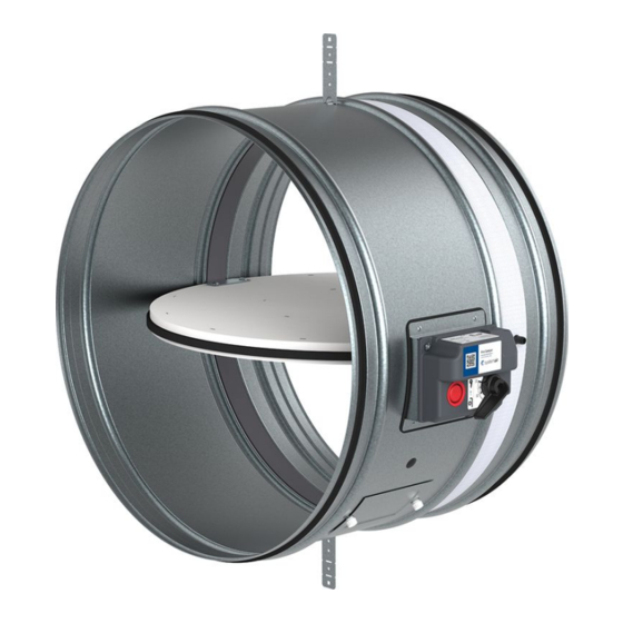
- Page 8 8/50 | FDR-3G…EX Product parts FDR-3G...EX FDR-3G...EX DN≤630 DN>630 P1 P2 P8 P5 P4 P14 P1 P2 P4 P14...
- Page 9 9/50 | FDR-3G…EX Legend P1 Blade P2 Casing P3 Manually operated activation mechanism (H0-EX; H2-EX) P4 Actuator operated activation mechanism (SET-EX; SRT-EX) P5 Inspection lid P6 Thermoelectric fuse (ExPro-TT-72, Schischek) P8 Bendable hanger P9 Release and test button P10 Crank P11 Open position P12 Closed position P13 Hexagon bent wrench No.10 (not part of delivery)
- Page 10 10/50 | FDR-3G…EX Assessed Performance - FDR-3G 19 CE 1396 Systemair Production a.s. Hlavná 371, 900 43 Kalinkovo, Slovakia 1396-CPR-0162, FDR-3G (valid for subgroups: …EX, …KS, …OF) EN 15650 : 2010 Circular fire dampers Nominal activation conditions/sensitivity - Pass • sensing element load bearing capacity •...
-
Page 11: Diagrams
11/50 | FDR-3G…EX Diagrams The pressure drop and A-weighted total discharged sound power level depend on the nominal diameter of the damper and air flow volume at different duct pressures. The type of activation does not influences the airflow parameter, therefore only one activation type is shown in the diagrams. - Page 12 12/50 | FDR-3G…EX FDR-3G-...-H0-EX FDR-3G-...-H0-EX Pressure drop & A-weighted sound power level in dB(A) Pressure drop & A-weighted sound power level in dB(A) 1000 1000 2000 Size: 560 Size: 400 Size: 450 Size: 630 Size: 710 Size: 500 2000 3000 5000 m³/h 3000...
-
Page 13: Dimensions & Weights
13/50 | FDR-3G…EX Dimensions DN 100 up to DN 630 Free area DN (mm) 100 125 140 150 160 180 200 225 250 280 315 355 400 450 500 560 630 0,003 0,007 0,009 0,011 0,013 0,018 0,023 0,031 0,039 0,050 0,065 0,085 0,110 0,138 0,173 0,220 0,283 Dimensions FDR-3G...EX DN≤630... - Page 14 14/50 | FDR-3G…EX DN 710 up to DN 1000 Free area DN (mm) 1000 0,357 0,459 0,587 0,731 Dimensions FDR-3G...EX DN>630 ≤185 (SET-B-EX; SRT-B-EX) ≤130 (SET-EX; SRT-EX) ≤85 (H0-EX; H2-EX) DN+30 (mm) Note: 3) Inclusive bearing Overhangs DN (mm) 1000 (mm) (mm) Weights...
-
Page 15: Ordering Code
15/50 | FDR-3G…EX Ordering Code DN - Dimension, øDN 100 mm up to 1000 mm B - Type of Activation (H0-EX up to SRT-EX) H0-EX (Manual crank, no switches) H2-EX (Manual crank, 2 switches 230V AC or 24V AC/DC) SET-EX (24...240 V AC/DC, Schischek ExMax) SRT-EX (24...240 V AC/DC, Schischek RedMax) SET-B-EX (24...240 V AC/DC, Schischek ExMax + ExBox-BF) SRT-B-EX (24...240 V AC/DC, Schischek RedMax + ExBox-BF) -
Page 16: Installation
16/50 | FDR-3G…EX Installation Methods EI 60 (v i ↔ o) S FDR-3G...EX EI 90 (v i ↔ o) S DN100 ... DN1000 360° 1 Wet EI 120 (v i ↔ o) S EI 60 (v i ↔ o) S FDR-3G...EX DN100 ... - Page 17 17/50 | FDR-3G…EX a) - Flexible (plasterboard) wall b) - Concrete/masonry/cellular concrete (rigid) wall c) - Concrete/cellular concrete (rigid) floor/ceiling - Vertical wall - Horizontal floor/ceiling Circular fire dampers are certified according to EN 15650, tested according to EN 1366-2, classified according to EN13501 and explosion-proof certified according to Directive 2014/34/EU and EN ISO 80079-36.2016, part 1 - the reached classes are: II 2 D Ex h IIIB T85°C...T100°C Db, II 2 G Ex h IIB T6...T5 Gb.
- Page 18 18/50 | FDR-3G…EX Installation 1 - Wet Using Plaster/Mortar/Concrete Filling 1. The supporting construction opening must be prepared as depicted. Opening surfaces must be even and cleaned off. The flexible wall opening must be reinforced as per the standards for plasterboard walls. The opening dimensions are driven by the nominal dimensions of the damper with added clearance.
- Page 19 19/50 | FDR-3G…EX...
- Page 20 20/50 | FDR-3G…EX...
- Page 21 21/50 | FDR-3G…EX Legend F1 Screw ≥ 5,5 DIN7981 or suitable wall plug and screw size 6. F2 Plaster/mortar/concrete filling 1 Fire damper (actuator side) 2 Bendable hanger 3 Concrete/masonry/cellular concrete wall or ceiling 4 Flexible (plasterboard) wall 4a 2 layers of plasterboard fireproof plate type F, EN 520 4b Vertical CW –...
- Page 22 22/50 | FDR-3G…EX Installation 2 - Dry Using Mineral Wool and Cover Boards 1. The supporting construction opening must be prepared as depicted. Opening surfaces must be even and cleaned off. The flexible wall opening must be reinforced as per the standards for plasterboard walls. The opening dimensions are driven by the nominal dimensions of the damper with added clearance.
- Page 23 23/50 | FDR-3G…EX...
- Page 24 24/50 | FDR-3G…EX...
- Page 25 25/50 | FDR-3G…EX Legend F1 Screw ≥ 5,5 DIN7981 or suitable wall plug and screw size 6. F3 Mineral wool filling (min. 50 kg/m3) F4 Fire resistive coating, e.g. Promastop-CC/Promat A1 Cover board CBR-FD (accessory) obligatory 1 Fire damper (actuator side) 2 Bendable hanger 3 Concrete/masonry/cellular concrete wall or ceiling 4 Flexible (plasterboard) wall...
- Page 26 26/50 | FDR-3G…EX Installation 3 - Soft Installation into a Soft Crossing with fire resistive coating With this installation we recomend using a flexible connection (see accessory FCR) due to thermal expansion of connected ducts during fire. Install the compensator so, that the flexible part has a minimum distance of 50 mm from the edge of a damper‘s blade in open position.
- Page 27 27/50 | FDR-3G…EX...
- Page 28 28/50 | FDR-3G…EX...
- Page 29 29/50 | FDR-3G…EX Legend F1 Screw ≥ 5,5 DIN7981 or suitable wall plug and screw size 6. F5 Mineral wool segment (minimum 150 kg/m3). F6 Layer of fire resistive coating (Promastop-CC/Promat) at least 2 mm thick for exposed surfaces. 1 Fire damper (actuator side) 2 Bendable hanger 3 Concrete/masonry/cellular concrete wall or ceiling 4 Flexible (plasterboard) wall...
- Page 30 30/50 | FDR-3G…EX Installation 3H - Hilti Filling made only from Hilti foam With this installation we recommend using a flexible connection (see accessory FCR) due thermal expansion of connected ducts during fire. Install the compensator such that the flexible part has a minimum distance of 50 mm from the edge of a damper‘s blade in the open position.
- Page 31 31/50 | FDR-3G…EX...
- Page 32 32/50 | FDR-3G…EX...
- Page 33 33/50 | FDR-3G…EX Legend F1 Screw ≥ 5,5 e.g. DIN7981 or suitable wall plug and screw size 6. F17 Foam CFS-F FX/HILTI. 1 Fire damper (actuator side) 2 Bendable hanger 3 Concrete/masonry/cellular concrete wall or ceiling 4 Flexible (plasterboard) wall 4a 2 layers of plasterboard fireproof plate type F, EN 520 4b Vertical CW –...
- Page 34 34/50 | FDR-3G…EX Installation 5.1 - ON & OUT of the wall EI90S Using 2 layers of Mineral Wool TIP: The duct-wall cavity filling can be also replaced by plaster/mortar/concrete (F2) as a replacement of filling (F9), then the coating (F10) is not needed for the cavity filling. There are two hanging possibilities, using ringlet MP-MX or using ringlet UVH30 see instructions point 3.
- Page 35 35/50 | FDR-3G…EX...
- Page 36 36/50 | FDR-3G…EX...
- Page 37 37/50 | FDR-3G…EX Legend F9 Mineral wool segment (min. 66 kg/m3) - in a wall F10 Layer of fire resistive coating (BSF/ISOVER) at least 2 mm thick for exposed surfaces F11 Sheet metal belt 40 × 2 mm bent into an L shape of 35 and 160 mm A2 Insulation front cover IPOR-FD-DN (accessory) 1 Fire damper (actuator side) 3 Concrete/masonry/brick/cellular concrete wall or ceiling...
- Page 38 38/50 | FDR-3G…EX Installation 5.2 - ON & OUT of the wall, EI60S Using 1 layer of Mineral Wool TIP: The duct-wall cavity filling can be also replaced by plaster/mortar/concrete (F2) as a replacement of filling (F9), then the coating (F10) is not needed for the cavity filling. There are two hanging possibilities, using ringlet MP-MX or using ringlet UVH30 see instructions point 3.
- Page 39 39/50 | FDR-3G…EX...
- Page 40 40/50 | FDR-3G…EX...
- Page 41 41/50 | FDR-3G…EX Legend F9 Mineral wool segment (min. 66 kg/m3) - in a wall F10 Layer of fire resistive coating (BSF/ISOVER) at least 2 mm thick for exposed surfaces 1 Fire damper (actuator side) 3 Concrete/masonry/brick/cellular concrete wall or ceiling 4 Flexible (plasterboard) wall 4a 2 layers of plasterboard fireproof plate type F, EN 520 4b Vertical CW –...
-
Page 42: Electrical Parameters
42/50 | FDR-3G…EX Electrical Connections Type of activation H0-EX IMPORTANT: Fire damper must be grounded. Wires connecting damper parts must not be removed This type of activation mechanism does not have any electrical equipment. - Page 43 43/50 | FDR-3G…EX Type of activation H2-EX IMPORTANT: Risk of electric shock! Each explosion-proof electrical equipment installed in or on the fire damper must conform to explosion-proofness given explosive atmospheres according to EN 60079-10. Fire damper must be grounded. Wires connecting damper parts must not be removed Switch off the power supply before working on any electrical equipment.Only qualified electricians are allowed to work on the electrical system.
- Page 44 44/50 | FDR-3G…EX Type of activation SET-EX IMPORTANT: Risk of electric shock! Each explosion-proof electrical equipment installed in or on the fire damper must conform to explosion-proofness given explosive atmospheres according to EN 60079-10. Fire dampers must be grounded. Wires connecting damper parts must not be removed Switch off the power supply before working on any electrical equipment.Only qualified electricians are allowed to work on the electrical system.
- Page 45 45/50 | FDR-3G…EX Type of activation SRT-EX IMPORTANT: Risk of electric shock! Each explosion-proof electrical equipment installed in or on the fire damper must conform to explosion-proofness given explosive atmospheres according to EN 60079-10. Fire dampers must be grounded. Wires connecting damper parts must not be removed Switch off the power supply before working on any electrical equipment.Only qualified electricians are allowed to work on the electrical system.
- Page 46 46/50 | FDR-3G…EX Type of activation SET-B-EX IMPORTANT: Risk of electric shock! Each explosion-proof electrical equipment installed in or on the fire damper must conform to explosion-proofness given explosive atmospheres according to EN 60079-10. Fire dampers must be grounded. Wires connecting damper parts must not be removed Switch off the power supply before working on any electrical equipment.Only qualified electricians are allowed to work on the electrical system.
- Page 47 47/50 | FDR-3G…EX Type of activation SRT-B-EX IMPORTANT: Risk of electric shock! Each explosion-proof electrical equipment installed in or on the fire damper must conform to explosion-proofness given explosive atmospheres according to EN 60079-10. Fire dampers must be grounded. Wires connecting damper parts must not be removed Switch off the power supply before working on any electrical equipment.Only qualified electricians are allowed to work on the electrical system.
-
Page 48: Operation Manual
48/50 | FDR-3G…EX Operation Manual Warning To avoid injury, make sure to wear gloves and keep the blades movement area clear while manipulating the damper. NEVER OPEN THE INSPECTION LID WHEN THERE IS AIR FLOWING IN THE DUCT CONNECTED TO THE FIRE DAMPER! Fire Damper Functionality Check Manually Operated Activation Mechanism 1. - Page 49 49/50 | FDR-3G…EX Because to the need to perform a visual check of the damper’s internal parts, the inspection lid should be opened. For small sizes there is the possibility of removing the mechanism to perform the inspection. The removable mechanism always needs to be replaced into the damper with the damper blade being closed.
- Page 50 Systemair DESIGN • 2023-01-20 • Handbook_FDR_3G_EX_en-GB • Working • Original instructions...
Need help?
Do you have a question about the FDR-3G EX Series and is the answer not in the manual?
Questions and answers