
Subscribe to Our Youtube Channel
Related Manuals for Tietzsch MultiSafe DSP-UB 3


Summary of Contents for Tietzsch MultiSafe DSP-UB 3
- Page 1 User Instructions MultiSafe DSP-UB 3 Voltage Tester for 3rd-rail Rudolph Tietzsch GmbH & Co. KG Willringhauser Straße 18 58256 Ennepetal GERMANY Phone: +49 2333 75989 info@tietzsch.de www.tietzsch.de DSP-UB3_BA_03-2021...
-
Page 2: Symbols On The Instrument
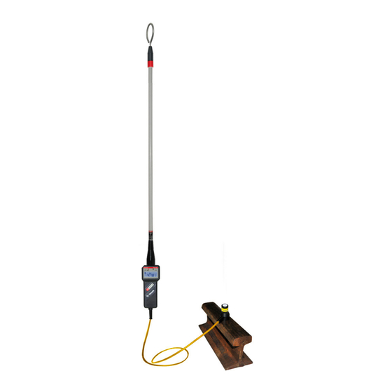
Attention! Observe user instructions! Indicates EC conformity Device for live working This device has to be disposed of according to the applicable regulations and laws (for Europe: WEEE 2012/19/EU). Please contact service@tietzsch.de in regard to the return of old devices. - Page 3 1. Application The MultiSafe DSP-UB 3 is a two-pole voltage tester to test on railway lines with lateral power supply (3rd-rail). Thanks to its green and red LEDs, the display is easy to see even in dark surroundings. The firmly attached magnet and the extension allowing greater safety distances and ease of handling.
- Page 4 Workings may only be performed with appropriate personal protective equipment. Observe the minimum object distance to other plant components that are energized or earthed and use personal protective equipment as speci- fied by national accident prevention regulations (in Germany: DGUV V3 or DIN EN 50110-1). The function of the voltage tester must be checked briefly before and whenever possible after the use.
- Page 5 3.2 Establish contact with the earth Place the contact magnet on the bare rail. The contact surface must be clean and free from coarse rust. 3.3 Checking the function with the integrated self-test Step 1 – Test of the display The device must be switched off for the self-test.
- Page 6 4. Measuring and testing Attention! The function test (see 3.3) has to be performed successfully. The voltage tester does not switch on automatically when voltage is applied. After a successful self-test, contact the power rail with the O-electrode of the extension. The O-electrode must be rotated so that the busbar is touched as shown below.
- Page 7 4.1 Voltage indication green LEDs flash display illumination white no voltage (voltage < 260 V) red LEDs lights up display illumination red voltage! (voltage > 260 V) DC / AC voltage, polarity The type of voltage is represented by the symbols „~“...
- Page 8 5. Battery The latest battery status is symbolised by a three-stage battery indicator on the display. indication of battery status replace the battery soon – few measurements possible (Battery symbol flashing: no further measurements admissible!) Attention! When the empty battery symbol flashes, then no more measurements can be performed and the battery has to be replaced immediately.
- Page 9 6. Maintenance / Storage 6.1 General information The MultiSafe DSP-UB 3 is completely maintenance- free. Nevertheless, observe the following information in order to maintain safe operation: Always keep the voltage tester dry and clean. The housing can be cleaned with a cloth dampened with isopropyl (alcohol) or soapy water.
- Page 10 9. Technical data Type/ Nominal voltage range: DSP-UB 3: 10 ... 3000 V AC 10 ... 3000 V DC Nominal frequency range: DC/15 ... 500 Hz Measurement range: 10 ... 3000 V AC 10 ... 3000 V DC ± 3 % + 5 D Input resistance: 448 kΩ...
Need help?
Do you have a question about the MultiSafe DSP-UB 3 and is the answer not in the manual?
Questions and answers