Advertisement
Available languages
Available languages
Quick Links
Bedienungsanleitung
User Instructions
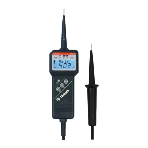
MultiSafe DSP 4
Spannungs- und Durchgangsprüfer
Voltage-Continuity Tester
Rudolph Tietzsch GmbH & Co. KG
Willringhauser Straße 18
58256 Ennepetal
GERMANY
Telefon: +49 2333-75989
info@tietzsch.de
www.tietzsch.de
DSP4_BA_04-2016
Via Acquanera, 29
tel. 031.526.566 (r.a.) fax 031.507.984
info@calpower.it
22100 Como
www.calpower.it
Advertisement

Subscribe to Our Youtube Channel
Related Manuals for Tietzsch MultiSafe DSP 4


Summary of Contents for Tietzsch MultiSafe DSP 4
- Page 1 Via Acquanera, 29 22100 Como Bedienungsanleitung tel. 031.526.566 (r.a.) fax 031.507.984 User Instructions info@calpower.it www.calpower.it MultiSafe DSP 4 Spannungs- und Durchgangsprüfer Voltage-Continuity Tester Rudolph Tietzsch GmbH & Co. KG Willringhauser Straße 18 58256 Ennepetal GERMANY Telefon: +49 2333-75989 info@tietzsch.de www.tietzsch.de DSP4_BA_04-2016...
- Page 2 Einschaltdauer bei höchster Nennspannung Erholzeit nach Prüfung mit höchster Nennspannung Gerät zum Arbeiten unter Spannung Dieses Gerät muss gemäß den geltenden Richtlinien und Gesetzen (für Europa: WEEE 2012/19/EU) fachgerecht entsorgt werden. Bei Fragen zur Altgeräte-Rücknahme wenden Sie sich bitte an service@tietzsch.de...
- Page 3 1. Anwendung Der MultiSafe DSP 4 ist ein zweipoliger, digital anzeigender Spannungsprüfer, zertifiziert nach DIN EN 61243-3 (VDE 0682 Teil 401), kombiniert mit einem Durchgangs-, Phasen-, Polaritäts- und Dreh- feldprüfer. Mit diesem können Sie das Vorhanden- sein und die Höhe von Wechsel- oder Gleichspan- nung von 24 V bis 1000 V bei Frequenzen bis 4 kHz feststellen.
- Page 4 Bitte beachten Sie folgende Sicherheitsvorkehrungen: Die Spannungsangaben auf dem MultiSafe DSP 4 sind Nennwerte. Der Spannungsprüfer darf nur in Anlagen mit dem angegebenen Nennspannungsbereich benutzt werden. Eine einwandfreie Anzeige ist nur im Tempera- turbereich von - 15° C ... + 45° C sichergestellt.
- Page 5 3. Inbetriebnahme 3.1 Batterie In Ihr Gerät ist bereits eine 9 V-Batterie nach IEC 6LR61 / 6LF22 / 6LP3146 eingesetzt. Der Batte- riezustand wird durch das Batteriesymbol auf dem Display angezeigt (siehe Abschnitt 6.). 3.2 Prüfen von Anzeige und Funktion (Eigentest) Nach EN 50110-1 (DIN VDE 0105 -100) müssen Spannungsprüfer mindestens unmittelbar vor und nach Möglichkeit auch nach dem Gebrauch auf...
- Page 6 4. Messen und Prüfen 4.1 Allgemeine Hinweise Der Spannungsprüfer schaltet sich beim Anlegen einer Spannung ab 24 V automatisch ein. Falls Durchgangsprüfung eingeschaltet ist, schaltet das Gerät automatisch auf Spannung prüfen um. Das Gerät wählt automatisch den Messbereich (siehe Abschnitt 5.), welcher dem anliegenden Spannungs- wert entspricht.
- Page 7 Anzeige „OL“ und eine akustische Warnmeldung. In diesem Fall muss die Prüfung sofort abgebrochen werden! 4.3 Phase und Drehfeldrichtung prüfen Der MultiSafe DSP 4 ist mit zwei dreieckigen LEDs ausgestattet, um Drehfeldrichtungsprüfungen anzuzeigen. Achtung! Diese Prüfungen funktionieren erst ab Spannungen von 165 V (50 Hz) gegen Erde.
- Page 8 4.3.1 Phasenprüfung Die Ermittlung des Außenleiters erfolgt durch Anlegen der Prüfspitze +L1 an den Leiter. Wird „POL“ auf dem Display angezeigt, so ist der Leiter spannungsführend. Achtung! Einpolige Prüfungen sind nicht für die Festellung der Spannungsfreiheit geeignet. 4.3.2 Prüfen der Drehfeldrichtung Das Drehfeld zwischen zwei Phasen im geerdeten Drehstromnetz wird durch Anlegen beider Prüfspitzen und Umfassen der Handhabe des Anzeigeteils wie...
- Page 9 5. Technische Daten DSP 4 Mess- Messbereiche Auflösung Frequenz- Eigen- größe (automatische bereich/ abweichung Bereichswahl) Messstrom 0,10 V ... 8,99 V 0,01 V ±1,5 % 9,0 V ... 99,9 V 0,1 V +3 Digits 100 V ... 1500 V 1,0 V ... 99,9 V 15 Hz ...
- Page 10 Schutzart: IP 65 Verbindungsleitung: PUR-Mantelleitung 1000 V, 1 m Abmessungen: Prüfspitze mit Anzeigeteil 240 x 62 x 39 mm Gewicht: 270 g (inkl. Batterie) 6. Batterie 6.1 Batterieanzeige Der aktuelle Zustand der Batterie wird über die drei- stufige Batterieanzeige im Display angezeigt. Anzeige des Batteriezustandes Batterie ersetzen –...
- Page 11 Werkstätten zulässig. Bei Beschädigung des Gerätes, Ausfall des Funk tionstests nach Abschnitt 3.2 oder zur detaillierten Überprüfung/Kalibrierung wenden Sie sich bitte an: service@tietzsch.de oder senden Sie das Gerät mit Fehlerbeschreibung an den Hersteller (Adresse siehe Seite 1). 9. Eingeschränkte Garantie und Haftungsbeschränkung...
- Page 12 10. Zubehör optional Allgemeine Hinweise Es dürfen nur aufschraubbare oder aufsteckbare Verlängerungen/Adapter DSP-S vom Hersteller verwendet werden. Für fest aufschraubbare Verlän- gerungen müssen beide Prüfspitzen des MultiSafe DSP mit Gewinde ausgestattet sein. Achtung! Die Verbindung zwischen Prüfspitze und Spannungsprüfer ist jeweils zu kontrollieren! Überprüfen Sie die Funktion an einer bekannten Spannungsquelle oder mit dem Eigentest.
- Page 13 Erhältliches Zubehör Art.Nr. Beschreibung 84019 DSP...G Gewindesatz für beide Spitzen des DSP 84313 LSP-S500-* DSP/LSP-Verlängerungsspitze 500 mm, isoliertes Edelstahlrohr aufsteckbar, 1000 V 84010 DSP-S500-* DSP-Verlängerungsspitze 500 mm, isoliertes Edelstahlrohr aufschraubbar, 1000 V 84014 DSP-S940-* DSP-Verlängerungsspitze 940 mm, GFK, aufschraubbar, 1000 V 84321 DSP-S20-A DSP-Einstechspitze für Erdka-...
- Page 15 User Instructions MultiSafe DSP 4 Voltage-Continuity Tester Rudolph Tietzsch GmbH & Co. KG Willringhauser Straße 18 58256 Ennepetal GERMANY Phone: +49 2333-75989 info@tietzsch.de www.tietzsch.de DSP4_BA_04-2016...
- Page 16 Recovery time after tests with highest nominal voltage Device for live working This device has to be disposed of according to the appli- cable regulations and laws (for Europe: WEEE 2012/19/EU). Please contact service@tietzsch.de in regard to the return of old devices.
- Page 17 1. Application The MultiSafe DSP 4 is a two-pole voltage tester with digital display. It complies with DIN EN 61243-3 (VDE 0682 part 401) and is provided with continuity and phase tester, polarity tester and phase sequence indicator. With this device you can determine the...
- Page 18 Please observe the following safety precautions: The voltages indicated on the MultiSafe DSP 4 are rated voltages. The voltage tester may only be used in systems working within this rated voltage range. Faultless indication of display values is only guaranteed between -15°C ...
- Page 19 3. Putting into operation 3.1 Battery Your instrument is already supplied with a 9 V block battery in accordance with IEC 6LR61 / 6LF22 / 6LP3146. The battery status is indicated by a battery symbol on the display (see section 6). 3.2 Testing correct display and function (self-test) In accordance with EN 50110-1 voltage testers must be checked if they function correctly, briefly before...
- Page 20 4. Measuring and testing 4.1 General information The voltage tester switches on automatically when a voltage of at least 24 V is applied. If the function continuity testing had been activated, the device switches automatically to voltage testing. The in- strument automatically selects the measuring range that corresponds to the applied voltage (see section 5.).
- Page 21 In this case, the test procedure must be stopped immediately! 4.3 Testing phase and phase sequence The MultiSafe DSP 4 is equipped with 2 triangular LEDs for the indication of phase sequence tests. Attention! These tests can be performed at a nominal voltage of at least 165 V (50 Hz) against earth.
- Page 22 4.3.2 Testing phase sequence To determine the phase sequence between two phases in the phase network apply both test electrodes, clasp the handle of the display part and proceed as follows (example 230/400 V): - Search for the phase conductors using one pole (see phase test).
- Page 23 5. Technical data DSP 4 Measure- Measuring Resolution Frequency Intrinsic ment ranges range/ error (auto-ranging) measuring 0.10 V ... 8.99 V 0.01 V ±1.5 % 9.0 V ... 99.9 V 0.1 V +3 digits 100 V ... 1500 V 1.0 V ... 99.9 V 15 Hz ...
- Page 24 Protection category: IP 65 Connecting line: PUR hose cable 1000 V, 1m Dimensions: test electrode with display part 240 x 62 x 39 mm Weigth: 270 g (incl. battery) 6. Battery 6.1. Battery indication The latest battery status is symbolised by a three- stage battery indicator.
- Page 25 In case of damages on the device or failure of the function test according to section 3.2 or for detailed inspection/calibration, please contact: service@tietzsch.de or send the device and a description of failure back to the manufacturer (address see page 1).
- Page 26 10. Accessories optional General information Only screwable or attachable extensions/adapters DSP-S provided by the manufacturer may be used. To use securely compact screwable extensions both test electrodes of the MultiSafe DSP must be provided with thread. Attention! The connection between test probe and voltage tester has to be controlled in each case! Check function at a known voltage source or by self-test.
- Page 27 Available accessories Art.no. Type Description 84019 DSP...G Thread set for both probes of the DSP 84313 LSP-S500-* DSP / LSP extension 500 mm isulated stainless steel tube attachable, 1000 V 84010 DSP-S500-* DSP extension 500 mm isulated stainless steel tube screwable, 1000 V 84014 DSP-S900-*...
- Page 28 Via Acquanera, 29 22100 Como tel. 031.526.566 (r.a.) fax 031.507.984 info@calpower.it www.calpower.it...
Need help?
Do you have a question about the MultiSafe DSP 4 and is the answer not in the manual?
Questions and answers