Beckhoff C6920 Installation And Operating Instructions Manual
Control cabinet pcs
Hide thumbs
Also See for C6920:
- Installation and operating instructions manual (35 pages) ,
- Manual (52 pages) ,
- Manual (53 pages)

Related Manuals for Beckhoff C6920


Summary of Contents for Beckhoff C6920
- Page 1 Installation and Operating instructions for Control Cabinet PCs C6920, C6925 Version: 1.5 Date: 2007-01-30...
-
Page 3: Table Of Contents
Description of safety symbols Basic safety measures Operator's obligation to exercise diligence Operator requirements Product Description Appropriate Use Access to the drives Status-LEDs Fan cartridge C6920 Interfaces Power Supply Network connection USB-Interfaces DVI (Digital Visual Interface) Serial interface Fieldbus Additional plug-in cards (optional) - Page 4 Table of contents Troubleshooting Fault correction Service and Support Beckhoff's branch offices and representatives Beckhoff headquarters Beckhoff Support Beckhoff Service Assembly dimensions Appendix Technical data Approvals FCC: Federal Communications Commission Radio Frequency Interference Statement FCC: Canadian Notice C6920/ 25...
-
Page 5: General Notes
© This documentation is copyrighted. Any reproduction or third party use of this publication, whether in whole or in part, without the written permission of Beckhoff Automation GmbH, is forbidden. Description of safety symbols The following safety symbols are used in this operating manual. They are intended to alert the reader to the associated safety instructions. -
Page 6: Basic Safety Measures
If metal objects such as screws or tools fall onto operating circuit boards. • If connecting cables internal to the PC are removed or inserted during operation. • If plug-in cards are removed or inserted when the PC is switched C6920/ 25... -
Page 7: Operator's Obligation To Exercise Diligence
Read the operating Every user of the Industrial PC must have read these operating instructions instructions. Software knowledge Every user must be familiar with any of the functions of the software installed on the PC that he can reach. C6920/ 25... -
Page 8: Product Description
C6920 C6925 C6920/ 25 Configuration The C6920 is fitted with a fan cartridge with observated double ball bearing fans, exchangeable at the front. The C6925 is a fanless Industrial PC with passive cooling. Access to the drives Access to hard-disk... -
Page 9: Status-Leds
FB RUN (Fieldbus activ): green Activ Not activ FB Error (Fieldbus Error): Error Fan cartridge C6920 View from the top Exchanging the fan For exchanging the fan cartridge, first solve the knurled screw (1). The cartridge cartridge (2) can then be folded down. -
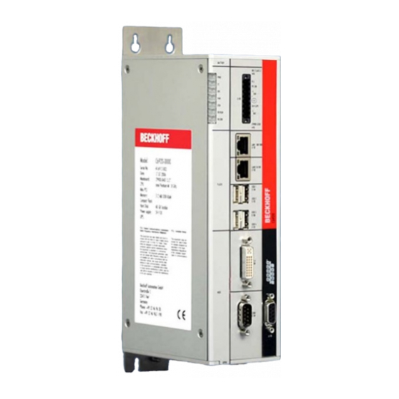
Page 10: Interfaces
Product Description Interfaces Interfaces to the X106 X104 X101 X103 X102 X109 X108 C6920/ 25 Industrial PCs X105 X107 X110 Power Supply Power supply The power supply for the Industrial PC is established via the socket (X101). Network connection Network 100/1000BASE-T The RJ-45 connector (X102) allows the PC to be connected to a 100/1000BASE-T Local Area Network (LAN). -
Page 11: Installation Instructions
4. Please keep the associated paperwork. It contains important information for handling the unit. 5. Check the contents for visible shipping damage. 6. If you notice any shipping damage or inconsistencies between the contents and your order, you should notify Beckhoff Service. C6920/ 25... -
Page 12: Installation Of The Pc In The Control Cabinet
Installation Instructions Installation of the PC in the control cabinet The C6920/ 25 Industrial PCs are designed for mounting in control cabinets for machine and plant engineering applications. The ambient conditions specified for operation must be observed (see chapter Technical data). -
Page 13: Power Supply Connection
8-pole plug connector . Pin assignment for Function connecting the switch, the Battery Pack (with USV) power supply and the 1 2 3 4 5 6 7 8 battery pack (optional) UPS+ (Output) 24 V DC Power Supply PC_ON Power-Status C6920/ 25... -
Page 14: Fitting The Cable
Tighten the lacing cord and pinch off the plastic strap. Fixing the upper part of the strain relief housing Fix the upper part of the strain relief housing by snapping it onto the lower part. C6920/ 25... -
Page 15: Connecting Power Supply
Battery - Pole, current loading maximum 1.4 A. • After the PC is disconnected from power supply via UPS software, the UPS output is switched to 0V too. A connected Panel is thus switched off, a total-discharge of the battery is not possible. C6920/ 25... -
Page 16: Wiring Diagram
Installation Instructions Wiring diagram Wiring according to the wiring diagram (the circuit of PC_ON and Power- Status is symbolical): Wiring diagram external switch and power supply C6920/ 25... -
Page 17: Connecting Devices
2. Insert the power supply cable that you have assembled into the Industrial PC's power supply socket. Then connect it to your external 24 V power supply. If a 24 V UPS is installed, the same type of rechargeable battery must be used. Warning C6920/ 25... -
Page 18: Operating Instructions
If the PC was ordered without operating system, you have to install the operating system and the driver software for any auxiliary hardware yourself. Please follow the instructions in the documentation for the operating system and the additional devices. C6920/ 25... -
Page 19: Maintenance
The device must be fully dismantled in order to dispose of it. The housing can be sent for metal recycling. Observe national Electronic parts such as disk drives and circuit boards must be disposed of electronics scrap in accordance with national electronics scrap regulations. regulations C6920/ 25... -
Page 20: Ups Software Components (Optional)
The driver software comes with a detailed help function. System The help files can be called up either directly from the configuration register by clicking the Help button, or under via Start > Programs > Beckhoff > UPS software components. C6920/ 25... -
Page 21: Troubleshooting
Nothing happens after the Industrial No power supply to the Industrial Check power supply cable. PC has been switched on Other cause. Call Beckhoff Service. The Industrial PC does not boot Floppy disk or CD in the drive. Remove floppy disk or CD fully and press any key. -
Page 22: Service And Support
Fax: +49(0)5246/963-198 e-mail: info@beckhoff.com Beckhoff Support Support offers you comprehensive technical assistance, helping you no only with the application of individual Beckhoff products, but also with other, wide-ranging services: • world-wide support • design, programming and commissioning of complex automation systems •... -
Page 23: Assembly Dimensions
Assembly dimensions Assembly dimensions The following pages show diagrams of the Industrial PCs, with dimensions in mm. The assembly of the unit must take place with the orientation diagrammed here. Warning Industrial-PC C6920 side view front view top view C6920/ 25... - Page 24 Assembly dimensions The assembly of the unit must take place with the orientation diagrammed here. Warning Industrial-PC C6925 front view side view top view C6920/ 25...
-
Page 25: Appendix
Appendix Appendix Technical data Industrial-PC C6920 Dimensions (W x H x D): 65 x 231 x 116 mm (without mounting plate) Weight: 1.9 kg (basic configuration) Industrial-PC C6925 Dimensions (W x H x D): 65 x 208 x 116 mm (without mounting plate) Weight: 1.85 kg (basic configuration)
Need help?
Do you have a question about the C6920 and is the answer not in the manual?
Questions and answers