Table of Contents
Advertisement
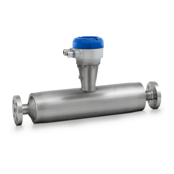
OPTIMASS / 300 / 010
Guidelines for the use of Coriolis meters in hazardous areas
• • 1 1 0 0 0 0 0 0 S S e e r r i i e e s s T T w w i i n n S S t t r r a a i i g g h h t t T T u u b b e e C C o o r r i i o o l l i i s s M M a a s s s s F F l l o o w w m m e e t t e e r r
• • 2 2 0 0 0 0 0 0 S S e e r r i i e e s s T T w w i i n n S S t t r r a a i i g g h h t t T T u u b b e e C C o o r r i i o o l l i i s s M M a a s s s s F F l l o o w w m m e e t t e e r r
• • 3 3 0 0 0 0 0 0 S S e e r r i i e e s s S S i i n n g g l l e e Z Z T T u u b b e e C C o o r r i i o o l l i i s s M M a a s s s s F F l l o o w w m m e e t t e e r r
• • 4 4 0 0 0 0 0 0 S S e e r r i i e e s s T T w w i i n n U U T T u u b b e e C C o o r r i i o o l l i i s s M M a a s s s s F F l l o o w w m m e e t t e e r r
• • 7 7 0 0 0 0 0 0 S S e e r r i i e e s s S S i i n n g g l l e e S S t t r r a a i i g g h h t t T T u u b b e e C C o o r r i i o o l l i i s s M M a a s s s s F F l l o o w w m m e e t t e e r r
• • 8 8 0 0 0 0 0 0 k k S S e e r r i i e e s s T T w w i i n n U U T T u u b b e e C C o o r r i i o o l l i i s s M M a a s s s s F F l l o o w w m m e e t t e e r r
• • 8 8 0 0 0 0 0 0 / / 9 9 0 0 0 0 0 0 S S e e r r i i e e s s T T w w i i n n U U T T u u b b e e C C o o r r i i o o l l i i s s M M a a s s s s F F l l o o w w m m e e t t e e r r
• • O O P P T T I I G G A A S S 4 4 0 0 0 0 0 0
• • O O P P T T I I G G A A S S 5 5 0 0 0 0 0 0
• • M M F F C C 3 3 0 0 0 0 M M a a s s s s F F l l o o w w C C o o n n v v e e r r t t e e r r
Advertisement
Table of Contents

Related Manuals for KROHNE OPTIMASS 1000 Series


Summary of Contents for KROHNE OPTIMASS 1000 Series
- Page 1 OPTIMASS / 300 / 010 Guidelines for the use of Coriolis meters in hazardous areas • • 1 1 0 0 0 0 0 0 S S e e r r i i e e s s T T w w i i n n S S t t r r a a i i g g h h t t T T u u b b e e C C o o r r i i o o l l i i s s M M a a s s s s F F l l o o w w m m e e t t e e r r •...
-
Page 2: Table Of Contents
CONTENTS OPTIMASS 1. Introduction 1.1 General ..............5 1.2 MFC 300F &... - Page 3 Handling • Lifting • Supporting and fixing the meter • Cabling and connections. • If the product does not operate normally, refer to the handbook or consult a qualified KROHNE service engineer. There are no operator-serviceable parts inside the product.
- Page 4 • KROHNE will not be liable for any damage of any kind by using this device, including, but not limited to: direct; indirect; incidental; punitive and consequential damages.
-
Page 5: Introduction
INTRODUCTION OPTIMASS 1.1 General The OPTIMASS / OPTIGAS flowmeter systems consist of a mass flow sensor and a mass flow converter or a mass flow sensor and associated apparatus. The separate mass flow sensor with a mass flow converter is identified as: •... -
Page 6: Mfc 300F & Mfc 300F T6
1.2 MFC 300F & MFC 300F T6 The MFC 300F & MFC 300F T6 have intrinsically safe connections to the mass flow sensor with either increased safety or intrinsically safe signal outputs. The signal output connection compartment can be configured with protection type Ex d or Ex e. The marking is as follows: F F o o r r E E x x i i o o u u t t p p u u t t s s E E x x d d c c o o n n n n e e c c t t i i o o n n c c o o m m p p a a r r t t m m e e n n t t E E x x e e c c o o n n n n e e c c t t i i o o n n c c o o m m p p a a r r t t m m e e n n t t... -
Page 7: Optimass 1000 / 1010C / 1300C
1.3 OPTIMASS 1000 / 1010C / 1300C The OPTIMASS 1000 / 1010C mass flow sensor / mass flow meter is designed with intrinsically safe protection type. The marking for the OPTIMASS 1000 / 1010C for versions with or without heating jacket / insulation is as follows: II 1/2 G Ex ib IIC T4...T1 Ga/Gb II 2 D Ex ib IIIC T175°C Db The input connections to the OPTIMASS 1010C for use with associated apparatus have the... -
Page 8: Optimass 1000 T6 / 1010C T6 / 1300C T6
1.4 OPTIMASS 1000 T6 / 1010C T6 / 1300C T6 The OPTIMASS 1000 T6 / 1010C T6 mass flow sensor / mass flow meter is designed with intrinsically safe protection type. The marking for the OPTIMASS 1000 / 1010C T6 for versions with or without heating jacket / insulation is as follows: II 1/2 G Ex ib IIC T6...T1 Ga/Gb II 2 D Ex ib IIIC T165°C Db... -
Page 9: Optimass 2000 / 2010C / 2300C
1.5 OPTIMASS 2000 / 2010C / 2300C The OPTIMASS 2000 / 2010C mass flow sensors / mass flow meters are designed with intrinsically safe protection type. The marking for the OPTIMASS 2000 / 2010C is as follows: II 1/2 G Ex ib IIC T6...T1 Ga/Gb II 2 D Ex ib IIIC T150°C Db The input connections to the OPTIMASS 2010C for use with associated apparatus have the following maximum values:... -
Page 10: Optimass 3000 / 3010C / 3300C
1.6 OPTIMASS 3000 / 3010C / 3300C The OPTIMASS 3000 / 3010C mass flow sensors / mass flow meters are designed with intrinsically safe protection type. The marking for the OPTIMASS 3000 / 3010C is as follows: No heating jacket / insulation Heating jacket / insulation II 2 G Ex ib IIC T6..T1 Gb II 2 G Ex ib IIC T6..T1 Gb... -
Page 11: Optimass / Optigas 4000 / 4010C
1.7 OPTIMASS 4000 / 4010C / OPTIGAS 4000 / 4010C The OPTIMASS 4000 / 4010C OPTIGAS 4000 / 4010C mass flow sensors / mass flow meters are designed with intrinsically safe protection type. The marking for the OPTIMASS 4000 / 4010C / OPTIGAS 4000 / 4010C is as follows: II 1/2 G Ex ib IIC T4...T1 Ga/Gb II 2 D Ex ib IIIC T210°C Db... -
Page 12: Optigas 5000 / 5010C / 5300C
1.8 OPTIGAS 5000 / 5010C / 5300C The OPTIGAS 5000 / 5010C mass flow sensor / mass flow meter is designed with intrinsically safe protection type. The marking for the OPTIGAS 5000 / 5010C for versions with or without heating jacket / insulation is as follows: II 2 G Ex ib IIC T4..T1 Gb The input connections to the OPTIGAS 5010C for use with associated apparatus have the following maximum values:... -
Page 13: Optimass 7000 / 7010C / 7300C
1.9 OPTIMASS 7000 / 7010C / 7300C The OPTIMASS 7000 / 7010C mass flow sensors / mass flow meters are designed with intrinsically safe protection type. The marking for the OPTIMASS 7000 / 7010 C is as follows: No heating jacket / insulation Heating jacket / insulation II 1/2 G Ex ib IIC T6..T1 Ga/Gb II 1/2 G Ex ib IIC T6..T1 Ga/Gb... -
Page 14: Optimass 8000K / 8010Kc / 8300Kc
1.10 OPTIMASS 8000k / 8010kC / 8300kC The OPTIMASS 8000k / 8010kC mass flow sensors / mass flow meters are designed with intrinsically safe protection type. The marking for the OPTIMASS 8000k / 8010kC is as follows: II 1/2 G Ex ib IIC T4...T1 Ga/Gb II 2 D Ex ib IIIC T210°C Db The input connections to the OPTIMASS 8010kC / 8010kC for use with associated apparatus have the following maximum values:... -
Page 15: Optimass 8000 / 8010C / 8300C / 9000 / 9010C
1.11 OPTIMASS 8000 / 8010C / 8300C / 9000 / 9010C The OPTIMASS 8000 / 8010C and OPTIMASS 9000 / 9010C mass flow sensors / mass flow meters are designed with intrinsically safe protection type. The marking for the OPTIMASS 8000 / 8010C is as follows: II 1/2 G Ex ib IIC T4...T1 Ga/Gb II 2 D Ex ib IIIC T280°C Db... -
Page 16: Data Plates
1.12 Data Plates The data plate on the connection box of separate mass flow sensors typically contains the fol- lowing information: Company logo and address Model/size Year of Manufacture Serial Number Handbook Publication Number Identification Number of the notified body, as required by Directive 94/95 EC, Annex IV Ex Specific Requirements (example shown) Certificate Number Ex Marking (Example Shown) -
Page 17: Temperature Limits
TEMPERATURE LIMITS OPTIMASS 2.1 General Due to the influence of the media temperature, mass flow sensors and compact mass flow meters are not allocated to any fixed temperature class. For allocation regarding the non-insu- lated and heated/insulated versions, please refer to the tables below. The temperature limits below apply under the following conditions: •... -
Page 18: Optimass 1000 / 1010C / 1300C
* Only for equipment configurations according to the table in section 2.2 The cable supplied by KROHNE is designed for a continuous working temperature of up to 105°C. Alternative cabling must be a heat-resistant type with a continuous minimum working temperature of 80°C. -
Page 19: Optimass 1000 T6 / 1010C T6 / 1300C T6
2.4 OPTIMASS 1000 T6 / 1010C T6 / 1300C T6 The OPTIMASS 1000 T6 / 1010C T6 / 1300C T6 is suitable for temperature classes T6….T1 according to the following table: OPTIMASS 1000 T6 / 1010C T6 with or without heating jacket / insulation Ambient Temp. - Page 20 * Only for equipment configurations according to the table in section 2.2 The cable supplied by KROHNE is designed for a continuous working temperature of up to 105°C. Alternative cabling must be a heat-resistant type with a minimum continuous working...
-
Page 21: Optimass 2000 / 2010C
* Only for equipment configurations according to the table in section 2.2 The cable supplied by KROHNE is designed for a continuous working temperature of up to 105°C. Alternative cabling must be a heat-resistant type with a continuous working tempera-... -
Page 22: Optimass 3000 / 3010C / 3300C 7000 / 7010C / 7300C
2.6 OPTIMASS 3000 / 3010C / 3300C / 7000 / 7010C / 7300C The OPTIMASS 3000 / 3010C / 3300C and OPTIMASS 7000 / 7010C / 7300C are suitable for temperature classes T6….T1 according to the following tables: OPTIMASS 3000 / 3010C and 7000 / 7010 C without heating jacket / insulation Ambient Temp. - Page 23 * Only for equipment configurations according to the table in section 2.2 The cable supplied by KROHNE is designed for a continuous working temperature of up to 105°C. Alternative cabling must be a heat-resistant type with a minimum continuous working...
-
Page 24: Optimass 4000 / 4010C / Optigas 4000 / 4010C
T195 T2 – T1 T210 The cable supplied by KROHNE is designed for a continuous working temperature of up to 105°C. Alternative cabling must be a heat-resistant type with a continuous working tempera- ture of 80°C. 2.8 OPTIMASS 8000k / 8010kC / 8300kC The OPTIMASS 8000k / 8010kC / 8300kC is suitable for temperature classes T4….T1 according... - Page 25 * Only for equipment configurations according to the table in section 2.2 The cable supplied by KROHNE is designed for a continuous working temperature of up to 105°C. Alternative cabling must be a heat-resistant type with a continuous minimum working temperature of 80°C.
-
Page 26: Optimass 8000 / 8010C / 8300C
* Only for equipment configurations according to the table in section 2.2 The cable supplied by KROHNE is designed for a continuous working temperature of up to 105°C. Alternative cabling must be a heat-resistant type with a continuous working tempera-... -
Page 27: Optimass 9000 / 9010C
T195 T290 T385 The cable supplied by KROHNE is designed for a continuous working temperature of up to 105°C. Alternative cabling must be a heat-resistant type with a continuous working tempera- ture of 80°C. 2.11 OPTIGAS 5000 / 5010C / 5300C The OPTIGAS 5000 / 5010C / 5300C is suitable for temperature classes T4….T1 according to the... -
Page 28: Painted Options
2.12 Painted options OPTIMASS 1000, 1010C, 1000 T6, 1010C T6, 1300C, 1300C T6, 2000, 2010C, 2300C, 3300C, 4000, 4010C, 7000, 7010C, 7300C, 8000k, 8010kC, 8300kC and OPTIGAS 4000, 4010C are available with a paint finish to prevent corrosion. Where the meter is remote, the MFC 300F / T6 is also available with a painted finish. -
Page 29: Connection Of Separated Systems
The maximum permitted total capacitance and inductance for the connecting cable is : C L = 195 nF L L = 310 μH • Cable supplied by Krohne has the following parameters: C L ’ 200pF/m < L L ’... -
Page 30: Terminal Diagrams
3.4 Terminal Connections MFC 300F Mass flow converter junction box OPTIMASS / OPTIGAS Mass flow sensor junction box M M F F C C 3 3 0 0 0 0 F F M M a a s s s s f f l l o o w w c c o o n n v v e e r r t t e e r r j j u u n n c c t t i i o o n n b b o o x x The Power Supply Circuit is connected to terminals + and –... -
Page 31: Electrical Connections
ELECTRICAL CONNECTIONS OPTIMASS 4.1 General • The MFC 300F mass flow converter or OPTIMASS / OPTIGAS x300C mass flow meter must be included in the equipotential bonding system of the installation using the equipotential bonding terminal on the mass flow converter housing wall bracket or mass flow meter housing mounting stem respectively. -
Page 32: Non-Ex I Signal I/O Connections
The exact I/O-configuration for circuits A, B, C and D is order-specific and can be determined by the CG32 number shown on the converter - check the data on the back of the MFC300 electronic unit. The CG32 number contains 10 characters of which the last three (XYZ) determine the I/O con- figuration (I/O circuits): CG32 pos 1.. - Page 33 • The options separated with “/” are software selectable (can be changed by user) • The options separated by “or” are hardware versions (must be ordered as such) • All outputs are passive unless otherwise indicated • HighC means High Current input/output, Namur means input/output to Namur recommen- dations O O v v e e r r v v i i e e w w o o f f p p o o s s s s i i b b l l e e c c o o m m b b i i n n a a t t i i o o n n s s , , d d e e f f i i n n e e d d b b y y t t h h e e C C G G 3 3 2 2 n n u u m m b b e e r r C C h h a a r r a a c c t t e e r r s s...
-
Page 34: Ex I Signal I/O Connections
4.3 Ex i signal I/O connections Following intrinsically safe signal I/Os are available: I I / / O O P P C C B B I I / / O O f f u u n n c c t t i i o o n n s s Ex ia IIC Current Output + HART communication Ui =30V, Ii = 100 mA, Pi = 1,0 W... - Page 35 O O v v e e r r v v i i e e w w p p o o s s s s i i b b l l e e C C G G 3 3 2 2 n n u u m m b b e e r r s s w w i i t t h h E E x x i i a a i i n n / / o o u u t t p p u u t t s s C C h h a a r r a a c c t t e e r r s s N N a a m m e e I I / / O O T T e e r r m m i i n n a a l l s s A A , , A A - -...
-
Page 36: Service And Maintenance
The specimen shown in appendix 1 can be photocoppied and used and it is also available on the KROHNE website as a word file. Simply download and use the tabulator key to go from one fill- out field to the next. Please attach the form to the returned device... - Page 37 KROHNE Order No. or Series No.: ........
- Page 40 Denmark Peru KROHNE Messtechnik KROHNE Austria Ges.m.b.H. Singapore Ecuador Poland GmbH & Co. KG Modecenterstraße 14 Tokyo Keiso - KROHNE Singapore Pte. Ltd. Egypt Portugal Ludwig-Krohne-Str. A-1030 Wien 14, International Business Park, Finland Romania D-47058 Duisburg TEL.: +43(0)1/203 45 32...
Need help?
Do you have a question about the OPTIMASS 1000 Series and is the answer not in the manual?
Questions and answers