KROHNE OPTIFLUX 5000 Handbook
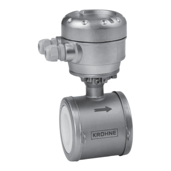
Electromagnetic flowmeter in sandwich version
Hide thumbs
Also See for OPTIFLUX 5000:
- Handbook (28 pages) ,
- Quick start manual (24 pages) ,
- Supplementary instructions manual (40 pages)
Table of Contents
Advertisement
OPTIFLUX 5000
OPTIFLUX 5000
OPTIFLUX 5000
OPTIFLUX 5000
Electromagnetic flowmeter in sandwich version
The documentation is only complete when used in combination with the relevant
documentation for the signal converter.
© KROHNE 03/2017 - 4000686204 - MA OPTIFLUX 5000 SW R04 en
Handbook
Handbook
Handbook
Handbook
Advertisement
Table of Contents

Related Manuals for KROHNE OPTIFLUX 5000


Summary of Contents for KROHNE OPTIFLUX 5000
- Page 1 OPTIFLUX 5000 Handbook Handbook Handbook Handbook Electromagnetic flowmeter in sandwich version The documentation is only complete when used in combination with the relevant documentation for the signal converter. © KROHNE 03/2017 - 4000686204 - MA OPTIFLUX 5000 SW R04 en...
- Page 2 All rights reserved. It is prohibited to reproduce this documentation, or any part thereof, without the prior written authorisation of KROHNE Messtechnik GmbH. Subject to change without notice. Copyright 2017 by KROHNE Messtechnik GmbH - Ludwig-Krohne-Str. 5 - 47058 Duisburg (Germany) www.krohne.com 03/2017 - 4000686204 - MA OPTIFLUX 5000 SW R04 en...
-
Page 3: Table Of Contents
3.8 Flange deviation ......................16 3.9 Control valve........................16 3.10 Pump..........................17 3.11 Air venting and vacuum forces..................17 3.12 Mounting position ......................18 3.13 Mounting ........................19 3.13.1 Torques and pressure......................19 03/2017 - 4000686204 - MA OPTIFLUX 5000 SW R04 en www.krohne.com... - Page 4 5.3.2 Form (for copying) to accompany a returned device............24 5.4 Disposal .......................... 24 6 Technical data 6.1 Measuring principle......................25 6.2 Technical data......................... 26 6.3 Measuring accuracy ....................... 31 6.4 Dimensions and weights ....................33 7 Notes www.krohne.com 03/2017 - 4000686204 - MA OPTIFLUX 5000 SW R04 en...
-
Page 5: Safety Instructions
The OPTIFLUX 5000 OPTIFLUX 5000 OPTIFLUX 5000 OPTIFLUX 5000 flowmeter measures the volumetric flow rate of electrically conductive liquids, acids, alkaline solutions, pastes and slurries, also with very high solid contents. 1.2 Certification CE marking The manufacturer certifies successful testing of the product by applying the CE marking. -
Page 6: Safety Instructions From The Manufacturer
The manufacturer reserves the right to alter the content of its documents, including this disclaimer in any way, at any time, for any reason, without prior notification, and will not be liable in any way for possible consequences of such changes. www.krohne.com 03/2017 - 4000686204 - MA OPTIFLUX 5000 SW R04 en... -
Page 7: Product Liability And Warranty
This document is provided to help you establish operating conditions, which will permit safe and efficient use of this device. Special considerations and precautions are also described in the document, which appear in the form of icons as shown below. 03/2017 - 4000686204 - MA OPTIFLUX 5000 SW R04 en www.krohne.com... -
Page 8: Warnings And Symbols Used
In general, devices from the manufacturer may only be installed, commissioned, operated and maintained by properly trained and authorized personnel. This document is provided to help you establish operating conditions, which will permit safe and efficient use of this device. www.krohne.com 03/2017 - 4000686204 - MA OPTIFLUX 5000 SW R04 en... -
Page 9: Device Description
7 Grounding rings (optional) INFORMATION! Assembly materials and tools are not part of the delivery. Use the assembly materials and tools in compliance with the applicable occupational health and safety directives. 03/2017 - 4000686204 - MA OPTIFLUX 5000 SW R04 en www.krohne.com... -
Page 10: Device Description
Product specific information and extensive product specification is available using PICK, the Product Information Center KROHNE web-tool. PICK can be found via the service menu button on the KROHNE.com website. The following versions are available: • Compact version (the signal converter is mounted directly on the measuring sensor) •... -
Page 11: Nameplates (Examples)
1 Name and address of the manufacturer 2 Type designation of the flowmeter and CE sign with number(s) of notified body / bodies 3 Calibration data 4 PED data 03/2017 - 4000686204 - MA OPTIFLUX 5000 SW R04 en www.krohne.com... -
Page 12: Installation
No special requirements. Compact version Do not lift the device by the signal converter housing. Do not use lifting chains. To transport the device, use lifting straps. Figure 3-1: Transport www.krohne.com 03/2017 - 4000686204 - MA OPTIFLUX 5000 SW R04 en... -
Page 13: General Requirements
Do not expose the signal converter to intense vibration. The flowmeters are tested for a vibration level in accordance with IEC 68-2-64. 3.5.1 Vibration Figure 3-2: Avoid vibrations 3.5.2 Magnetic field Figure 3-3: Avoid magnetic fields 03/2017 - 4000686204 - MA OPTIFLUX 5000 SW R04 en www.krohne.com... -
Page 14: Installation Conditions
2 Dimensional bends occur in a vertical or horizontal plane only, while 3 Dimensional bends occur in both vertical and d n a d n a a nd horizontal plane. www.krohne.com 03/2017 - 4000686204 - MA OPTIFLUX 5000 SW R04 en... -
Page 15: T-Section
INSTALLATION OPTIFLUX 5000 3.6.3 T-section Figure 3-6: Distance behind a T-section 10 DN 3.6.4 Bends CAUTION! Avoid draining or partial filling of the flow sensor 03/2017 - 4000686204 - MA OPTIFLUX 5000 SW R04 en www.krohne.com... -
Page 16: Open Feed Or Discharge
3.8 Flange deviation CAUTION! Max. permissible deviation of pipe flange faces: 0.5 mm / 0.02" Figure 3-8: Flange deviation 3.9 Control valve Figure 3-9: Installation in front of a control valve www.krohne.com 03/2017 - 4000686204 - MA OPTIFLUX 5000 SW R04 en... -
Page 17: Pump
Figure 3-10: Installation behind a pump 3.11 Air venting and vacuum forces Figure 3-11: Air venting 5 m / 17 ft 2 Air ventilation point Figure 3-12: Vacuum 5 m / 17 ft 03/2017 - 4000686204 - MA OPTIFLUX 5000 SW R04 en www.krohne.com... -
Page 18: Mounting Position
OPTIFLUX 5000 3.12 Mounting position Figure 3-13: Mounting position • Install flow sensor in line with the pipe axis. • Pipe flange faces must be parallel to each other. www.krohne.com 03/2017 - 4000686204 - MA OPTIFLUX 5000 SW R04 en... -
Page 19: Mounting
150 lb 1/10...3" 300 lb CAUTION! • Pressures at 20 C / 68 ° ° • For higher temperatures, the pressure and temperature ratings are as per ASME B16.5. 03/2017 - 4000686204 - MA OPTIFLUX 5000 SW R04 en www.krohne.com... - Page 20 150 lb 1/2"UNC x 142 1 1/2" 150 lb 1/2"UNC x 174 2" 150 lb 5/8"UNC x 215 3" 150 lb 5/8"UNC x 268 4" 150 lb 5/8"UNC x 318 www.krohne.com 03/2017 - 4000686204 - MA OPTIFLUX 5000 SW R04 en...
-
Page 21: Electrical Connections
Figure 4-1: Grounding 1 Metal pipelines, not internally coated. Grounding without grounding rings! 2 Metal pipelines with internal coating and non-conductive pipelines. Grounding with grounding rings! 03/2017 - 4000686204 - MA OPTIFLUX 5000 SW R04 en www.krohne.com... -
Page 22: Virtual Reference For Ifc 300 (C, W And F Version)
• Signal cable: max. 50 m / 164 ft, type DS 4.4 Connection diagrams INFORMATION! For the connection diagrams please refer to the documentation of the applicable signal converter. www.krohne.com 03/2017 - 4000686204 - MA OPTIFLUX 5000 SW R04 en... -
Page 23: Service
• such dangerous substances, to enclose a certificate with the device confirming that it is safe to handle and stating the • product used. 03/2017 - 4000686204 - MA OPTIFLUX 5000 SW R04 en www.krohne.com... -
Page 24: Form (For Copying) To Accompany A Returned Device
The user must dispose of the WEEE to a designated collection point for the recycling of WEEE or send them back to our local organisation or authorised representative. www.krohne.com 03/2017 - 4000686204 - MA OPTIFLUX 5000 SW R04 en... -
Page 25: Technical Data
Figure 6-1: Measuring principle 1 Field coils 2 Magnetic field 3 Electrodes 4 Induced voltage (proportional to flow velocity) 03/2017 - 4000686204 - MA OPTIFLUX 5000 SW R04 en www.krohne.com... -
Page 26: Technical Data
31. Repeatability ±0.1% of MV, minimum 1 mm/s Calibration Standard: Standard: 2 point calibration by direct volume comparison. Standard: Standard: Optional: Optional: Optional: special calibration on request. Optional: www.krohne.com 03/2017 - 4000686204 - MA OPTIFLUX 5000 SW R04 en... - Page 27 Demineralised cold water: Demineralised cold water: Demineralised cold water: DN2.5...100 / 1/10...4": 20 S/cm Permissible gas content (volume) Permissible solid content IFC 050: 10% (volume) IFC 100: 10% IFC 300: 70% 03/2017 - 4000686204 - MA OPTIFLUX 5000 SW R04 en www.krohne.com...
- Page 28 DN2.5...15 / 1/10...1/2"; O-rings: FKM, EPDM, FFKM DN25...100 / 1...4"; flat gaskets: filled PTFE, Graphite, PTFE / PF-29 Other materials on request. Measuring electrodes DN2.5...25 / 1/10...1": Cermet DN40...100 / 11/2...4": Platinum www.krohne.com 03/2017 - 4000686204 - MA OPTIFLUX 5000 SW R04 en...
- Page 29 Max. length: 600 m / 1950 ft (depends on electrical conductivity and measuring sensor). For more details of I/O options, including data streams and protocols, see technical datasheet of the relevant signal converter. 03/2017 - 4000686204 - MA OPTIFLUX 5000 SW R04 en www.krohne.com...
- Page 30 FDA approved materials. Shock test IEC 68-2-27 30 g for 18 ms Vibration test IEC 68-2-64 f = 20 - 2000 Hz, rms = 4.5 g, t = 30 min. www.krohne.com 03/2017 - 4000686204 - MA OPTIFLUX 5000 SW R04 en...
-
Page 31: Measuring Accuracy
• Inlet section: 5 DN • Outlet section: 2 DN Figure 6-2: X X X X [m/s]: flow velocity Y Y Y Y [%]: deviation from the actual measured value (mv) 03/2017 - 4000686204 - MA OPTIFLUX 5000 SW R04 en www.krohne.com... - Page 32 0.5% of mv + 1 mm/s INFORMATION! Optionally, extended calibration at 2 points for optimised accuracy available for IFC 050 and IFC 100. See for more details the relevant signal converter documentation www.krohne.com 03/2017 - 4000686204 - MA OPTIFLUX 5000 SW R04 en...
-
Page 33: Dimensions And Weights
IFC 100 (45°) ) ) ) IFC 100 (45 IFC 100 (45 b = 161 mm / 6.3" c = 184 mm / 2.7" Total height = H + a 03/2017 - 4000686204 - MA OPTIFLUX 5000 SW R04 en www.krohne.com... - Page 34 = 157 mm / 6.18" c = 260 mm / 10.24" Total height = H + a 1 The value may vary depending on the used cable glands. www.krohne.com 03/2017 - 4000686204 - MA OPTIFLUX 5000 SW R04 en...
- Page 35 Note that for other pressure ratings than mentioned, the dimensions may be different. • For full information on signal converter dimensions see relevant documentation. • 03/2017 - 4000686204 - MA OPTIFLUX 5000 SW R04 en www.krohne.com...
- Page 36 5.24 19.40 1 Total fitting length of flowmeter with integrated rings: dimension L + 2 x gasket thickness. 2 Total fitting length of flowmeter without rings: dimension L only. www.krohne.com 03/2017 - 4000686204 - MA OPTIFLUX 5000 SW R04 en...
-
Page 37: Notes
NOTES OPTIFLUX 5000 03/2017 - 4000686204 - MA OPTIFLUX 5000 SW R04 en www.krohne.com... - Page 38 NOTES OPTIFLUX 5000 www.krohne.com 03/2017 - 4000686204 - MA OPTIFLUX 5000 SW R04 en...
- Page 39 NOTES OPTIFLUX 5000 03/2017 - 4000686204 - MA OPTIFLUX 5000 SW R04 en www.krohne.com...
- Page 40 • Process Analysis • Services Head Office KROHNE Messtechnik GmbH Ludwig-Krohne-Str. 5 47058 Duisburg (Germany) Tel.: +49 203 301 0 Fax: +49 203 301 10389 info@krohne.com The current list of all KROHNE contacts and addresses can be found at: www.krohne.com...
Need help?
Do you have a question about the OPTIFLUX 5000 and is the answer not in the manual?
Questions and answers