KROHNE OPTIFLUX 5000 Quick Start Manual
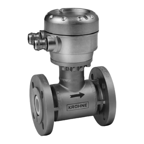
Electromagnetic flowmeter in flanged version
Hide thumbs
Also See for OPTIFLUX 5000:
- Handbook (40 pages) ,
- Quick start manual (24 pages) ,
- Supplementary instructions manual (40 pages)
Table of Contents
Advertisement
Quick Links
OPTIFLUX 5000
OPTIFLUX 5000
OPTIFLUX 5000
OPTIFLUX 5000
Electromagnetic flowmeter in flanged version
The documentation is only complete when used in combination with the relevant
documentation for the signal converter.
© KROHNE 07/2019 - 4005115503 - QS OPTIFLUX 5000 FL R06 en
Quick Start
Quick Start
Quick Start
Quick Start
Advertisement
Table of Contents

Related Manuals for KROHNE OPTIFLUX 5000


Summary of Contents for KROHNE OPTIFLUX 5000
- Page 1 Quick Start Quick Start Quick Start Electromagnetic flowmeter in flanged version The documentation is only complete when used in combination with the relevant documentation for the signal converter. © KROHNE 07/2019 - 4005115503 - QS OPTIFLUX 5000 FL R06 en...
-
Page 2: Table Of Contents
3.3 Virtual reference for IFC 300 (C, W and F version) ............17 3.4 Connection diagrams ..................... 17 4 Technical data 4.1 Dimensions and weights ....................18 5 Notes www.krohne.com 07/2019 - 4005115503 - QS OPTIFLUX 5000 FL R06 en... -
Page 3: Safety Instructions
If you need to return the device to the manufacturer or supplier, please fill out the form • contained in the manual and send it with the device. Unfortunately, the manufacturer cannot repair or inspect the device without the completed form. 07/2019 - 4005115503 - QS OPTIFLUX 5000 FL R06 en www.krohne.com... -
Page 4: Installation
5 Signal cable (remote versions only) INFORMATION! Assembly materials and tools are not part of the delivery. Use the assembly materials and tools in compliance with the applicable occupational health and safety directives. www.krohne.com 07/2019 - 4005115503 - QS OPTIFLUX 5000 FL R06 en... -
Page 5: Device Description
Product specific information and extensive product specification is available using PICK, the Product Information Center KROHNE web-tool. PICK can be found via the service menu button on the KROHNE.com website. The following versions are available: • Compact version (the signal is mounted directly on the flow ) •... -
Page 6: Nameplates (Examples)
• Store the device in a dry and dust-free location. • Avoid lasting direct exposure to the sun. • Store the device in its original packaging. • Storage temperature: -50...+70°C / -58...+158°F www.krohne.com 07/2019 - 4005115503 - QS OPTIFLUX 5000 FL R06 en... -
Page 7: Transport
• Allen key (4 mm) • Small screwdriver • Wrench for cable glands • Wrench for wall mounting bracket (remote version only) • Torque wrench for installing flowmeter in pipeline 07/2019 - 4005115503 - QS OPTIFLUX 5000 FL R06 en www.krohne.com... -
Page 8: General Requirements
Do not expose the signal to intense vibration. The flowmeters are tested for a vibration level • in accordance with IEC 60068-2-64. 2.7.1 Vibrations Figure 2-3: Avoid vibrations 2.7.2 Magnetic field Figure 2-4: Avoid magnetic field www.krohne.com 07/2019 - 4005115503 - QS OPTIFLUX 5000 FL R06 en... -
Page 9: Installation Conditions
INFORMATION! 2 dimensional bends occur in a vertical or or or or horizontal plane (X/Y) only, while 3 dimensional bends occur in both vertical and and horizontal plane (X/Y/Z). 07/2019 - 4005115503 - QS OPTIFLUX 5000 FL R06 en www.krohne.com... -
Page 10: T-Section
Figure 2-7: Distance behind a T-section 10 DN 2.8.4 Bends Figure 2-8: Installation in bending pipes (90°) Figure 2-9: Installation in bending pipes (45°) CAUTION! Avoid draining or partial filling of the flow www.krohne.com 07/2019 - 4005115503 - QS OPTIFLUX 5000 FL R06 en... -
Page 11: Open Discharge
Figure 2-10: Installation in front of an open discharge 2.8.6 Flange deviation CAUTION! Max. permissible deviation of pipe flange faces: 0.5 mm / 0.02" Figure 2-11: Flange deviation 2.8.7 Pump Figure 2-12: Installation behind a pump 07/2019 - 4005115503 - QS OPTIFLUX 5000 FL R06 en www.krohne.com... -
Page 12: Control Valve
Figure 2-13: Installation in front of a control valve 2.8.9 Air venting and vacuum forces Figure 2-14: Air venting 5 m / 17 ft 2 Air ventilation point Figure 2-15: Vacuum 5 m / 17 ft www.krohne.com 07/2019 - 4005115503 - QS OPTIFLUX 5000 FL R06 en... -
Page 13: Mounting Position
OPTIFLUX 5000 2.8.10 Mounting position Figure 2-16: Mounting position • Install flow sensor in line with the pipe axis. • Pipe flange faces must be parallel to each other. 07/2019 - 4005115503 - QS OPTIFLUX 5000 FL R06 en www.krohne.com... -
Page 14: Mounting
CAUTION! With the instrument, 4 PTFE gaskets are delivered (2 gaskets to be used with installation, 2 as spare). There are no other gaskets required. www.krohne.com 07/2019 - 4005115503 - QS OPTIFLUX 5000 FL R06 en... - Page 15 4 x ½" 150 / 300 4 x 5/8" 150 / 300 4 x 5/8" 8 x 5/8" 8 x ¾" 8 x ¾" 12 x 7/8" 12 x 7/8" 07/2019 - 4005115503 - QS OPTIFLUX 5000 FL R06 en www.krohne.com...
-
Page 16: Electrical Connections
Grounding can be omitted with Virtual reference (option on IFC 300). For detailed information refer to Virtual reference for IFC 300 (C, W and F version) on page 17 www.krohne.com 07/2019 - 4005115503 - QS OPTIFLUX 5000 FL R06 en... -
Page 17: Virtual Reference For Ifc 300 (C, W And F Version)
• Electrical conductivity: 200 μS/cm • Signal cable: max. 50 m / 164 ft, type DS 3.4 Connection diagrams INFORMATION! For the connection diagrams the documentation of the applicable signal converter. 07/2019 - 4005115503 - QS OPTIFLUX 5000 FL R06 en www.krohne.com... -
Page 18: Technical Data
IFC 100 (45°) ) ) ) IFC 100 (45 IFC 100 (45 IFC 100 (45 b = 161 mm / 6.3" c = 184 mm / 2.7" Total height = H + a www.krohne.com 07/2019 - 4005115503 - QS OPTIFLUX 5000 FL R06 en... - Page 19 = 157 mm / 6.18" c = 260 mm / 10.24" Total height = H + a 1 The value may vary depending on the used cable glands. 07/2019 - 4005115503 - QS OPTIFLUX 5000 FL R06 en www.krohne.com...
- Page 20 1 Sealing ring: PTFE (white) Optional: conductive PTFE (grey) / Gylon 3504 (blue) 2 Sealing ring for rounded counter flanges: filled PTFE (blue) 3 DN150...300 / 6...12"; optional spacer ring with gasket www.krohne.com 07/2019 - 4005115503 - QS OPTIFLUX 5000 FL R06 en...
- Page 21 A = + 0.8 / - 0.4 mm; + 0.031 / - 0.016 inches • B = + 0.5 / - 1.0 mm; + 0.02 / - 0.04 inches • 07/2019 - 4005115503 - QS OPTIFLUX 5000 FL R06 en www.krohne.com...
- Page 22 B = + 0.5 / - 1.0 mm; + 0.02 / - 0.04 inches • CAUTION! Pressures at 20 C / 68 • ° ° • For higher temperatures, the pressure and temperature ratings are as per ASME B16.5. www.krohne.com 07/2019 - 4005115503 - QS OPTIFLUX 5000 FL R06 en...
-
Page 23: Notes
NOTES OPTIFLUX 5000 07/2019 - 4005115503 - QS OPTIFLUX 5000 FL R06 en www.krohne.com... - Page 24 • Process Analysis • Services Head Office KROHNE Messtechnik GmbH Ludwig-Krohne-Str. 5 47058 Duisburg (Germany) Tel.: +49 203 301 0 Fax: +49 203 301 10389 info@krohne.com The current list of all KROHNE contacts and addresses can be found at: www.krohne.com...
Need help?
Do you have a question about the OPTIFLUX 5000 and is the answer not in the manual?
Questions and answers