Panduit Atlona OmniStream AT-OMNI-111-WP Manual
Wallplate networked av encoder
Hide thumbs
Also See for Atlona OmniStream AT-OMNI-111-WP:
- Manual (114 pages) ,
- Installation manual (8 pages) ,
- Solutions setup and configuration manual (61 pages)

Related Manuals for Panduit Atlona OmniStream AT-OMNI-111-WP


Summary of Contents for Panduit Atlona OmniStream AT-OMNI-111-WP
- Page 1 OmniStream ™ Wallplate Networked AV Encoder Atlona Manuals AT-OMNI-111-WP Networked AV...
- Page 2 Version Information Version Release Date Notes Sep 2019 Initial release AT-OMNI-111-WP...
- Page 3 Welcome to Atlona! Thank you for purchasing this Atlona product. We hope you enjoy it and will take a extra few moments to register your new purchase. Registration only takes a few minutes and protects this product against theft or loss. In addition, you will receive notifications of product updates and firmware.
- Page 4 Atlona, Inc. (“Atlona”) Limited Product Warranty Coverage Atlona warrants its products will substantially perform to their published specifications and will be free from defects in materials and workmanship under normal use, conditions and service. Under its Limited Product Warranty, Atlona, at its sole discretion, will either: •...
- Page 5 Atlona, Inc. (“Atlona”) Limited Product Warranty • Damage, deterioration or malfunction resulting from the installation or removal of this product from any installation, any unauthorized tampering with this product, any repairs attempted by anyone unauthorized by Atlona to make such repairs, or any other cause which does not relate directly to a defect in materials and/or workmanship of this product.
- Page 6 Important Safety Information 9. Do not defeat the safety purpose of a polarized CAUTION or grounding-type plug. A polarized plug has two RISK OF ELECTRIC SHOCK blades with one wider than the other. A grounding DO NOT OPEN type plug has two blades and a third grounding CAUTION: TO REDUCT THE RISK OF prong.
-
Page 7: Table Of Contents
Table of Contents Introduction Features Package Contents Panel Description Connection Instructions Connection Diagram Configuration Accessing Encoders in AMS Configuring a Static IP Address Input Selection Input Selection Verifying the Input Session Configuration Basic Operation LED Indicators Rebooting OmniStream Unicast Mode Multicast Mode 802.1X Authentication AES67 Audio... -
Page 8: Introduction
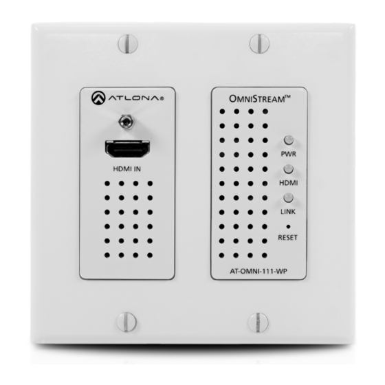
Introduction The Atlona OmniStream™ 111 Wallplate (AT-OMNI-111-WP) is a single-channel networked AV encoder for HDMI 2.0 sources up to 4K @ 60 Hz and HDR (High Dynamic Range), plus embedded audio. It features a US two-gang, Decora-style wallplate form factor, and includes interchangeable black and white wallplates and faceplates. The OmniStream 111 WP is part of the OmniStream Pro Series, designed for high performance, flexible distribution of AV over standard, off-the-shelf Gigabit Ethernet switches in commercial audiovisual applications. -
Page 9: Panel Description
Panel Description Front Side Rear TREAM HDMI IN HDMI LINK RESET RS-232 AT-OMNI-111-WP 1 HDMI IN 6 RESET Connect an HDMI cable from this port to an HD Press and release this button to reboot the AT- source. OMNI-111-WP. Note that this operation does not reset the unit to factory-default settings. -
Page 10: Connection Instructions
Installation Connection Instructions IMPORTANT: The venting holes, surrounding the enclosure, along with the fan assembly on the back of the unit, provides cooling by expelling warm air from the enclosure. To prevent overheating, make sure these holes and the fan assembly are not blocked. 1. -
Page 11: Connection Diagram
Installation Connection Diagram Camera I-1 11 -O MN RE SE TR EA M NI Laptop AT-OMNI-111-WP AT-OMNI-112 Media Player AT-OMNI-122 Display AT-OMNI-121 AT-OMNI-122 Display Display Display Display AT-OMNI-111-WP... -
Page 12: Configuration
Configuration Accessing Encoders in AMS It is recommended that the Atlona Management System (AMS) be used to configure and control OmniStream devices. AMS uses multicast Domain Name Server (mDNS) to automatically discover each encoder on the network. AMS is free and can be downloaded from https://www.atlona.com/ams. By default, encoders are set to DHCP mode, allowing a DHCP server (if present) to assign the encoder an IP address. - Page 13 Configuration 6. Click Devices from the fly-out menu. 7. Click the Unassigned option. 8. If the device isn’t immediately listed, click the left and right arrows, at the bottom of the Unassigned list, to scroll through all available devices. Arrow buttons AT-OMNI-111-WP...
- Page 14 Configuration All available encoders will be displayed under the Unassigned category. When an encoder is unassigned, it means that it has not been assigned to a site, building, and/or room. Refer to the AMS User Manual for more information on these topics. If a DHCP server is not found within 60 seconds, the encoder will be placed in Auto IP mode and assigned an IP address within the range of 169.254.xxx.xxx.
- Page 15 Configuration 11. Click SESSION in the top menu bar. 12. Locate the Video section. 13. Delete the value in the Destination Multicast / Unicast Address field. Destination Multicast/Unicast Address field 14. Locate the Audio section and delete the value in the Destination Multicast / Unicast Address field. Destination Multicast/Unicast Address field SAVE button 15.
-
Page 16: Configuring A Static Ip Address
Configuration Configuring a Static IP Address The following section is only required to when setting an encoder to a static IP address. If a DHCP server is not found within 60 seconds, encoders are automatically placed in Auto IP mode and will be assigned an IP address within the range 169.254.xxx.xxx. -
Page 17: Input Selection
Configuration Input Selection Once the OmniStream encoder is configured, and can be located on the network, the encoder will need to be instructed on how to handle source devices and to which stream each source is assigned. Input Selection 1. Under AMS, click INPUT in the menu bar. 2. -
Page 18: Verifying The Input
Configuration Verifying the Input 1. Click INPUT in the menu bar. Cable Present indicator 2. Check the Cable Present indicator. If a cable is connected from a source to an input on the encoder, then the indicator will be green. If no cable is connected, then the indicator will be red. Note that this indicator may also reflect the integrity of the cable: if the cable is bad or does not maintain a secure connection, then the Cable Present indicator may also be displayed as red. -
Page 19: Session Configuration
Configuration Session Configuration Once the inputs have been assigned to the desired source, the next step is to configure each session. A session is a class-D multicast IP address that is assigned to an AV stream. If each stream is configured for bit rates less than 450 Mbps (only recommended for 1080p and lower resolutions), a single Ethernet cable can transport two sessions. -
Page 20: Basic Operation
Basic Operation LED Indicators The following table provides a listing of front-panel LED indicators and their status: Description • If using a PoE switch, make sure that the port on the switch that is connected to the encoder, has PoE enabled. When the encoder is powered using PoE, the PWR indicator will be green. -
Page 21: Rebooting Omnistream
Basic Operation Rebooting OmniStream To reboot the OmniStream encoder, press and release the recessed button, on the far-right side of the unit, using a small, pointed object. Rebooting the encoder does not reset the encoder to factory-default settings. TREAM HDMI IN HDMI LINK RESET... -
Page 22: Unicast Mode
Basic Operation Unicast Mode The term unicast is used to describe a configuration where information is sent from an encoder to a single decoder. Although it is common to have multiple encoder and decoder units within a system, it may also be desirable to restrict a single encoder to communicate with one decoder. - Page 23 Basic Operation 5. Go to the decoder AMS interface. Refer to the OmniStream Single-Channel / Dual Channel A/V Decoder User Manual, if necessary. 6. Click IP INPUT from the menu. 7. Remove the IP address from the Multicast Address field. 8.
-
Page 24: Multicast Mode
Basic Operation Multicast Mode The term multicast is used to describe a configuration where information is sent from one or more points to a set of other points. For example, a single encoder can transmit data to multiple decoders. In addition, if multiple encoders are used, each encoder can stream data to any decoder that is not already receiving data from an encoder. - Page 25 Basic Operation AT-OMNI-111-WP...
-
Page 26: 802.1X Authentication
Advanced Operation 802.1X Authentication 802.1X is a server-based port authentication which restricts unauthorized (rogue) clients from connecting to a Local Area Network through a public port. In its simplest form, 802.1X usually involves three parties: supplicant (client device), authenticator (Ethernet switch or WAP), and an authentication server. Before the device is permitted on the network, port communication is restricted to Extensible Authentication Protocol over LAN (EAPOL) traffic. - Page 27 Advanced Operation 1. Login to AMS. Refer to Accessing Encoders in AMS (page 12), if necessary. 2. Click Devices > All and select the desired encoder from the Device List. 3. Click NETWORK in the menu bar. 4. Click the SHOW ADVANCED button to expand the options under both Network window groups. 5.
- Page 28 Advanced Operation 8. Refer to the table below for a list of available authentication methods. An orange dot indicates that this field will be displayed as part of the method. Authentication Method Identity Password CA Certificate CA Certificate Client Private Certificate PEAP/MSCHAPv2 EAP-TLS...
-
Page 29: Aes67 Audio
Advanced Operation AES67 Audio AES67 audio is a standard for high-performance audio streaming over IP, providing several features such as synchronization, media clock identification, and connection management. AES67 does not support compressed audio formats, such as Dolby® Digital, and others. Source audio must be transmitted as LPCM 2.0 or 5.1. 1. -
Page 30: Edid Management
Advanced Operation EDID Management OmniStream encoders provide EDID management for each input. The encoder can be assigned one of several included EDID presets or can be assigned a custom EDID. Raw EDID data can be copied from displays or other sink devices, that are connected to OmniStream decoders. - Page 31 Advanced Operation 6. Enter the EDID data in the Raw EDID field. EDID data can be copy and pasted from an EDID editor and must be in hexadecimal format. Commas or spaces can be included as delimiters to separate each hexadecimal value. 7.
-
Page 32: Copying An Edid From The Display
Advanced Operation Video mode only EDID Dolby Dolby DTS-HD Dolby LPCM LPCM Digital* MA † True HD* Default -Video Mode Default - Video Mode (No HDR) 4K60 MCH 4K60 PCM-MCH 460 LPCM 2CH 720P DD 720P 2CH * Dolby Atmos® is carried with either Dolby Digital Plus or Dolby True HD audio streams. DTS:X is carried with DTS-HD MA audio streams. - Page 33 Advanced Operation 4. Locate the EDID section. This is the EDID of the display which is connected to the decoder. Click and select the data in this field, then press [CTRL]+[C] to copy the data. Display’s EDID 5. Select the desired encoder, within AMS. 6.
- Page 34 Advanced Operation 9. Enter the name of the EDID in the EDID Name field. Spaces and special character are valid entries. Use a descriptive name for this field. 10. Paste the EDID data into the Raw EDID field by pressing [CTRL]+[V]. 11.
-
Page 35: Encoder Grouping
Advanced Operation Encoder Grouping Grouping encoders allows a group of encoders to feed a single decoder, simultaneously. The stream will be displayed by the decoder using either manual or automatic input-selection, based on the presence of a source signal. 1. Login to AMS. Refer to Accessing Encoders in AMS (page 12), if necessary. - Page 36 Advanced Operation 9. Click the Enable Encoder Group toggle switch to enable encoder grouping. When enabled, this toggle switch will be green. 10. Click the Trigger drop-down list and select the desired trigger mode. Enable Encoder Group Mode Description manual Use this setting to manually enable the input.
-
Page 37: Scrambling
Advanced Operation Scrambling OmniStream supports 128-bit Advanced Encryption Standard (AES) scrambling for both audio and video streams. Scrambling can be enabled or disabled through AMS, and can be individually applied to video, audio, or both. Scrambling can be enabled either before or after the decoding process is started. Data streams cannot be scrambled. -
Page 38: Using The Virtual Matrix
Advanced Operation Using the Virtual Matrix 1. Access the Virtual Matrix. Refer to The Virtual Matrix (page 60) for more information. 2. Locate the desired encoder or decoder. Scrambling is managed on the encoder; descrambling is managed on the decoder. 3. -
Page 39: Setting The Video Mode
Advanced Operation Setting the Video Mode OmniStream offers two video modes: Video and PC application. These two modes will optimize the video, based on the type of information that is being displayed. Use the Video mode when display motion graphics/video. Set this mode to PC application when viewing static images, such as spreadsheets or similar content. -
Page 40: Slate / Logo Insertion
Advanced Operation Slate / Logo Insertion Slate / logo insertion is managed from within AMS. The difference between a “slate” and “logo” is in the size of the image and how it is used: Logos are classified as smaller, low-resolution images that can be positioned at specified locations on the screen. - Page 41 Advanced Operation Image window group 8. Perform one of the following: • If the selected image will be used as a logo, then proceed with Steps 9 through 13. • If the image will be used as a slate, skip to Step 14. 9.
- Page 42 Advanced Operation 10. Click the Aspect Ratio drop-down list to set the aspect ratio of the image. Selecting Keep will maintain the aspect ratio. Select Stretch to scale the image to fill the screen. 11. Enter the location of the on-screen image, in pixel values, by entering the desired values in the Horizontal and Vertical fields.
-
Page 43: Deleting Slates / Logos
Advanced Operation Deleting Slates / Logos Follow the instructions below to remove a logo/slate image. 1. Click OTHER in the menu bar. 2. Click the DELETE button in the desired image window group. When the DELETE button is clicked, the window group and the associated image will be deleted from the encoder. -
Page 44: Text Insertion
Advanced Operation Text Insertion 1. Login to AMS. Refer to Accessing Encoders in AMS (page 12), if necessary. 2. Click OTHER in the menu bar. 3. Click Text in the side menu bar, in the upper-left corner of the AMS screen. 4. -
Page 45: The Ams Interface
The AMS Interface Device Info page The Device Info page provides general information about the encoder. Alias Enter a name for the unit in this field. This is optional. Model The model number of the unit. The OmniStream Wallplate will use the name AT-OMNI-111-WP. IP Address Displays the IP address of the encoder. - Page 46 The AMS Interface Hostname The hostname of this unit. This can be changed if desired. By default, the host name is automatically created using the model of the unit and adding the last five digits of the unit serial number. FACTORY RESET Click this button to reset the encoder to factory-default settings.
-
Page 47: Input Page
The AMS Interface Input page The Input page provides signal information for each channel (input). If using the single-channel encoder, only a single (input) channel will be displayed. Input The selected input. This value can be HDMI Input 1, Video Generator 1, or None. Bit Rate The current video bit rate. - Page 48 The AMS Interface EDID Click the drop-down list to select the desired EDID. Refer to the table elow for a list of available EDID selections. EDID Description Default Default OmniStream EDID ATL 1080P 2CH 1920x1080p60 with two-channel PCM audio ATL 1080P DD 1920x1080p60 with Dolby Digital audio ATL 1080P DVI 1920x1080p60 with video formatted as DVI...
- Page 49 The AMS Interface Advanced Settings Click the SHOW ADVANCED button to view the following options. Slate Mode Click this drop-down list to enable slate mode or select the desired slate to be used. Refer to Slate / Logo Insertion (page 40) for more information.
-
Page 50: Serial Page
The AMS Interface Serial page IMPORTANT: The AT-OMNI-111-WP does not currently support serial (RS-232) functionality. However, the page is listed within AMS. AT-OMNI-111-WP... -
Page 51: Session Page
The AMS Interface Session page The Session page provides the ability to configure all session parameters. Up to two sessions are supported on the AT-OMNI-111-WP. Interface Click this drop-down list to select the desired interface. Interface Description eth1 ETHERNET 1 port Not Used Ethernet interface is disabled Click this switch to enable to disable the Session Announcement Protocol. - Page 52 The AMS Interface Encoder Click this drop-down list to select the desired HDMI input. Enable Video Click the toggle switch to enable or disable the video stream. When enabled, the toggle switch will be green. By default, video streaming is enabled. Disabling the video stream can be used to “mask” the video on the decoder endpoints.
- Page 53 The AMS Interface Advanced Settings Click the SHOW ADVANCED button to view the following options. DSCP, FEC Enable, FEC Rows, and FEC Columns apply to both Video and Audio sections. DSCP Select the Differentiated Services Code Point (DSCP) type from the DSCP drop-down list. This value will be used to determine the Quality of Service (QoS) on a network.
-
Page 54: Network Page
The AMS Interface Network page The Network page provides the ability to enable or disable DHCP mode for each video channel. When DHCP mode is disabled, the IP address, subnet mask, and gateway must be provided. This screen is identical to the Network page for the decoder. - Page 55 The AMS Interface Advanced Settings Click the SHOW ADVANCED button to view the following options. Link Speed Displays the port speed in Mbps. MAC Address The MAC address of the Ethernet channel. Telnet Authentication Click this toggle switch to enable or disable Telnet authentication. If enabled, then the toggle switch will be green. Once enbled, connecting to the encoder using Telnet will require login credentials.
-
Page 56: Other Page
The AMS Interface Other page The Other page provides logo/slate, text, and PTP management. Click the menu in the upper-left corner of the AMS screen to switch between Logo, Text, and PTP screens. Logo The Logo page provides the ability to upload a custom logo. This logo will be displayed when no video signal is detected. -
Page 57: Text
The AMS Interface Vertical Enter the vertical position of the logo on the screen. Height Enter the horizontal resolution of the logo, in pixels. Width Enter the vertical resolution of the logo, in pixels. IMPORTANT: Maximum logo resolution (both height and width) is 1/4 of the video resolution. Text The Text page provides the ability to display scrolling or stationary text superimposed on the source image. -
Page 58: Ptp
The AMS Interface Horizontal (%), Vertical (%) Specify the location of the text in the Horizontal (%) and Vertical (%) fields. Each of these values is based on the horizontal and vertical resolution of the screen. Width (%), Height (%) Specify the size of the text in the Width (%) and Height (%) fields. - Page 59 The AMS Interface Domain Number Enter the domain number in this field. Valid entries are 0 through 127. Priority 1 Enter the priority number in this field. Priority 2 Enter the priority number in this field. Is GM Present This indicator displays the existence of a grandmaster clock for the specified PTP domain number. If the indicator is green, then the grandmaster clock exists on this interface.
-
Page 60: The Virtual Matrix
The AMS Interface The Virtual Matrix 1. Login to AMS. Refer to Accessing Encoders in AMS (page 12), if necessary. 2. Click the icon, in the upper-left corner of the AMS Dashboard. 3. Click Virtual Matrix. 4. The OmniStream Virtual Matrix page will be displayed. AT-OMNI-111-WP... -
Page 61: Layout And Operation
The AMS Interface Layout and Operation The illustration below, shows a multiple OmniStream units (encoders and decoders). The Virtual Matrix is organized into rows and columns. The blue circle with the checkmark indicates that these two OmniStream units are connected to one another. The second column identifies a dual-channel decoder (AT-OMNI-122). - Page 62 The AMS Interface When these icons are clicked, the associated icons will be displayed in the rows and columns of the Virtual Matrix. Symbol Description Video only Audio only Data only Connected; not all signals are active Connected; all streams are being used Video stream Audio stream Data stream...
-
Page 63: Appendix
Appendix Updating the Firmware IMPORTANT: • If updating from version 1.0.x, OmniStream units must first be updated to version 1.1. Note that this does not apply to OmniStream R-Type units. If running version 1.0.x, contact an Atlona Technical Support Engineer before updating the firmware. •... - Page 64 Appendix 5. After the UPDATE FIRMWARE button is clicked, the Upgrade Firmware Started message box will be displayed. 6. Click the orange up-arrow icon, in the upper-right corner of the screen, as shown below. If this icon is orange, it indicates that a firmware update is in progress. The progress bar for the update process will be displayed.
-
Page 65: Fec Details
Appendix FEC Details Matrix Size, Overhead, and Latency • FEC can only work if a single packet from each row/column is missing. Multiple packets missing from each row/ column will cause FEC to fail. • Due to the above, a smaller matrix is more robust, as there is a better chance of errors not occurring in the same row/column. -
Page 66: Fec, Latency, And Lip Sync
Appendix FEC, Latency, and Lip Sync • In order for FEC to work, the matrix must be filled in order to calculate the FEC packets. This introduces some additional latency. Due to high bitrates, this is not noticeable for video, but can be very significant for audio. Therefore, Atlona recommends either leaving FEC disabled for audio or using a very small matrix. -
Page 67: Specifications
Appendix Specifications Video HDMI Specification HDMI 2.0b, HDCP 2.2 UHD/HD/SD 4096×2160 (DCI) @ 60 /30/24 Hz 720x576p @ 50 Hz 3840×2160 (UHD) @ 60 /50/24/25/30 Hz 720x576i @ 25 Hz 1920x1080p @ 23.98/24/25/29.97/30/50/59.94/60 Hz 720x480p @ 59.94/60 Hz 1920x1080i @ 25/29.97/30 Hz 720x480i @ 29.97/30 Hz 1280x720p @ 30/50/59.94/60 Hz VESA... - Page 68 Appendix Protocols Video Streaming Audio Streaming RTP, up to 7.1 channels AES67, up to LPCM 7.1 channels Addressing DHCP, static Encryption AES-128 QoS Tagging RFC 2475 Discovery Multicast DNS, LLDP, SAP Management HTTPS, SSH, Telnet, and WebSockets with TLS Authentication IEEE 802.1x: PEAP/MSCHAPv2 or EAP-TLS IP Multicast IGMPv2 and IGMPv3 support...
- Page 69 Toll free US International atlona.com 877.536.3976 41.43.508.4321 • • © 2020 Atlona Inc. All rights reserved. “Atlona” and the Atlona logo are registered trademarks of Atlona Inc. All other brand names and trademarks or registered trademarks are the property of their respective owners. Pricing, specifications and availability subject to change without notice.
Need help?
Do you have a question about the Atlona OmniStream AT-OMNI-111-WP and is the answer not in the manual?
Questions and answers