Table of Contents
Advertisement
Quick Links
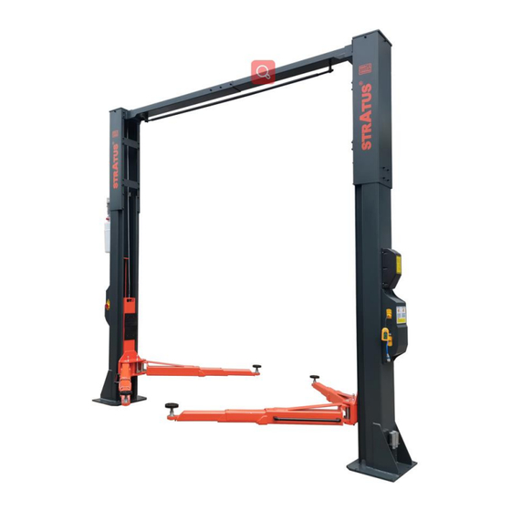
Model No. SAE-C12XE
Direct drive 2 post Lift
Single point electric release
Lifting Capacity 12,000 lbs
mportant Note
I
1.
This equipment can not be installed, operated or repaired without reading instructions.
2.
Electricity must be hooked up by certified electrician.
3.
Do not use this equipment beyond its rated capacity.
Installation & Operation &
Maintenance Instructions
1
Advertisement
Table of Contents

Related Manuals for Stratus SAE-C12XE


Summary of Contents for Stratus SAE-C12XE
- Page 1 Model No. SAE-C12XE Installation & Operation & Maintenance Instructions Direct drive 2 post Lift Single point electric release Lifting Capacity 12,000 lbs mportant Note This equipment can not be installed, operated or repaired without reading instructions. Electricity must be hooked up by certified electrician.
-
Page 2: Table Of Contents
TABLE OF CONTENTS Packing, transport and storage ............................3 Packing ................................. 3 Transport ................................3 Storage .................................. 4 Technical specifications ..............................5 Equipment plan ..............................6 Safety .................................... 7 Important notices ..............................7 Qualified personnel ............................. 7 Danger notices ..............................7 Training ................................ -
Page 3: Packing, Transport And Storage
Operation and use ................................18 Controls ................................18 Vehicle positioning ............................18 Lifting .................................. 18 Standing ................................19 Lowering ................................19 Install limit switch ............................. 19 Install the limiter switch inside of the main column ..................19 Connect the limiter switch connector to the motor ..................19 Maintenance ................................ -
Page 4: Storage
the carrier must be immediately informed. The machine is heavy goods! Don’t take manpower load and unload and transporting way into consideration, the ➢ safety of working is important. ➢ Furthermore, during loading and unloading operation goods must be handled as shown in the picture. Storage The machine equipment should be stocked in the warehouse, if stocked outside should do the disposal well of ➢... -
Page 5: Technical Specifications
Technical specifications Machine model SAE-C12XE Lifting capacity 12,000lbs (5,500kg) Lifting Height 83.07"(2110MM) Minimum height 3.94"(100M) Lifting time About 50 sec Voltage 220V Frequency 60Hz power 2.2KW/3HP Hydraulic oil 46#/68# Working temperature 41° F - 104° F ambient humidity 30-95% Machine noise <... -
Page 6: Equipment Plan
Equipment plan... -
Page 7: Safety
Safety Important notices This ultra thin low lift is specially designed for lifting motor vehicles that weighs within its outmost lifting capacity. ➢ Users are not allowed to use it for any other purposes. Otherwise, we, as well as our sales agency, will not bear any responsibility for accidents or damages of the lift. -
Page 8: Training
Training Only these qualified people, who have been properly trained, can operate the lift. We are quite willing to provide ➢ professional training for the users when necessary. ➢ Attention: For environment protection, please dispose the disused oil in a proper way. Warning signs All safety warning signs attached on the machine are for the purpose of drawing the user’s attention to safety ➢... -
Page 9: Installation
Installation Only skilled technicians, appointed by the manufacturer, or by authorized dealers, must be allowed to carry out ➢ installation. Serious damage to people and to the lift can be caused if installations are made by unskilled personnel ➢ Always refer to the exploded views attached during installation. Tool required Rotary Hammer Drill D.20 Carpenter’s Chalk... -
Page 10: Checking For Room Suitability
Checking for room suitability The lift has been designed to be used in covered and sheltered places free of overhead obstructions. ➢ The place of installation must not be next to washing areas, painting workbenches, solvent or varnish deposits. The ➢... -
Page 11: Assembly Diagram
Assembly diagram Assemble columns Assemble main column & extension column, and then stand up the 2 columns (the column with the power unit base ➢ plate is the main column and the other one is the vice column) Note: Don't drill anchor bolts holes or install anchor bolts now. ➢... - Page 12 2. Install the overhead beam cable pulley Warning: Symmetrical installation and asymmetrical installation of the cable pulley positions are not universal. In-correct installation of the pulley positions may cause damage to the cable or the lift. 2.1.For symmetrical installation, use the long shaft and the long shaft sleeve to fix the cable pulley (pre-installed) . Note: During the installation, the positions of the cable pulley at both ends of the overhead beam should be installed correspondingly.
-
Page 13: Position Columns
Position columns ➢ Check if the columns are vertical to the ground with level, insert thin shims (come with package) to adjust when necessary Symmetric installation Adjust carriage 4.10 Raise the carriage to the 1st locking position located at the bottom of the column . ➢... -
Page 14: Install Cables (2 Cables In Total )
Install cables (2 Cables in total ) 4.11 Symmetric Installation Cable Routing Asymmetric Installation Cable Routing Routing the safety release cable 4.12 The safety lock has been pre-installed. Install safety lock release cable to connect the safety lock on the main column and vice column. Install safety lock cover. -
Page 15: Installation Of Power Unit
Installation of power unit 4.13 Attach the power unit onto the bracket ; Secure it using nuts M10X20, the locking washers D.10 and washers D. Mount the bracket with the power unit on the column with screw M8X16 Connection of hydraulic hoses 4.14 Connect the longer hose in between the 2 cylinders, connect the short hose in between the cylinder and the power unit. -
Page 16: Oil Filling And Bleeding
Oil filling and bleeding 4.16 DO NOT run power unit without oil. Damage to pump can occur. If motor gets hot or sounds peculiar, stop immediately and recheck the electric connection. If the vented cap is lost or broken, order the replacement. The oil tank must be vented well. Add about 2.5 gallons of hydraulic oil to the hydraulic fluid reservoir, AW32 during winter time (cold weather), and AW46 during summer time (hot weather). -
Page 17: Check Before Start-Up
Check before start-up General checks Make sure that the columns are plumb; Make sure the lift anchored to the ground and all anchor bolts tightened. Make sure the electrical system feeding voltage is equal to that specified in the nameplate on the motor; Make sure the electric system connection in conformity of the electric plan shown as the electric diagram and for proper grounding. -
Page 18: Operation And Use
Operation and use NEVER operate the lift with any person or equipment below. NEVER exceed the rate lifting capacity. NEVER lift a vehicle in any manner with less than four arms. Always ensure that the mechanical locks are engaged before any attempt is made to work on or near the vehicle. Always lift a vehicle on the lifting pads. -
Page 19: Standing
Standing Press the lowering lever to engage the nearest lock position; Always ensure that the lock in each column is engaged before any attempt is made to work on or near the vehicle. Lowering Raise the lift a little bit by pushing the lifting button to clear off the mechanical locks; Release the locks manually;... -
Page 20: Maintenance
Maintenance Only trained people who know how the lift works, can be allowed to service the lift. To service properly the lift, the following has to be carried out: use only genuine spare parts as well as equipment suitable for the work required; follow the scheduled maintenance and check periods shown in the manual;... -
Page 21: Troubleshooting
Troubleshooting Troubleshooting and possible maintenance require all safety precautions specified in the absolute instructions. Problem Possible cause Solution The lift does non rise Burnt fuse Replace fuse Connect again when the pushbutton is Line current does not arrive Malfunction pressed Call Service Center in the electric plant: (motor does not run) -
Page 22: Parts List
Parts list Main column and parts list... -
Page 24: Packing List
Packing list... -
Page 25: Special Notes
Special notes Environmental damage 10.1 Only appropriately trained personnel may dismantle and dispose of the unit. Dismantling 10.2 To dismantle the product, proceed as follows: ELECTRICAL HAZARD! When carrying out any decommissioning and dismantling work on the unit, switch off all power supply connections, ensure they cannot be switched on unintentionally and verify that they have been disconnected.
Need help?
Do you have a question about the SAE-C12XE and is the answer not in the manual?
Questions and answers