Table of Contents
Advertisement
Quick Links
Advertisement
Table of Contents

Related Manuals for Stratus SAE-P410


Summary of Contents for Stratus SAE-P410
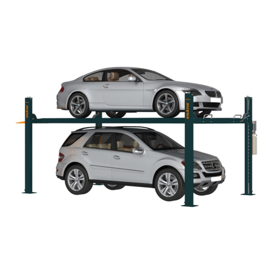
- Page 1 SAE-P410 Installation, Operation Four Post Parking Lift and Parts Manual Manual Release Maximal Capacity:10000 lbs. Distributed by Please read this entire manual carefully and completely before installation or operation of the lift. 22/02/2022 http://stratusautoequip.com...
-
Page 2: Table Of Contents
Installation, Operation and Parts Manual SAE-P410 SAFETY ..................................3 1.1 Operation of lifting platforms .............................. 3 1.2 Checking of the lifting platforms ............................3 1.3 Important safety notices ..............................4 1.4 Risks and safety instructions ..............................5 PACKING AND TRANSPORTATION..........................6 2.1 Packing .................................... -
Page 3: Safety
Installation, Operation and Parts Manual SAE-P410 SAFETY 1.1 Operation of lifting platforms This lift is specially designed for vehicle parking. Users are not allowed to use it for any other purposes. The applicable national regulations, laws and directives must be observed. -
Page 4: Important Safety Notices
Installation, Operation and Parts Manual SAE-P410 to be able to check and give an expert option on lifting platforms. 1.3 Important safety notices 1.3.1 Recommend for indoor use only. DO not expose the lift to rain, snow or excessive moisture. -
Page 5: Risks And Safety Instructions
Installation, Operation and Parts Manual SAE-P410 1.4 Risks and safety instructions During lift functioning, the operator shall stand in a safe area. The presence of persons beneath the cross-pieces and/or the platforms when they are moving, or the presence of persons inside the danger zone is strictly prohibited. -
Page 6: Packing And Transportation
Installation, Operation and Parts Manual SAE-P410 PACKING AND TRANSPORTATION Packing, lifting, handling, transporting operations must be performed only by experienced personnel with appropriate knowledge of the lift and after reading this manual. 2.1 Packing The lift is shipped with two parts... -
Page 7: Products Descriptions
Installation, Operation and Parts Manual SAE-P410 PRODUCTS DESCRIPTIONS 3.1 General descriptions This four post lift is generally composed by four posts, two beams, two platforms, a hydraulic oil cylinder and a set of power unit. It is driven by an electro-hydraulic system. Up and down of platforms is controlled by the to and fro movement of the oil cylinder. It is equipped with mechanical safety locks in the four posts, which is to prevent the platforms from sudden dropping down in case the hydraulic system fails to work. -
Page 8: Dimensions
Installation, Operation and Parts Manual SAE-P410 3.3 Dimensions... -
Page 9: Technical Data
Installation, Operation and Parts Manual SAE-P410 3.4 Technical data Power type Electro-hydraulic Maximal Capacity 10000 lbs. Full rise height 77-9/16” Initial height 5-1/2” Full rise time ≤70S Full descending time ≤60S Working pressure ≥2900PSI. Power supply 110V-1PH-60HZ Motor capacity 2.2kW Oil tank volume 3.17 us gal... - Page 10 Installation, Operation and Parts Manual SAE-P410 Newly built concrete ground must be older than 20days. 4.1.4 Tools and equipment needed for installation Tool name Specification Quantity Open spanner D17-19, D22-24 Hex socket spanner D2.5-14 Adjustable spanner Above D30 Cross socket screw driver...
-
Page 11: Installation Attentions
Installation, Operation and Parts Manual SAE-P410 4.2 Installation attentions 4.2.1 Joints of oil hose and wiring must be firmly connected in order to avoid leakage of oil hose and looseness of electrical wires. 4.2.2 All bolts should be firmly screwed up. - Page 12 Installation, Operation and Parts Manual SAE-P410 Step 3: Use the forklift to have the general parts properly positioned. For convenient installation, it would be better to pad something supporting under the platform. Oil cylinder, steel cable and oil hose have already been fixed in the power side platform (platform with oil cylinder beneath) before packing.
- Page 13 Installation, Operation and Parts Manual SAE-P410 Step 5: Mount on the top post plate and fix safety ratchets. 1. Fix ratchet with the top post plate with M20 hex nut and flat washer. Ensue the four safety ratchets are of the same height from the ground, This could be checked by measuring the distance of the lowest square hole reserved on the ratchet and the floor.
- Page 14 Installation, Operation and Parts Manual SAE-P410 2. Lift the platform with proper lifting equipment and place it onto the crossbeams. Fix the lifting platform and the crossbeam with M12*25 hex socket flat head screw. ① Hex socket flat head screw M12*25...
- Page 15 Installation, Operation and Parts Manual SAE-P410 3. Fix the installation plate for drive-on ramps ① Installation plate for drive-on ramp ② M16*25 hex head screw ③ Flat washer Step 7: Fix transfer bar. Insert the two section of the transfer bar respectively to the swing shaft assemblies in both crossbeams. Connect the two sections into a whole with screws.
- Page 16 Installation, Operation and Parts Manual SAE-P410 Step 8: Fix steel cables and relevant accessories. 1. Route and fix steel cables; 2. Fix crossbeam protective covers; 3. Install release handle; ① steel cable; ②M20 hex nut; ③20 flat washer; ④M20 hex nut; ⑤ Protective cover; ⑥8*12 hex socket button head screw;...
- Page 17 Installation, Operation and Parts Manual SAE-P410 Step 9: Connect hydraulic hoses and electrical wires. Refer to electrical and hydraulic connection diagrams before making connection. Refer to Annex 1 when fix the hydraulic system. Attention: Connect oil hoses as per the marks on the hoses and do not contaminate the hydraulic components during the connection.
-
Page 18: Items To Be Checked After Installation
Installation, Operation and Parts Manual SAE-P410 2. Secondly, level the platforms after mechanical safety locks are engaged. Raise the platform about 31” high and push the unloading handle to engage the mechanical safety lock. Judge if the mechanical locks could be engaged synchronously by listening to the sound. -
Page 19: Operation Instructions
Installation, Operation and Parts Manual SAE-P410 OPERATION INSTRUCTIONS 5.1 Precautions 5.1.1 Check all connections of oil hose. Only when there is no leakage, the lift can start work. 5.1.2 The lift, if its safety device malfunctions, shall not be used. -
Page 20: Annex 1, Hydraulic Schemes And Parts List
Installation, Operation and Parts Manual SAE-P410 Annex 1, Hydraulic schemes and parts list 1.Oil tank 2.Oil sucking filter 3.Gear pump 4.Coupling 5.Motor 6.Composite hydraulic block 7.Cushion valve 8.Over-flow valve 9.Single way valve 10.Manual unloading valve 11.Throttle valve 12.Oil tank cover 13.Hydraulic cylinder... - Page 21 Installation, Operation and Parts Manual SAE-P410 POS. Code Name Specification 330405030 Oil tank 330101004 Composite hydraulic block YF-2 330304001 Overflow valve EYF-C 330302001 Single way valve DYF-C...
- Page 22 Installation, Operation and Parts Manual SAE-P410 POS. Code Name Specification 330305002 Throttle valve 207103019 Composite washer 330301001 Cushion valve HZYF-C1 202109064 Hex socket cylinder head screw M6*30 330201006B Gear pump CBK-F225/CBK-2.5F 310101003 Straight connector M14*1.5,-G1/4 330404001 Coupling YL-A 330401009 Oil sucking tube...
-
Page 23: Annex 2, Electrical Schemes And Parts List
Installation, Operation and Parts Manual SAE-P410 Annex 2, Electrical schemes and parts list POS. Code Name Specification 110V-2.2KW -1PH-60H2-4P 320201082 Motor 220V-2.2KW-1PH-60HZ-2P 320201066 Motor NP2-EA11(LAY5S-EA11) 320401042 Button 320901014 AC contactor (110V) CJX2-1210/AC110 320901003 AC contactor (220V) CJX2-1210/AC220... -
Page 24: Annex 3, Mechanical Exploded Drawings And Parts List
Installation, Operation and Parts Manual SAE-P410 Annex 3, Mechanical exploded drawings and parts list POS. Code Description Specification 614032071 Power side post 6445P-A1-B1 614032072 Post 6445P-A1-B2 614032073 Top post plate 6445P-A1-B3 612032074 Safety ratchet 6445P-A1-B4... - Page 25 Installation, Operation and Parts Manual SAE-P410 POS. Code Description Specification 202110005 Hex socket button head screw M8*20 615032065 Steel cable 6445P-A3-B8 203101012 Hex nut 204101011 Flat washer C 201102026 Hex head full swivel screw M12*25 204201006 Spring washer 204101007 Flat washer C...
- Page 26 Installation, Operation and Parts Manual SAE-P410...
- Page 27 Installation, Operation and Parts Manual SAE-P410...
- Page 28 Installation, Operation and Parts Manual SAE-P410 POS. Code Description Specification 614032080 Power side crossbeam 6445P-A7-B1 420320060 Slider 6445P-A7-B17 202109044 Hex socket cylinder head screw M10*35 204101006 Flat washer C 202109075 Hex head full swivel screw M10*80 202110004 Hex socket button head screw...
- Page 29 Installation, Operation and Parts Manual SAE-P410 POS. Code Description Specification 203103005 Hex locking nut 612032082 Release plate A 6445P-A7-B6 612032083 Release Plate B 6445P-A7-B7 612032042 Main swing rod 64P-A7-B3 206201001 Cotter pin M2.5*30 410321691 Torsional spring 64P-A7-B19 204301004 Circlip 612030003...
- Page 30 Installation, Operation and Parts Manual SAE-P410 POS. Code Description Specification 614032078 Main platform 6445P-A5-B1 614032079 Secondary platform 6445P-A5-B2 410322721 Pulley A 6445P-A7-B12 205101069B Bearing 6435B-A4-B13 410322761 Double slots pulley 6445P-A7-B16 205101102 Bearing 40*50*34 410278751 6435B-A4-B34 φ40 large flat washer(42*75*2) 202109057...
- Page 31 Installation, Operation and Parts Manual SAE-P410 POS. Code Description Specification 202110005 Hex socket button head screw M8*20 204101005 Flat washer C 420270240 Guiding slider 6435B-A4-B23 202111007 Hex socket flat head screw M8*20 202111015 Hex socket flat head screw M12*25 410322813...
Need help?
Do you have a question about the SAE-P410 and is the answer not in the manual?
Questions and answers