Table of Contents
Advertisement
Quick Links
Stratus
Model No.: SAE-F14X
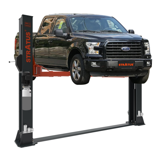
2 Post Base Plate Lift
Single (1) Point Manual Release
Lifting Capacity: 14000lbs
Important Note
1.This equipment can not be installed, operated or repaired without reading instructions.
2.Electricty must be hooked up by certified electrician.
3.Do not use this equipment beyond its rated capacity.
2 Post Base Plate Lift Installation & Operation & Maintenance Instructions
Installation & Operation
Maintenance Instructions
Advertisement
Table of Contents

Related Manuals for Stratus SAE-F14X


Summary of Contents for Stratus SAE-F14X
- Page 1 Stratus 2 Post Base Plate Lift Installation & Operation & Maintenance Instructions Model No.: SAE-F14X 2 Post Base Plate Lift Installation & Operation Single (1) Point Manual Release Maintenance Instructions Lifting Capacity: 14000lbs Important Note 1.This equipment can not be installed, operated or repaired without reading instructions.
-
Page 2: Table Of Contents
Directory 1-Equipment Description…………………………………………………………………………………………………3 1.1-Description ……………………………………………………………………………………………………………3 1.2-Technical Specifications………………………………………………………………………………………………3 1.3-Installation requirement……………………………………………………………………………………………5 2-Specifications of concrete……………………………………………………………………………………………6 3-Installation steps………………………………………………………………………………………………………7 4-Check Before Start……………………………………………………………………………………………………16 4.1-Mechanical Installation Check……………………………………………………………………………………16 4.2-Electrical Hook Up Check……………………………………………………………………………………………16 4.3-Hydraulic System Testing…………………………………………………………………………………………17 4.4-Load Test……………………………………………………………………………………………………………17 5-Operation and Use……………………………………………………………………………………………………18 5.1-Operation ……………………………………………………………………………………………………………18 5.2-Raising and Lifting…………………………………………………………………………………………………18 5.3-Stopping………………………………………………………………………………………………………………18 5.4-Lowering………………………………………………………………………………………………………………18 6-Safety……………………………………………………………………………………………………………………18 6.1-Important Reminder: Personal and Equipment Safety…………………………………………………………18 6.2-Vehicle Position……………………………………………………………………………………………………19... -
Page 3: 1-Equipment Description
1-Equipment Description 1.1-Description This 2 Post Floor Plate Lift is an advanced car & truck maintenance equipment, mainly used for automotive repair and maintenance. 1.2-Technical Specifications Model SAE-F14X Lift Capacity 14000lbs;6300KG Overall Height 122 3/16";3120mm Overall Width 155 1/8";3940mm Maximum Lifting Height 74 13/16";1900mm... - Page 4 Installation( See Fig 1 ) FIG 1 Features (See Fig 2) FIG 2...
-
Page 5: Installation Requirement
1.3-Installation requirement Tools required Name Picture Rotary hammer drill(Φ19) carpenter's chalk Hammer Screw Sets Level bar Tap measure English spanner(12") Pliers Ratchet spanner with socket(28#) Socket head wrench(3#,5#,8#) Lock wrench Wrench set(10#,13#,14#,15#,17#,19,24#,27#,30#) -
Page 6: 2-Specifications Of Concrete
2-Specifications of concrete ( See Fig 3 ) Specifications of concrete must be adhered to the specification as following. Failure to do so may result in lift and/or vehicle falling. ◇ Concrete must be thickness 200mm minimum and without reinforcing steel bars, and must be completely dry before lift installation. -
Page 7: 3-Installation Steps
3-Installation steps Step 1:Check the pats before assembly Packaged lift and hydraulic power unit( See Fig 5 ) FIG 5 Step 2:Move aside the parts and check the parts according to the shipment parts list (See Fig 6). FIG 6... - Page 8 Step 3: Spare parts in the accessories box. Name Photo Parameter Qty. Arm shaft Φ40×250L Arm shaft fixing screw Countersunk Hexagon Screw M10×15L Arm bottom pad Φ70mm Increased set 1 Φ60×38L Increased set 2 Φ60×63.5L Increased set 3 Φ60×127L Heightening bracket Heightening sleeve bracket fixing screw Hexagon socket screws M8×10L Anti-collision tape...
- Page 9 Step 4: Install anchor bolts Position the columns on the installation layout of baseplate. Install the anchor bolts. Check the columns plumbness with level bar, and adjusting with the shims if the columns are not vertical. Do not tighten the anchor bolts (See Fig 7). FIG 7 Install Anchor Bolts (Fig 8) 1.Adjust the distance between 2 columns as required dimensions (Fig 8).
- Page 10 Step 5: Adjust Carriage Raise the carriage to the 1st locking position located at the bottom of the column (Fig 9). Note: You can hear‘click’once locked. Fig 9 Step 6:Install Cables (2 Cables in total) Red & Blue color in this Fig are showing how to route the 2 cables (Fig 10). Fig 10...
- Page 11 Step 7: Install Hydraulic Hose (2 hose in total) Connect the longer hose in between the 2 cylinders, connect the short hose in between the cylinder and the power unit. Please tighten the nuts with hand to avoid thread damage, then use hand wrench to fasten completely. ( Fig 11) Name Qty.
- Page 12 Step 8: Install Safety Lock Release Cable 1.The safety lock has been pre-installed. 2.Install safety lock release cable to connect the safety lock on the main column and vice column. (Fig 12) 3.Install safety lock cover. NOTE: Press the single point lock release lever on the main column to check if this lever can release the mechanisms in both columns at the same time.
- Page 13 Step 9: Install Power Unit Install power unit & motor mounting plate on the main column with screws .Truck adapters holder. (Fig 13). Fig 13 Name Qty. No. Name Qty. Main column assembly 10 Power unit backpack Hexagon screw M8×25 11 Heightening bracket Power unit 12 Socket head cap screws M8×10...
- Page 14 Step 10: Safety Lock Release Cable & Hose & Limiter Switch Wire Protection cover. 1.Safety Lock Release Cable & Hose & Top Limiter Switch Wire Position (Fig 14). Fig 14 2. Install protection cover (Fig 15) NOTE: The protection cover on the extension column for safety lock release cable & hose & top limiter switch you need to install the protection cover on column.
- Page 15 Step 11: Install Base Plate (Fig 16) Place the Baseplate inside the columns slots.( No screws needed). Name Qty. Approach board welding Hose 2 Phillips round head screws M8×10 Approach board connecting board Fig 16 Step12: Install lifting arms. (See Fig 17) Connect the lifting arm and the carriage.
-
Page 16: 4-Check Before Start
4-Check Before Start 4.1-Mechanical Installation Check 4.1.1-Check anchor bolts, nuts, fittings and etc have been installed properly. 4.1.2-Check if all moving parts move freely. 4.1.3-Make sure inside of the columns is clean and no other objects. 4.1.4-Supply grease between slide blocks and columns, cables and pulleys. 4.1.5.-Check if the arm lock is locked while raising processing, and adjust lock if necessary. -
Page 17: Hydraulic System Testing
4.3-Hydraulic System Testing 4.3.1- Add about 2.5 gallons of hydraulic oil to the hydraulic fluid reservoir, AW32 during winter time (cold weath- er), and AW46 during summer time (hot weather). 4.3.2-Make sure there is no oil leak. 4.3.3-Repeatedly raise and lower the lift to bleed trapped air from the cylinders. 4.3.4-Power unit testing (Fig 21). -
Page 18: 5-Operation And Use
5-Operation and Use 5.1-Operation Place the lifting arm at the support point specified by the vehicle and adjust the rubber tray to the same height. Check the position of the rubber tray under the vehicle chassis before each single raising or when vehicle is low- ered to the ground and need to raise again. -
Page 19: Vehicle Position
6.2-Vehicle Position Once the vehicle is raised, vehicle CAN NOT be moved backwards or forwards as it may cause falling. *WARING*: Do not attempt to move the vehicle while it is parked on the lift. Fig 23 6.3-Risk of Vehicle falling off from the lift Note that when positioning the vehicle on the lift, incorrect center of gravity of the vehicle can cause the vehicle fall- ing off from the lift (Fig 23). -
Page 20: 7-Maintenance
7-Maintenance 7.1-Every Month Hydraulic System 7.1.1-Check hydraulic oil level, fill hydraulic oil if necessary. 7.1.2-Check the pump, hose and cylinder and see if there is hydraulic oil leaking. 7.2-Every 3 Month Safety Maintenance 7.2.1- Check the condition of the safety lock and the wear of the stop block. 7.2.2- Check the anchor bolts, tighten nuts if necessary. -
Page 21: 8-Troubleshooting Guide
8-Troubleshooting Guide Troubleshooting Guide Malfunction Possible reason Solution Check the air switch. Turn off or replace the air switch. Check if the voltage is correct. User correct power supply. The motor burned. Replace the motor. The motor does not work Start switch burned. -
Page 22: 9-Structure And Parts List
9-Structure and Parts List 9.1-Main column assembly Name Qty. Name Qty. Main column assembly Hex bolts M10×35 Carriage assembly Spring cushion Φ10 Heightening set of bracket combination Flat pad Φ10 Socket head cap screws M8×10 Hex nuts M10 Hydraulic cylinder Limit switch 8108 Column buckle cover Phillips round head screws M5×10... -
Page 23: Sub-Column Assembly
9.2-Sub-column assembly Name Qty. Name Qty. Sub-column assembly Upper cover welding Carriage assembly Rope wheel Heightening set of bracket combination Oil-free bearing Socket head cap screws M8×10 Circlip Φ25 Hydraulic cylinder Hex bolts M10×30 Column buckle cover Spring cushion Φ10 Unlock the rope seat combination Flat pad Φ10 Phillips round head screws M6×8... -
Page 24: Carriage Assembly
9.3-Carriage assembly Name Qty. Carriage welding Nylon slider Arm lock spring Arm lock shaft Elastic cylindrical pin Φ6×22 Square lock tooth Elastic cylindrical pin Φ6×50 Square gear shaft washer Anti-collision tape Socket head cap screws M8×30... -
Page 25: Hydraulic Cylinder Assembly
9.4-Hydraulic cylinder assembly Name Qty. Name Qty. Welding of hydraulic cylinder Cylinder piston rod Liquid guide belt 10×2.5×160 Sprocket frame sleeve welding Liquid dust ring DH45×5.3×5×6.5 Guide rollers Cylinder head Hexagon socket screw M6×12 Oil cylinder head filter Grease cup Cylinder piston Sprocket shaft Sealing ring UN70×80×10... -
Page 26: Main Column Safety Lock Assembly
9.5-Main column safety lock assembly Name Qty. Name Qty. Security lock ears Socket head cap screws M6×20 Circlip Φ20 Circlip Φ10 Door spring Unlock the sheave Security lock spacer Unlock the sheave seat Safety tip lock Unlock the thin wire rope Unlock the handle seat U-shaped chuck Torsion spring... -
Page 27: Secondary Column Safety Lock Assembly
9.6-Secondary column safety lock assembly Name Qty. No. Name Qty. Security lock ears 10 Elastic cylindrical pin Φ6×30 Circlip Φ20 11 Socket head cap screws M6×20 Door spring 12 Circlip Φ10 Security lock spacer 13 Unlock the sheave Safety tip lock 14 Unlock the sheave seat Unlock the handle seat 15 Unlock the thin wire rope...
Need help?
Do you have a question about the SAE-F14X and is the answer not in the manual?
Questions and answers