Hubner U-ONE-SAFETY-LWL Assembly Manual
Universal encoder system generation ii
Hide thumbs
Also See for U-ONE-SAFETY-LWL:
- Operating and configuration instructions (69 pages) ,
- Installation instructions manual (16 pages)
Table of Contents
Advertisement
Quick Links
English
Assembly Manual
UO – function modules
®
U-ONE
-SAFETY-LWL
Universal encoder system
Generation II
Read the assembly manual before carrying out assembly, starting installation, or com-
pleting other work.
Keep for future reference.
Translation of the original assembly manual
Edition: 05 2023
ID 79375
Advertisement
Table of Contents

Related Manuals for Hubner U-ONE-SAFETY-LWL


Summary of Contents for Hubner U-ONE-SAFETY-LWL
- Page 1 English Assembly Manual UO – function modules ® U-ONE -SAFETY-LWL Universal encoder system Generation II Read the assembly manual before carrying out assembly, starting installation, or com- pleting other work. Keep for future reference. Translation of the original assembly manual Edition: 05 2023 ID 79375...
- Page 2 UO – function modules Assembly Manual Manufacturer / author Johannes Hübner Phone: +49 641 7969 0 Fabrik elektrischer Maschinen GmbH Fax: +49 641 73645 Siemensstr. 7 Website: www.huebner-giessen.com 35394 Giessen / Germany E-Mail: info@huebner-giessen.com These instructions and the enclosed declaration of conformity can also be accessed via our Service Point.
-
Page 3: Table Of Contents
UO – function modules Assembly Manual Inhaltsverzeichnis 1 General information ......................4 1.1 Information on the operating and assembly manual ........... 4 1.2 Explanation of symbols ....................4 1.3 Warranty and liability ....................5 1.4 Organisational measures ................... 5 1.5 Warranty provisions ....................5 1.6 Customer service ....................... -
Page 4: General Information
UO – function modules Assembly Manual 1 General information 1.1 Information on the operating and assembly manual These operating and installation instructions provide important information on handling the function modules of the U-ONE®-(SAFETY)-LWL system. It must be read carefully and observed before starting any work. -
Page 5: Warranty And Liability
UO – function modules Assembly Manual 1.3 Warranty and liability Only the “General Terms and Conditions” of the company Johannes Hübner Fabrik elektrischer Maschinen GmbH apply. These will be available to the operator at the latest when the order is confirmed or when the contract is concluded. All warranty and liability claims for personal injury and property damage are excluded, and the operator's operating permit will be null and void if one or more of the following apply: •... -
Page 6: Basic Safety Information
UO – function modules Assembly Manual 2 Basic safety information DANGER! This section provides an overview of all significant safety aspects necessary to protect personnel and ensure safe, fault-free operation of the function modules. Failure to observe this information may result in significant danger. 2.1 Responsibility of the operator The function modules are used in commercial areas. -
Page 7: Improper Use
UO – function modules Assembly Manual 2.4 Improper use WARNING! Risk of death, personal injury and property damage due to improper use of the function modules! In particular, the following uses are prohibited: ● use in environments with explosive atmospheres ●... -
Page 8: Assembly
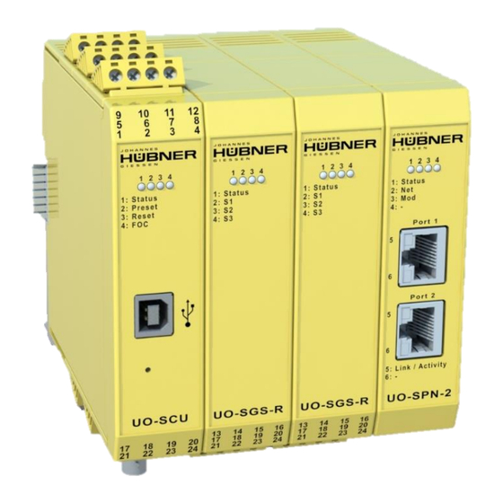
UO – function modules Assembly Manual 3 Assembly 3.1 Order The following points must be observed during installation: • The UO-SCU or UO-ECU controller module must be mounted on the left-hand side as the first module (marked red). • Communication modules (UO-EPB, UO-SPB, UO-SPN, UO-EPN, UO-EEI) are to be mounted on the right-hand side as the last modules (marked blue). -
Page 9: Mounting On The Top-Hat Rail
UO – function modules Assembly Manual 3.2 Mounting on the top-hat rail 1. Mount the bus connector on the top-hat rail. To engage, ensure that the individual bus connectors are first hooked in on one side. The opposite side is then engaged with pressure. -
Page 10: Disassembly
UO – function modules Assembly Manual 3.3 Disassembly 1. The cables on the terminal strips do not have to be disconnected individually, as the entire terminal strips can be pulled off together with the clamped cables. This facili- tates the installation of a replacement device. 2.
Need help?
Do you have a question about the U-ONE-SAFETY-LWL and is the answer not in the manual?
Questions and answers