Table of Contents
Advertisement
Quick Links
English
Operating and assembly instructions
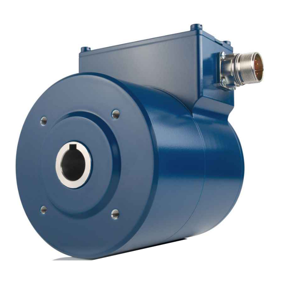
Incremental hollow shaft encoder with functional safety
FGH 41 in hollow shaft design
certified according to
and according to
Read the operating and assembly instructions prior to
assembly, starting installation and handling!
Keep for future reference!
Translation of the original operating and assembly instructions
ID 78427
EN 61508 part 1-7:2010 / IEC 62061:2015 SIL CL2 and
EN ISO 13849-1: PL d
EN 61508 Part 1-7:2010 / IEC62061:2015 SIL CL3 and
EN ISO 13849-1: PL e
Issue: 2022-09-08
Advertisement
Table of Contents

Subscribe to Our Youtube Channel
Related Manuals for Hubner FGH 41


Summary of Contents for Hubner FGH 41
- Page 1 English Operating and assembly instructions Incremental hollow shaft encoder with functional safety FGH 41 in hollow shaft design certified according to EN 61508 part 1-7:2010 / IEC 62061:2015 SIL CL2 and EN ISO 13849-1: PL d and according to EN 61508 Part 1-7:2010 / IEC62061:2015 SIL CL3 and...
- Page 2 Incremental hollow shaft encoder FGH 41 Manufacturer / Publisher Johannes Hübner Phone: +49 641 7969 0 Fabrik elektrischer Maschinen GmbH Fax: +49 641 73645 Siemensstr. 7 Internet: www.huebner-giessen.com 35394 Giessen / Germany E-mail: info@huebner-giessen.com Further current information on this product series can be found online in our Service Point.
- Page 3 Incremental hollow shaft encoder FGH 41 Trademarks ® Loctite is a registered trademark of Henkel AG & Co. KG, Düsseldorf. Brand names and product names are trademarks or registered trademarks of their respective owner. Protected trademarks bearing a ™ or ® symbol are not always depicted as such in the manual. However, the statutory rights of the respective owners remain unaffected.
-
Page 4: Table Of Contents
Technical notes ........................26 Required tools .......................... 26 Mounting preparations ......................26 Mounting of FGH 41, (hollow shaft design) ................27 Dismantling the FGH 41 ......................29 6 Installation / Preparation for Commissioning ..............30 Electrical connection Terminal box connection ................. 30 EMC requirements ........................ - Page 5 11 Maintenance ........................43 12 Accessories ........................44 Draw-off-tool ........................... 44 Mating connector ........................44 13 Dimension drawings .......................45 FGH 41 T (hollow shaft design) ....................45 FGH 41 K (hollow shaft design) ....................47 FGH 41 K (with torque bracket) ....................48 FGH41_Manual-en_R2...
-
Page 6: General Information
These operating and assembly instructions are supplemented by other documentation such as product data sheets, dimension drawings, connection diagrams, prospects, etc. The scope of delivery includes the incremental hollow shaft encoder FGH 41 and the operating and assembly instructions. The operating and assembly instructions may be requested separately. -
Page 7: General Functional Description
Verband der Elektrotechnik, Elektronik und Informationstechnik (Association for Electrical, Electronic and Information Technologies) Repeat test Repetitive test to detect hidden dangerous failures in a safety-related system. (proof test) General functional description The rotary measuring system FGH 41 is a safe and incremental position measuring system. FGH41_Manual-en_R2... - Page 8 Incremental hollow shaft encoder FGH 41 The measuring system has been designed so that it can be used in systems which require the following safety functions according to EN 61800-5-2: Safe Direction (SDI) Safe Stop 1 (SS1) Safe Stop 2 (SS2) ...
-
Page 9: Main Features
Incremental hollow shaft encoder FGH 41 1.3.1 Main Features The entire system electronics has a discrete design. Neither microcontrollers nor programmable logic elements are contained in the system electronics. There is no interpolation or signal multiplexing. All signal lines are led separately within the electronics. -
Page 10: Basic Safety Instructions
Incremental hollow shaft encoder FGH 41 2 Basic safety instructions Explanation of symbols and notes Warnings are indicated by symbols in these operating and assembly instructions. The warnings are introduced by signal words that express the scope of the hazard. -
Page 11: General Risks When Using The Product
Incremental hollow shaft encoder FGH 41 General risks when using the product The product, hereinafter referred to as the measuring system, is manufactured according to state-of-the-art technology and accepted safety rules. Nevertheless, non-intended use can pose a danger to life and limb of the user or third parties, or lead to impairment of the... -
Page 12: Non-Intended Use
Incremental hollow shaft encoder FGH 41 Non-intended use WARNING! NOTICE! Danger of death, physical injury and damage to property in case of non- intended use of the measuring system! The following areas of use are especially forbidden: – in environments where there is an explosive atmosphere –... -
Page 13: Mandatory Safety Checks / Measures
Incremental hollow shaft encoder FGH 41 2.5.1 Mandatory safety checks / measures Measures for commissioning, changes SCS error reaction Check that the desired automation task is executed as required. STOP Check by the SCS SCS error reaction Check of incremental data according to the present automation STOP task and safety function. -
Page 14: Warranty And Liability
Incremental hollow shaft encoder FGH 41 Warranty and liability In principle the "General Terms and Conditions" of Johannes Hübner - Fabrik elektrischer Maschinen GmbH apply. These are available to the operator with the Order Confirmation or when the contract is concluded at the latest. Warranty and liability claims in the case of... - Page 15 Incremental hollow shaft encoder FGH 41 The responsibility for assembly, installation, commissioning and operation must be clearly defined. The obligation exists to provide supervision for trainee personnel. FGH41_Manual-en_R2...
-
Page 16: Safety Information
Incremental hollow shaft encoder FGH 41 Safety information WARNING! NOTICE! NOTES! Destruction, damage and malfunction of the measuring system! – Only carry out wiring work or opening and closing of electrical connections with the system de-energized. – Do not undertake any welding work if the measuring system is already wired or switched on. -
Page 17: Transport, Packaging And Storage
Incremental hollow shaft encoder FGH 41 NOTES! The measuring system contains components and assemblies susceptible to electrical discharge, which can be destroyed if incorrectly handled. Touching the measuring system connection contacts with the fingers must be avoided or the relevant ESD protective measures must be applied. -
Page 18: Storage Of Packages (Devices)
Incremental hollow shaft encoder FGH 41 Storage of packages (devices) Keep dry Keep packages dry and free from dust; protect from moisture Protect against heat Protect packages from heat above 40° C and direct sunlight If you intend to store the device for a longer period of time (> 6 months) we recommend you use protective packaging (with desiccant). -
Page 19: Technical Data
Incremental hollow shaft encoder FGH 41 4 Technical Data Safety Functional safety EN 61508 Part 1-7 Safety Integrity Level (SIL) SDI, SS1, SS2, SOS, SLP, SLI, SCA SLS, SSR, SSM, SLA, SAR EN ISO 13849-1 Performance Level (PL) SDI, SS1, SS2, SOS, SLP, SLI, SCA - PLd / Kat. -
Page 20: Electrical Characteristics
Incremental hollow shaft encoder FGH 41 Electrical characteristics 4.2.1 General Supply voltage 12…30 V DC acc. to IEC 60364-4-41, SELV/PELV Reverse polarity protection Short-circuit protection Yes, by internal 1 A safety fuse Yes, up to ≤ 60 V DC Overvoltage protection... -
Page 21: Device-Specific
Incremental hollow shaft encoder FGH 41 4.2.2 Device-specific Accuracy 10 bit, 11 bit, 12 bit; depending on the device Usable resolution configuration Safety-related + 2 bit interpolated Functional + 8 bit interpolated Variant 1 Incremental analog output signals Periods / revolution 1024, 2048, 4096 acc. -
Page 22: Ambient Conditions
Incremental hollow shaft encoder FGH 41 Ambient conditions Vibration ≤ 100 m/s EN 60068-2-6 , sine 55-500 Hz Shock ≤ 1000 m/s EN 60068-2-27 , half-sine 11 ms Immunity to disturbance EN 61000-6-2 Transient emissions EN 61000-6-3 -40 °C…+85 °C Working temperature = 85 –... -
Page 23: Mechanical Characteristics Fgh 41
Incremental hollow shaft encoder FGH 41 Mechanical characteristics FGH 41 Mechanically permissible speed 3000 rpm – Degree of protection IP66 Observe derating for permissible working – Note temperature Electrically permissible speed [rpm] = (output frequency [Hz] / no. of pulses per rev.) * 60 rpm... -
Page 24: Type Code
Incremental hollow shaft encoder FGH 41 Type code FGH 41 G-90G- Incremental encoder Construction type H = hollow shaft Series Connections T = 12-pole round plug M23 K = Terminal strip in terminal box Pulses per rotation 1024, 2048, 4096... -
Page 25: Assembly
Incremental hollow shaft encoder FGH 41 5 Assembly Safety instructions WARNING! At assembly, dismantling and other work to the device the basic safety instructions to chapter 2 must be observed. The assembly, dismantling and other work of the measuring system must only... -
Page 26: Technical Notes
22) only with screwed-on mating connectors or blind plugs! Deep groove ball bearings Incremental hollow shaft encoders FGH 41 are fitted with maintenance-free, greased "for-life" deep groove bearings. Bearings must be changed by the manufacturer only. Opening the encoder renders the guarantee null and void. -
Page 27: Mounting Of Fgh 41, (Hollow Shaft Design)
Incremental hollow shaft encoder FGH 41 Mounting of FGH 41, (hollow shaft design) Fig. 1: FGH 41 (mounting example) 1. Mount the adapter shaft (1) and align using a dial gauge. NOTES! The maximum radial run-out of the adapter shaft is 0.05 mm. - Page 28 Incremental hollow shaft encoder FGH 41 4. Secure the hollow-shaft device with the aid of the supplied hexagon socket head cap screw (5) (property class: 8.8)! NOTES! The hexagon head socket cap screws(5) are coated with a microencapsulated adhesive as locking agent.
-
Page 29: Dismantling The Fgh 41
Incremental hollow shaft encoder FGH 41 Dismantling the FGH 41 WARNING! At assembly, dismantling and other work to the device the basic safety instructions to chapter 2 must be observed. The assembly, dismantling and other work on the device may only be carried out by qualified personnel. -
Page 30: Installation / Preparation For Commissioning
Incremental hollow shaft encoder FGH 41 6 Installation / Preparation for Commissioning Electrical connection Terminal box connection 1. Open the terminal box cover (10) (see Fig. 1). CAUTION! Do not allow moisture to enter the terminal box when the cover is open! 2. -
Page 31: Emc Requirements
Incremental hollow shaft encoder FGH 41 EMC requirements WARNING! Deactivation of the safety function due to radiated or conducted interference sources! – Radiated interference sources due to radiophones, lightning strikes in networks, mobile phones and emissions from individual devices can cause malfunctions in the measuring system. -
Page 32: Emc Conform Wiring Schemes
Incremental hollow shaft encoder FGH 41 EMC conform wiring schemes 6.3.1 Connection scheme 1 FG 41 1x Ground connection (connection possibilities Avoid ground loops Connect all shields double-sided Shielding must not be interrupted Twisted pair wires (A,/A), (B,/ B) 6.3.2 Connection scheme 2... -
Page 33: Connection Scheme 3
Incremental hollow shaft encoder FGH 41 6.3.3 Connection scheme 3 FG 41 1x Ground connection (connection possibilities Avoid ground loops Connect all shields double-sided Shielding must not be interrupted Twisted pair wires (A,/A), (B,/ B) FGH41_Manual-en_R2... -
Page 34: Ground Connection - Measuring System
Incremental hollow shaft encoder FGH 41 Ground connection – measuring system In principle, it is recommended that the ground connection of the measuring system has a good conductive connection to the functional earth of the machine. (Cable with min. 4 mm²). An earthing terminal is provided on the measuring system for this purpose see dimension drawing HM 18 M 113294a. -
Page 35: Permitted Cable Length
Incremental hollow shaft encoder FGH 41 Permitted cable length The permissible cable length at the transmission of incremental signals depends on the output frequency, the applied supply voltage and the ambient temperature of the measuring system, see the following diagrams. -
Page 36: Square Wave Incremental-Signals (Ttl/Htl)
Incremental hollow shaft encoder FGH 41 6.6.2 Square wave incremental-signals (TTL/HTL) TTL-Interface: Output frequency in kHz Fig. 2: Maximum permissible cable length for TTL interface HTL-Interface: Output frequency in kHz Fig. 3: Maximum permissible cable length for HTL interface FGH41_Manual-en_R2... -
Page 37: Connection Instructions For Plug Connection
Incremental hollow shaft encoder FGH 41 Connection instructions for plug connection The electrical equipment features are mainly determined by the variable connection technology. NOTES! The connection can only be made in conjunction with the device-specific pin assignment! When the measuring system is delivered, a printed version of the pin assignment is enclosed and can also be downloaded later. -
Page 38: Variant 1, Analog Incremental Signals (Sin/Cos)
Incremental hollow shaft encoder FGH 41 Variant 1, analog incremental signals (SIN/COS) The number of periods / revolution is dependent on the device variant. Resolutions of 1024, 2048 and 4096 periods / revolution are supported. Measuring the signals against 0 V gives the following signal curve: Fig. -
Page 39: Variant 2, Square - Wave Incremental Signals (Ttl/Htl)
Incremental hollow shaft encoder FGH 41 Variant 2, square - wave incremental signals (TTL/HTL) The number of pulses / revolution is dependent on the device variant. Resolutions of 1024, 2048 and 4096 pulses / revolution are supported. The output levels are also specified by the factory setting; TTL output stages and HTL output stages are supported. -
Page 40: Connection Diagram
Incremental hollow shaft encoder FGH 41 8 Connection diagram 12-pole round plug FGH 41T Connection diagram PN 228-400a FGH 41K Connection diagram PN 228-410 Terminal box FGH41_Manual-en_R2... -
Page 41: Replacing The Measuring System
Incremental hollow shaft encoder FGH 41 9 Replacing the Measuring System The following points must be noted when replacing the measuring system: ● The new measuring system must have the same article number (ID) as the measuring system being replaced; any deviations must be expressly clarified with Johannes Hübner Giessen. -
Page 42: Checklist
Incremental hollow shaft encoder FGH 41 10 Checklist We recommend that you print out and work through the checklist for commissioning, when replacing the measuring system and when changing the parameterization of a previously accepted system, sign it and store it as part of the overall system documentation. -
Page 43: Maintenance
Incremental hollow shaft encoder FGH 41 11 Maintenance WARNING! At inspection of the measuring system and the mounting, the basic safety instructions contained in chapter 2 must be observed. The inspection of the measuring system and the mounting must only be carried out by qualified personnel! The device is maintenance-free. -
Page 44: Accessories
The accessories/spare parts listed below can be ordered from the service address on page 2 if required Draw-off-tool Draw-off-tool Order-Nr.: ID 23029 for hollow shaft encoder FGH 41 (not included in the scope of delivery) Mating connector Mating connector: BG-109647 FGH41_Manual-en_R2... -
Page 45: Dimension Drawings
Incremental hollow shaft encoder FGH 41 13 Dimension drawings 41 T (hollow shaft de- sign) FGH41_Manual-en_R2... - Page 46 Incremental hollow shaft encoder FGH 41 FGH 41 T 12-pole round plug M23 HM 18 M 113294a FGH41_Manual-en_R2...
-
Page 47: Fgh 41 K (Hollow Shaft Design)
Incremental hollow shaft encoder FGH 41 FGH 41 K (hollow shaft design) FGH 41 K Terminal box HM 19 M 114466 FGH41_Manual-en_R2... -
Page 48: Fgh 41 K (With Torque Bracket)
Incremental hollow shaft encoder FGH 41 FGH 41 K (with torque bracket) FGH 41 K FGH41 with torque bracket HM 20 M 114993 FGH41_Manual-en_R2...
Need help?
Do you have a question about the FGH 41 and is the answer not in the manual?
Questions and answers