Table of Contents
Advertisement
Quick Links
English
Operating and Assembly Instructions
®
U-ONE
-SAFETY-Compact USC 42
Universal Encoder System
Read the operating and assembly instructions prior to
assembly, starting installation and handling!
Keep for future reference!
Translation of the original Operating and Assembly Instructions
Issued October. 2018
ID 74445
Advertisement
Table of Contents

Related Manuals for Hubner U-ONE-SAFETY-Compact USC 42


Summary of Contents for Hubner U-ONE-SAFETY-Compact USC 42
- Page 1 English Operating and Assembly Instructions ® U-ONE -SAFETY-Compact USC 42 Universal Encoder System Read the operating and assembly instructions prior to assembly, starting installation and handling! Keep for future reference! Translation of the original Operating and Assembly Instructions Issued October. 2018 ID 74445...
- Page 2 Johannes Hubner Fabrik elektrischer Maschinen GmbH. Subject to errors and changes due to technical improvements. Copyright © Johannes Hubner Fabrik elektrischer Maschinen GmbH. All rights reserved. USC42_Manual-en_R7...
-
Page 3: Table Of Contents
® U-ONE -SAFETY-Compact USC 42 Operating and Assembly Instructions Table of contents General .......................... 5 Information about the Operating and Assembly Instructions ........... 5 Scope of delivery ........................5 Explanation of symbols ......................5 Warranty and liability ........................ 6 Organizational measures ......................6 Copyright .......................... - Page 4 ® U-ONE -SAFETY-Compact USC 42 Operating and Assembly Instructions Error switch ..........................29 Safe PROFIBUS module (SPB C) ..................29 6.5.1 Electrical data PROFIBUS ....................30 6.5.2 Bus addressing ....................... 31 6.5.3 PROFIBUS transfer technology, cable specification ............31 6.5.4 Bus termination ......................
-
Page 5: General
® U-ONE -SAFETY-Compact USC 42 Operating and Assembly Instructions 1 General 1.1 Information about the Operating and Assembly Instructions These operating and assembly instructions provide important instructions for working ® with the U-ONE -SAFETY-Compact. They must be carefully read prior to starting all ®... -
Page 6: Warranty And Liability
Operating and Assembly Instructions 1.4 Warranty and liability In principle the "General Terms and Conditions" of Johannes Hubner Fabrik elektrischer Maschinen GmbH apply. These are available to the operator with the Order Confirmation or when the contract is concluded at the latest. Warranty and... -
Page 7: Guarantee Terms
® U-ONE -SAFETY-Compact USC 42 Operating and Assembly Instructions 1.7 Guarantee terms The guarantee terms are provided in the manufacturer´s terms and conditions. 1.8 Customer service For technical information personnel is available that can be reached per telephone, fax or email. See manufacturer´s address on page 2. 2 Basic safety instructions DANGER! This section provides an overview of all the important safety aspects that ensure... -
Page 8: Intended Use
® U-ONE -SAFETY-Compact USC 42 Operating and Assembly Instructions 2.3 Intended use Depending on the device configuration, the USC 42 can be used to, to detect angular movements (SPB/SPN) for safe, position-dependent switching of floating relay contacts (SRC C-R) ... -
Page 9: Safety Information
The type plate specifies the technical characteristics of the USC 42. If the type plate is no longer legible or if the type plate is completely missing, the USC 42 must not be operated. Contact Hubner Service (see page 2). NOTES! -
Page 10: Assembly
® U-ONE -SAFETY-Compact USC 42 Operating and Assembly Instructions 3 Assembly 3.1 Safety instructions WARNING! At assembly, dismantling and other work to the device the basic safety instructions to chapter 2 must be observed. The assembly and the dismantling of the measuring system must only be carried out by qualified personnel. -
Page 11: Technical Notes
® U-ONE -SAFETY-Compact USC 42 Operating and Assembly Instructions 3.2 Technical notes NOTES! Do not use a hammer or similar tool during installing, disassembly or other work on the USC 42 due to the risk of damage occurring to the bearings or coupling. Housing surface temperature The housing surface temperature must be within the permissible range (see chapter 5.3). - Page 12 ® U-ONE -SAFETY-Compact USC 42 Operating and Assembly Instructions Fastening screws To ensure the encoder is reliably mounted the following conditions must be satisfied: Construction type B5 flange mounting B3 foot mounting Screws ISO4017 M6 ISO4017 M8 Washers ISO7089 A6 DIN6340 A8 Number of screws Min.
-
Page 13: Mounting B5 Type (Flange)
® U-ONE -SAFETY-Compact USC 42 Operating and Assembly Instructions 3.3 Mounting B5 type (flange) NOTES! For a mounting example please refer to dimension drawing (chapter 11). The installation described below is offered as an example only and may vary according to the coupling and flange type. It is essential to observe the specific instructions provided by the manufacturer of the coupling. -
Page 14: Mounting Of Construction Type B35 (Flange And Foot)
® U-ONE -SAFETY-Compact USC 42 Operating and Assembly Instructions 4. Fasten the intermediate disc (10) on the drive side by using of the fastening screws and washers (2). 5. Fasten the intermediate flange (4) to the intermediate disc (10) by using the fastening screws(14) and washers (14). -
Page 15: Dismantling
® U-ONE -SAFETY-Compact USC 42 Operating and Assembly Instructions 1. Grease the drive shaft lightly (1). 2. Secure the coupling hub on the drive shaft (1) with a grub screw or cheese head screw (3) (depending on the coupling type). 3. -
Page 16: Installation
® U-ONE -SAFETY-Compact USC 42 Operating and Assembly Instructions If the project does not support a neighbourhood detection, in case of a device replacement it must be ensured that the device name assigned before also is assigned to the new USC 42. When the system boots up the device name is detected again and the new MAC-Address and IP-Address is assigned to the device name automatically (only PROFINET). -
Page 17: Electrical Connection
® U-ONE -SAFETY-Compact USC 42 Operating and Assembly Instructions 4.2 Electrical connection 1. Open the terminal box cover (9) (Fig. 3-2). CAUTION! Do not allow moisture to enter the terminal box when the terminal cover is open. 2. Remove the cap of the cable gland (10) (Fig. 3-2). 3. -
Page 18: Technical Data
® U-ONE -SAFETY-Compact USC 42 Operating and Assembly Instructions 5 Technical Data 5.1 Type plate The figure below shows an example of a type plate. The type plate is located on the side of the housing and contains the following information: ... -
Page 19: Mechanical Data
® U-ONE -SAFETY-Compact USC 42 Operating and Assembly Instructions 5.3 Mechanical data Specification Value 100 N axial, 120 N radial Max. encoder shaft load Shaft end Ø 14j6 x 30 mm Mech. permissible speed max. 2800 rpm -25°C … + 70° C Temperature range (DIN EN 60068-2-6 (8,7 …... -
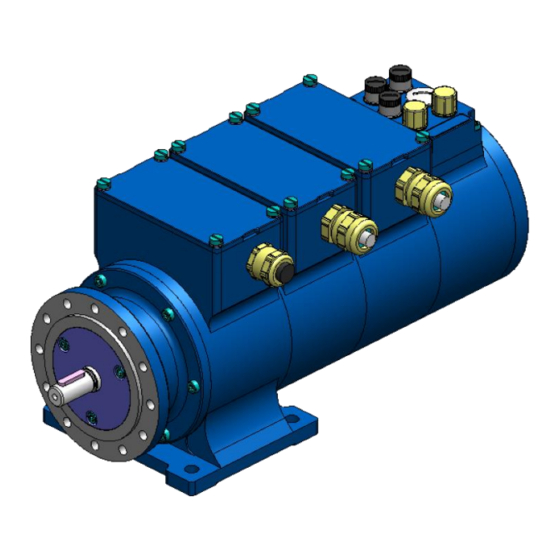
Page 20: Design And Function
® U-ONE -SAFETY-Compact USC 42 Operating and Assembly Instructions 6 Design and function The USC 42 consists of a basic unit as well as maximum 4 housing modules in which it is possible to integrate a maximum of 6 function modules. Fig. -
Page 21: Basic Unit (Scu C)
® U-ONE -SAFETY-Compact USC 42 Operating and Assembly Instructions 6.1 Basic unit (SCU C) The SCU C module is the central control module of the USC 42. The following options are available: 1. SCU C-I current output (included with the standard version) 2. -
Page 22: Operating Statuses And Indicators
® U-ONE -SAFETY-Compact USC 42 Operating and Assembly Instructions 6.1.2 Operating statuses and indicators Position / Terminal box SCU C Output Output Error Operating speed status error switch module status Status LED Failure LED switch (HTL) (HTL) (optional) (optional) (green) (red) (optional) Flashing... -
Page 23: Error- And Status Output
® U-ONE -SAFETY-Compact USC 42 Operating and Assembly Instructions 6.1.3 Error- and status output The basic unit of the USC 42 is equipped with an error and a status output. Both outputs are 2 channel (Cat. 3) types. Error output An error is indicated by a low-level signal at the error output, which can only be reset via the configuration software "US42Pro"... -
Page 24: Reset Input
® U-ONE -SAFETY-Compact USC 42 Operating and Assembly Instructions 6.1.4 Reset input A reset leads to the entire USC 42 being re-initialized. The reset input is a 2 channel (Cat. 3) type. When quiescent both inputs must be high. A reset is Reset1/2 initiated if both input signals are low. -
Page 25: Incremental Output (Non Safety-Related)
® U-ONE -SAFETY-Compact USC 42 Operating and Assembly Instructions 6.1.6 Incremental output (non safety-related) The optional incremental output supplies 1024 or 4096 pulses / rotation. The output signals opposite are available (factory setting: 1024). Fig. 6-6: Incremental signals 6.1.6.1 Electrical data incremental output Value Pulse rates 4096 / 1024 (configurable) - Page 26 ® U-ONE -SAFETY-Compact USC 42 Operating and Assembly Instructions Electrical data current output speed: Specification Value Max. speed 2800 rpm Accuracy 0,5% FSR Update rate approx. 2 ms Max. load 400 at supply voltage < 16V 600 at supply voltage ≥ 16V resistance Connection diagram PN164-401b (see Chap.11.2)
-
Page 27: Safety Position Switch Module With Safety Relays(Src C-R)
® U-ONE -SAFETY-Compact USC 42 Operating and Assembly Instructions 6.2 Safety Position switch module with safety relays(SRC C-R) The position switch open or close depending on the position value. The user is able to configure a cam with a switch, in other words, a switch-on and switch-off position (red line) and the associated hysteresis switching points (blue line). -
Page 28: Safe Speed Switch Module With Safety Relay (Sgs C-R)
® U-ONE -SAFETY-Compact USC 42 Operating and Assembly Instructions 6.3 Safe Speed switch module with safety relay (SGS C-R) The speed switches open and close depending on the speed value. With a speed switch the user is able to configure overspeed cut-off and/or underspeed cut-off and the associated hysteresis switching points (dotted line). -
Page 29: Switching Accuracy
® U-ONE -SAFETY-Compact USC 42 Operating and Assembly Instructions 6.3.2 Switching accuracy The switching accuracy (max. switching errors) Δn is made up of: : ≤10 ms Switching time T Measuring accuracy ΔF (Error in the determination of speed): ≤ 2 % Δ... -
Page 30: Electrical Data Profibus
® U-ONE -SAFETY-Compact USC 42 Operating and Assembly Instructions 6.5.1 Electrical data PROFIBUS Detail Value Supply voltage is supplied by SCU C Additional module power max. 1,5 W consumption SPB 28 Bit Total resolution 13 Bit (8192 steps/revolution) Singel-turn ... -
Page 31: Bus Addressing
® U-ONE -SAFETY-Compact USC 42 Operating and Assembly Instructions Bus addressing 6.5.2 WARNING! CAUTION! Destruction, damage and malfunction of the USC 42 in case of infiltration of foreign substances and damp. The access to the address switches has to be locked after the settings with the screw plug. -
Page 32: Bus Termination
If the USC 42PROFIBUS module is the last station in the PROFIBUS- segment, the bus must be terminated via flange socket Xn.3 in accordance with the PROFIBUS standard. The bus termination can also be obtained from Johannes Hubner Giessen (see chapter 10). USC42_Manual-en_R7... -
Page 33: Saftey Profinet Module (Spn C)
® U-ONE -SAFETY-Compact USC 42 Operating and Assembly Instructions 6.6 Saftey PROFINET module (SPN C) The PROFINET module includes: PROFINET IO interface with PROFIsafe protocol, for transfer of a safe position and speed Quick process data channel via PROFINET IO, not safety-oriented The "safe data"... -
Page 34: Profisafe Destination Address "F_Dest_Add
® U-ONE -SAFETY-Compact USC 42 Operating and Assembly Instructions Detail Value Transmission CAT-5 cable, shielded (STP), ISO/IEC 11801 Addressing by name (name allocation about engineering tool). (parameterizable via Assignment nameMAC during system boot PROFINET IO) Electrical connection M12 connector Connection diagram PN164-412a (see chapter.11.2) 6.6.2 PROFIsafe destination address “F_Dest_Add”... -
Page 35: Functional Safety
® U-ONE -SAFETY-Compact USC 42 Operating and Assembly Instructions subscribers may amount max. 100 m. This transmission link has been defined as PROFINET end-to-end link. Within an end-to-end link the number of detachable links is limited up to six connector pairs (male connector/female connector). If more than six connector pairs are required, make sure that the attenuation values for the entire link are observed (channel class-D values). -
Page 36: Device Data
® U-ONE -SAFETY-Compact USC 42 Operating and Assembly Instructions 7.3 Device data 7.3.1 Timing Power-on time T After the supply voltage is turned on initial internal diagnostic checks are carried out before the device is ready for operations. The power-on time is approx. 6 s. Switching time T The switching time T = max. -
Page 37: Information About Functional Safety
® U-ONE -SAFETY-Compact USC 42 Operating and Assembly Instructions 7.4 Information about functional safety CAUTION! The power supply unit used must not exceed a voltage of 36 VDC even during a fault condition or corresponding voltage limiting measures must be employed, for example installing a surge suppressor. -
Page 38: Inspections
® U-ONE -SAFETY-Compact USC 42 Operating and Assembly Instructions 8 Inspections 8.1 Safety instructions WARNING/PERSONNEL! Skilled technical staff only are permitted to inspect the USC 42 and its installation. Observe the safety instructions contained in chapter 2 when inspecting or working on the USC 42! 8.2 Maintenance information The device is maintenance-free. -
Page 39: Fault Table
Moisture in the terminal box Cable gland/blanking plug not Tighten cable gland/blanking tightened plug Unsuitable cable for cable Use suitable cable and cable gland glands Contact Hubner-Service (page 2) if none of the remedies listed above provides a solution! USC42_Manual-en_R7... -
Page 40: Checklist
® U-ONE -SAFETY-Compact USC 42 Operating and Assembly Instructions 8.5 Checklist We recommend that you print out and work through the checklist for commissioning, replacing the measuring system and when changing the parameterization of a previously accepted system and store it as part of the overall system documentation. Documentation reason Date Edited... -
Page 41: Transport, Packaging And Storage
® U-ONE -SAFETY-Compact USC 42 Operating and Assembly Instructions 9 Transport, packaging and storage 9.1 Safety information concerning transport CAUTION! Material damage caused by improper transport! Observe the symbols and information on the packaging: Do not throw - risk of breakage Keep dry Do not expose to heat above 40 °C or direct sunlight. -
Page 42: Accessories
® U-ONE -SAFETY-Compact USC 42 Operating and Assembly Instructions 10 Accessories The scope of supply of the USC 42 includes: The Operating and Assembly Instructions, configuration instructions, the Software & Support CD and the USB programming cable, which can also be requested separately. -
Page 43: Coupling
® U-ONE -SAFETY-Compact USC 42 Operating and Assembly Instructions 10.2 Coupling We recommend our zero-backlash, torsion-resistant coupling HKS5 with fault exclusion to attach the USC 42. The coupling meets the following requirements Description Value shock resistance 100 g (DIN EN 60068-2-27 (6 ms) (DIN EN 60068-2-6 (8,7 …... -
Page 44: Documents
® U-ONE -SAFETY-Compact USC 42 Operating and Assembly Instructions 11 Documents 11.1 Dimension drawing HM 15 M 109663 Fig. 11-1 – front view Fig. 11-2 – side view USC42_Manual-en_R7... -
Page 45: Connection Diagrams
® U-ONE -SAFETY-Compact USC 42 Operating and Assembly Instructions 11.2 Connection Diagrams NOTES! The connection diagrams are depicted on the respective terminal box cover. The shield of the signal cable is connected directly to the housing via the EMC cable gland. Connection diagram SCU C- Connection diagram SCU C-I PN164-401c... - Page 46 ® U-ONE -SAFETY-Compact USC 42 Operating and Assembly Instructions Connection diagram PROFIBUS PN164-410a Connection diagram PROFINET PN164-412a USC42_Manual-en_R7...
-
Page 47: Application Examples
® U-ONE -SAFETY-Compact USC 42 Operating and Assembly Instructions 12 Application examples The USC 42 makes available safe position / speed switches and position values via a bus module. The switches are depicted with no voltage applied. Not safety-related data lines and switches are depicted in black. 12.1 Application with safety-SPS The graphic opposite depicts the USC 42 as Safety-related SPS... - Page 48 ® U-ONE -SAFETY-Compact USC 42 Operating and Assembly Instructions USC42_Manual-en_R7...
Need help?
Do you have a question about the U-ONE-SAFETY-Compact USC 42 and is the answer not in the manual?
Questions and answers